XY-Axis Motorized Linear Stages
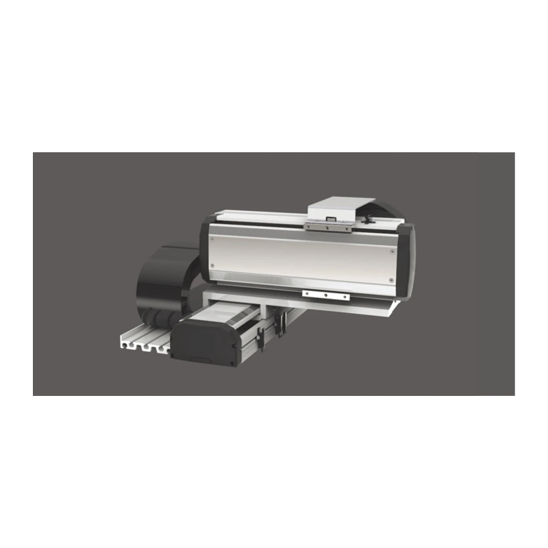
XYS650-A Series 2-axis
Screw-driven. This illustration is for reference only; see the dimensional drawing for delivery specifications. Synchronous motion accuracy is not guaranteed for standard connected stages.
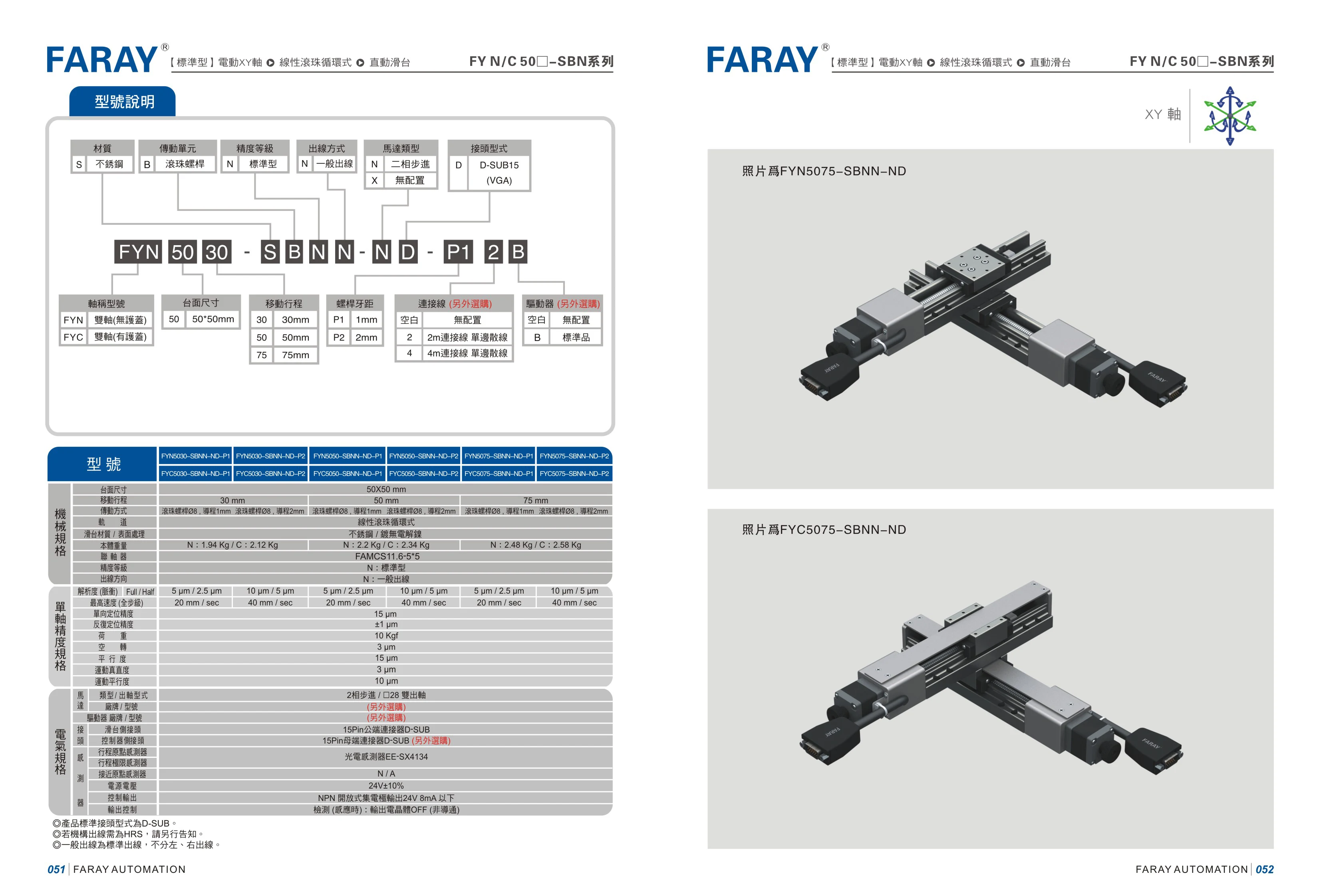
FYN/FYC Series Motorized XY Stages
The FYN/FYC series consists of standard motorized XY stages with recirculating linear ball bearings. Made of stainless steel and driven by ball screws, they are suitable for precision two-axis positioning and reciprocating motion in automated equipment. The model code specifies the material, drive unit, accuracy grade, wiring configuration, motor type, and connector type. The examples on this page have a size code of 5075, standard accuracy, standard wiring, a choice of a two-phase stepper motor or no motor, and a D-SUB15 (VGA) connector. FYN and FYC denote different configurations and can be selected according to equipment space and drive requirements.
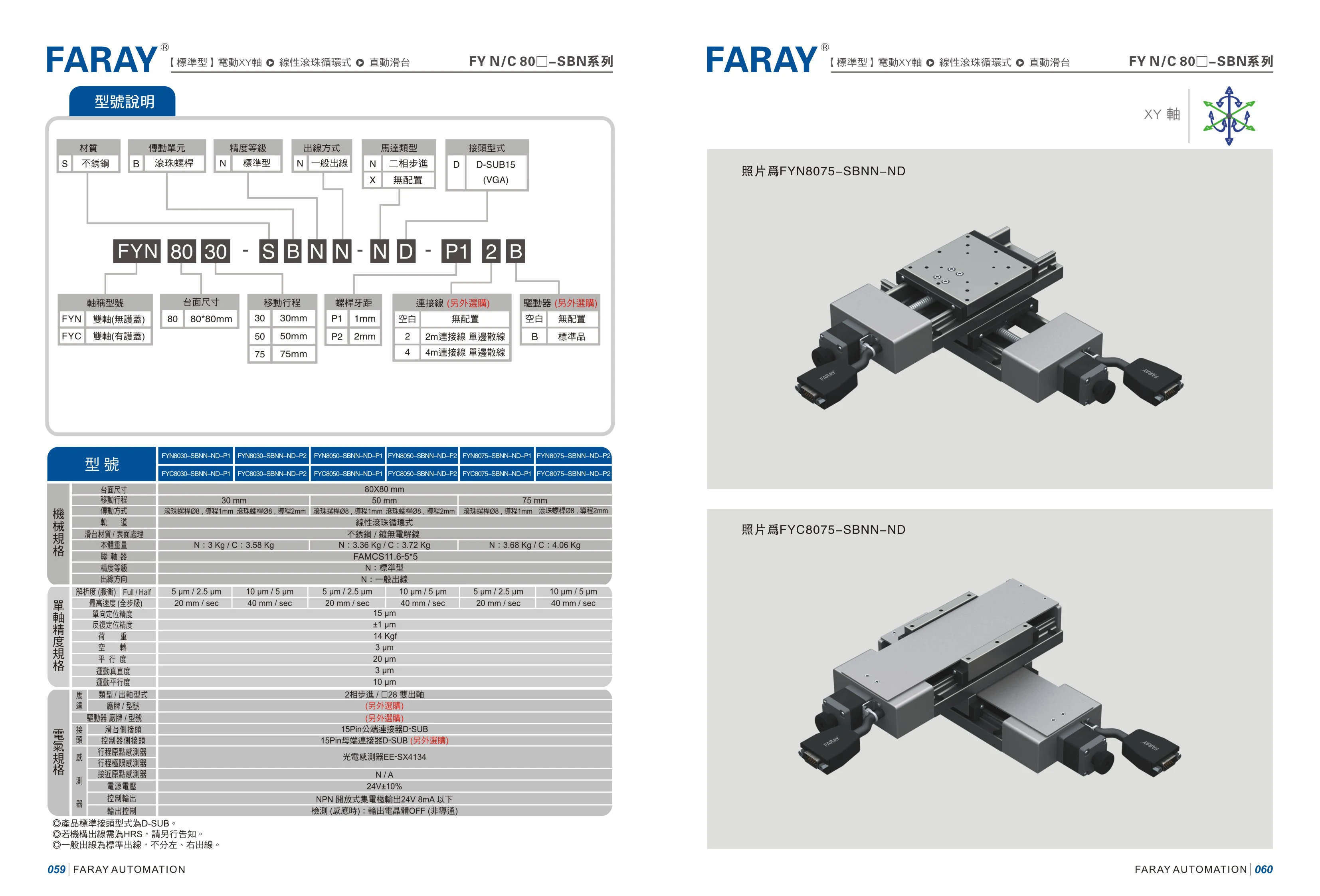
FY N/C 80□-SBN Series Motorized XY-Axis Linear Stage with Recirculating Ball Bearings
The FARAY FY N/C 80□-SBN series is a standard motorized XY-axis linear stage with recirculating ball bearings. It features an 80-size body and an 08 ball screw drive, with a choice of 1mm or 2mm lead. The stage uses linear recirculating ball guides and is made of stainless steel with an electrolytic nickel-plated finish. Standard travel is 30/50/75mm, with resolution of 5/2.5μm (1mm lead) or 10/5μm (2mm lead), maximum speed of 20/40mm/sec, unidirectional positioning accuracy of 15μm, and repeat positioning accuracy of ±1μm. The standard N-type body weighs approximately 3.0~3.68kg, while the C-type weighs approximately 3.58~4.06kg. It is suitable for automated equipment requiring precision linear positioning on two XY axes.
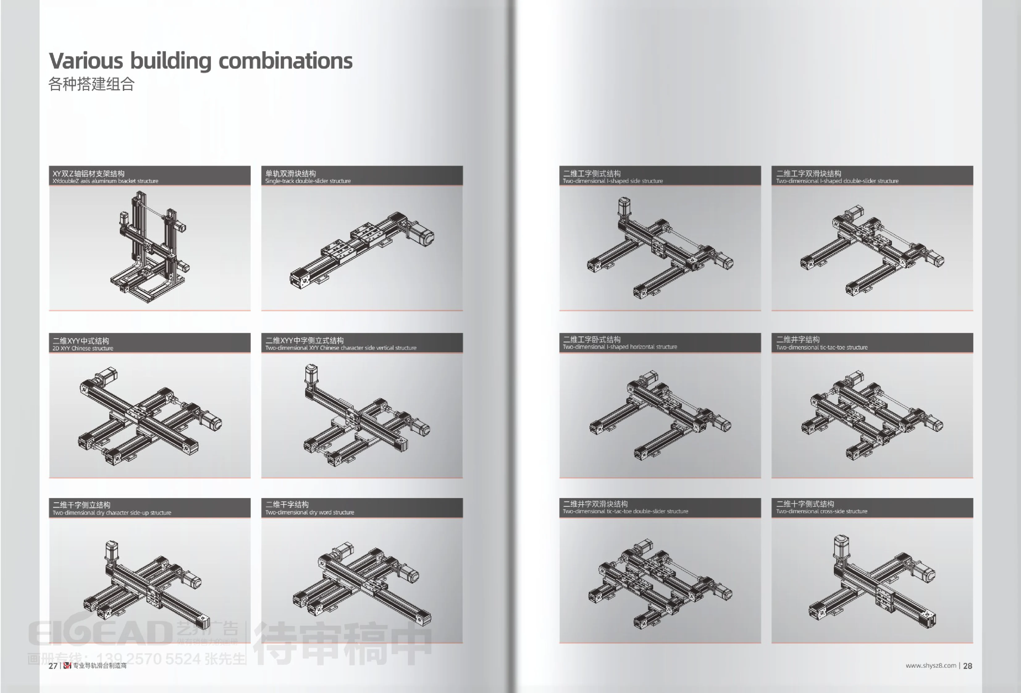
XY Multi-Axis Linear Stage Assemblies
XY multi-axis linear stage assemblies combine two or more linear stages in different spatial orientations to create a motion platform capable of two-dimensional movement along the X and Y axes, or three-dimensional movement with the addition of a Z axis. This series is categorized by configuration rather than by individual model. Options include an XY dual-Z-axis assembly with an aluminum support frame, a single-rail dual-carriage assembly, two-dimensional XY 中-shaped and side-mounted 中-shaped assemblies, two-dimensional 千-shaped and side-mounted 千-shaped assemblies, side-mounted, dual-carriage and horizontal 工-shaped assemblies, and two-dimensional 井-shaped and dual-carriage 井-shaped assemblies. Depending on travel, load direction, installation space and accuracy requirements, users can select a single-rail dual-carriage configuration for greater resistance to overturning, or a symmetrical 工-shaped or 井-shaped configuration to distribute off-center loads. These assemblies are commonly used for handling, positioning, dispensing and screw fastening in custom automation equipment. They can be paired with stepper motors, servo motors and various controllers, with cross-sectional dimensions and travel customized to the application.
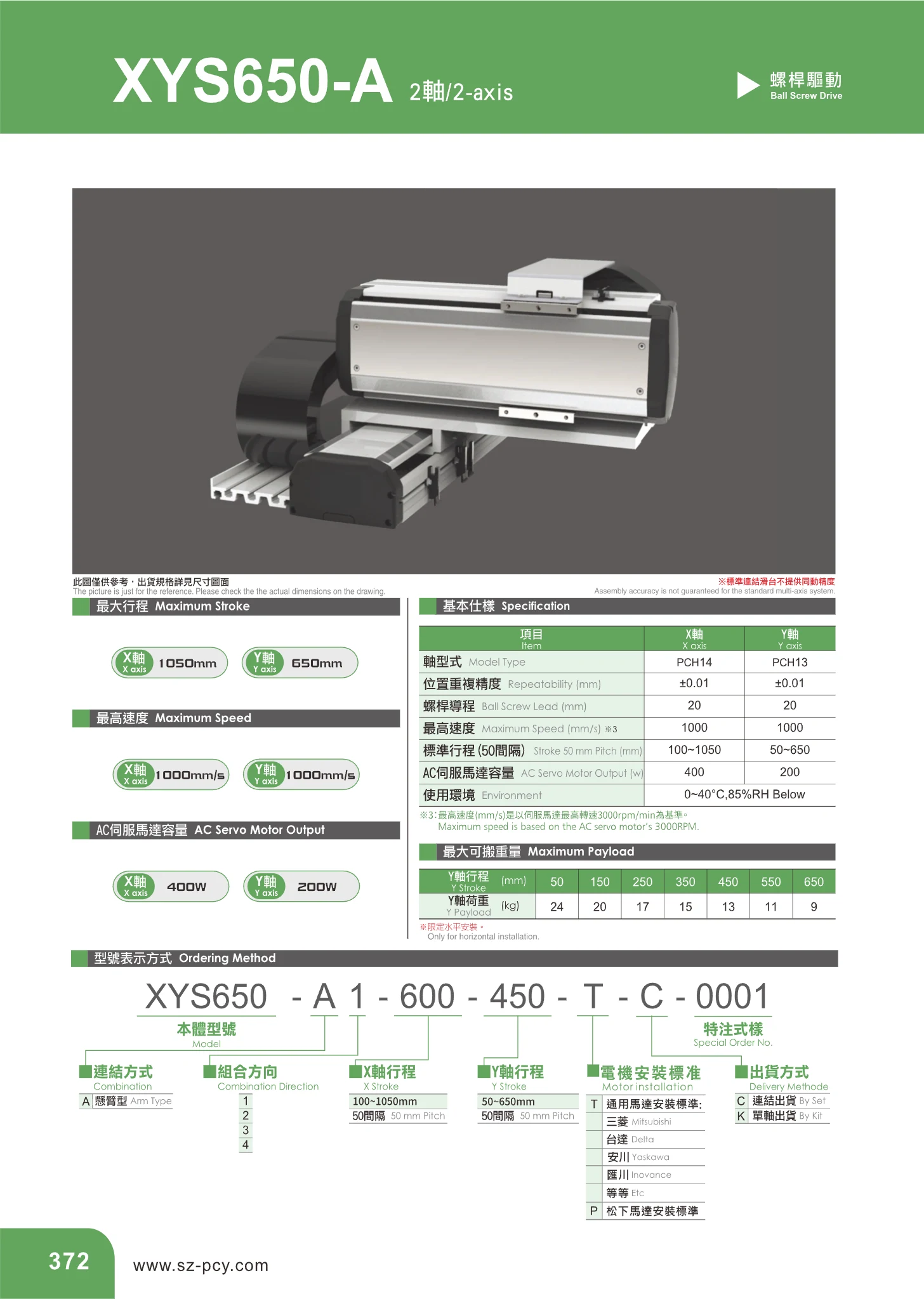
PCH Series Two-Axis Linear Modules
The PCH series consists of two-axis (X-Y) linear modules with a cross-slide structure, combining an X axis and a Y axis. Driven by ball screws and AC servo motors, they are suitable for two-dimensional positioning, material handling, dispensing, and inspection in automated equipment. The X-axis model is PCH14 and the Y-axis model is PCH13. Both axes have a positioning repeatability of ±0.01 mm, a ball screw lead of 20 mm, and a maximum speed of 1000 mm/s. Stroke lengths are available in 50 mm increments: the standard stroke range is 100~1050 mm for the X axis (PCH14) and 50~650 mm for the Y axis (PCH13). The corresponding AC servo motor ratings are 400 W for the X axis and 200 W for the Y axis. Operating conditions are 0~40 °C and below 85%RH. Users can select strokes in 50 mm increments within each axis's range and freely combine X and Y axes to create two-axis modules in different configurations.
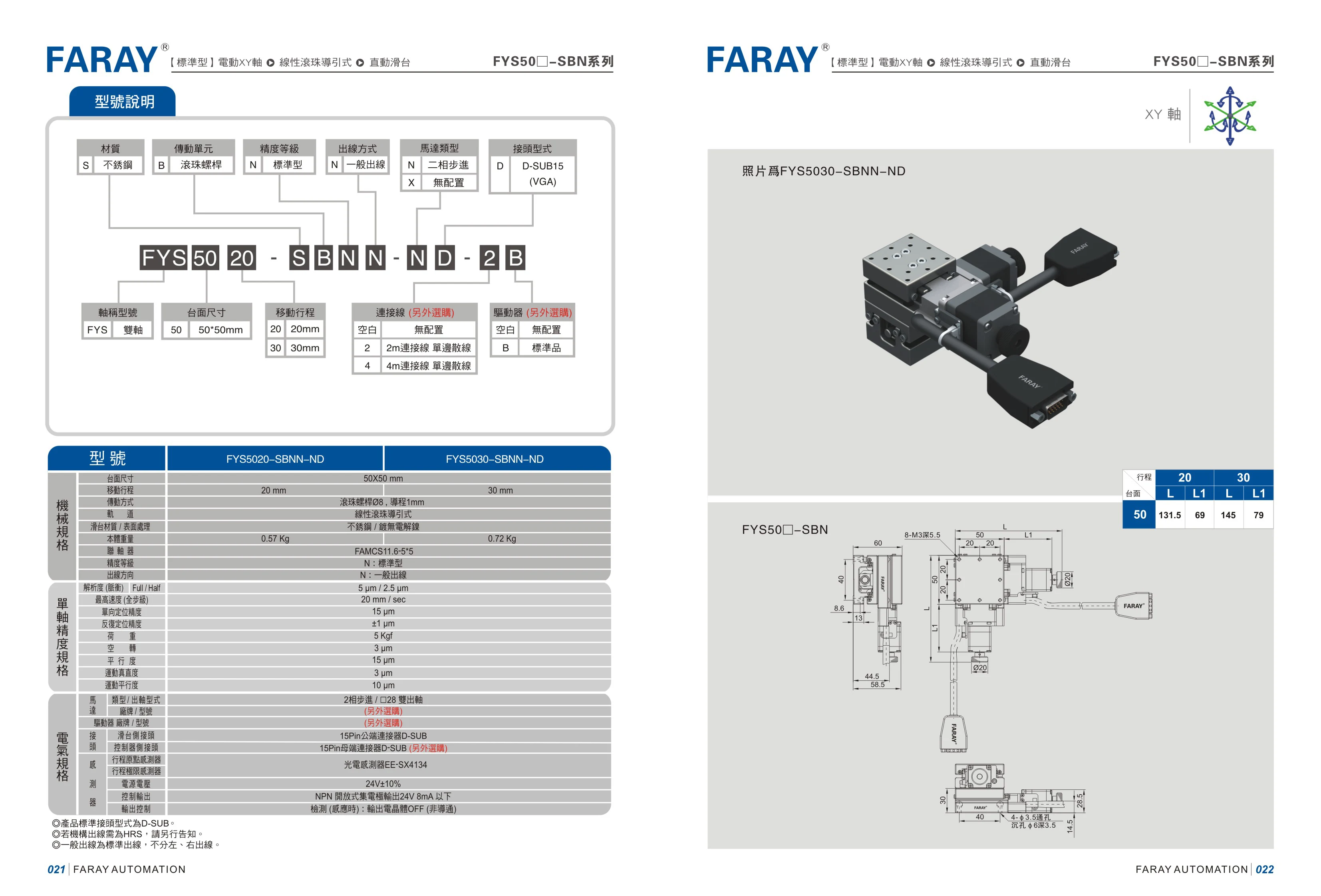
FYS50□-SBN Series Motorized XY Linear Stages with Linear Ball Guides
The FYS50□-SBN series consists of standard motorized XY linear stages with linear ball guides. Made of stainless steel, they feature ball screw drives, two-phase stepper motors, standard wiring, and D-SUB15 (VGA) connectors. The catalog lists two models, FYS5020-SBNN-ND and FYS5030-SBNN-ND, for automated systems requiring two-axis XY positioning. Some electrical and accuracy specifications on the page were duplicated or corrupted by OCR and have been excluded from the structured specifications.

XYS430-A Two-Axis Linear Module
The XYS430-A is a two-axis (XY) linear module driven by a ball screw. It uses a PCH12 axis for the X-axis and a PCH10 axis for the Y-axis. Its compact design is suitable for precision positioning in a plane. It offers a repeatability of ±0.01 mm, a ball screw lead of 20 mm and a maximum speed of 1000 mm/s, and is equipped with a 100 W AC servo motor. Standard travel ranges from 100~1050 mm for the X-axis and 50~550 mm for the Y-axis, both in 50 mm increments. The operating environment is 0~40°C and below 85%RH. It can be paired with a servo drive for multipoint positioning and is widely used for XY planar positioning in handling, dispensing, assembly and inspection applications in the electronics, semiconductor and automotive parts industries.
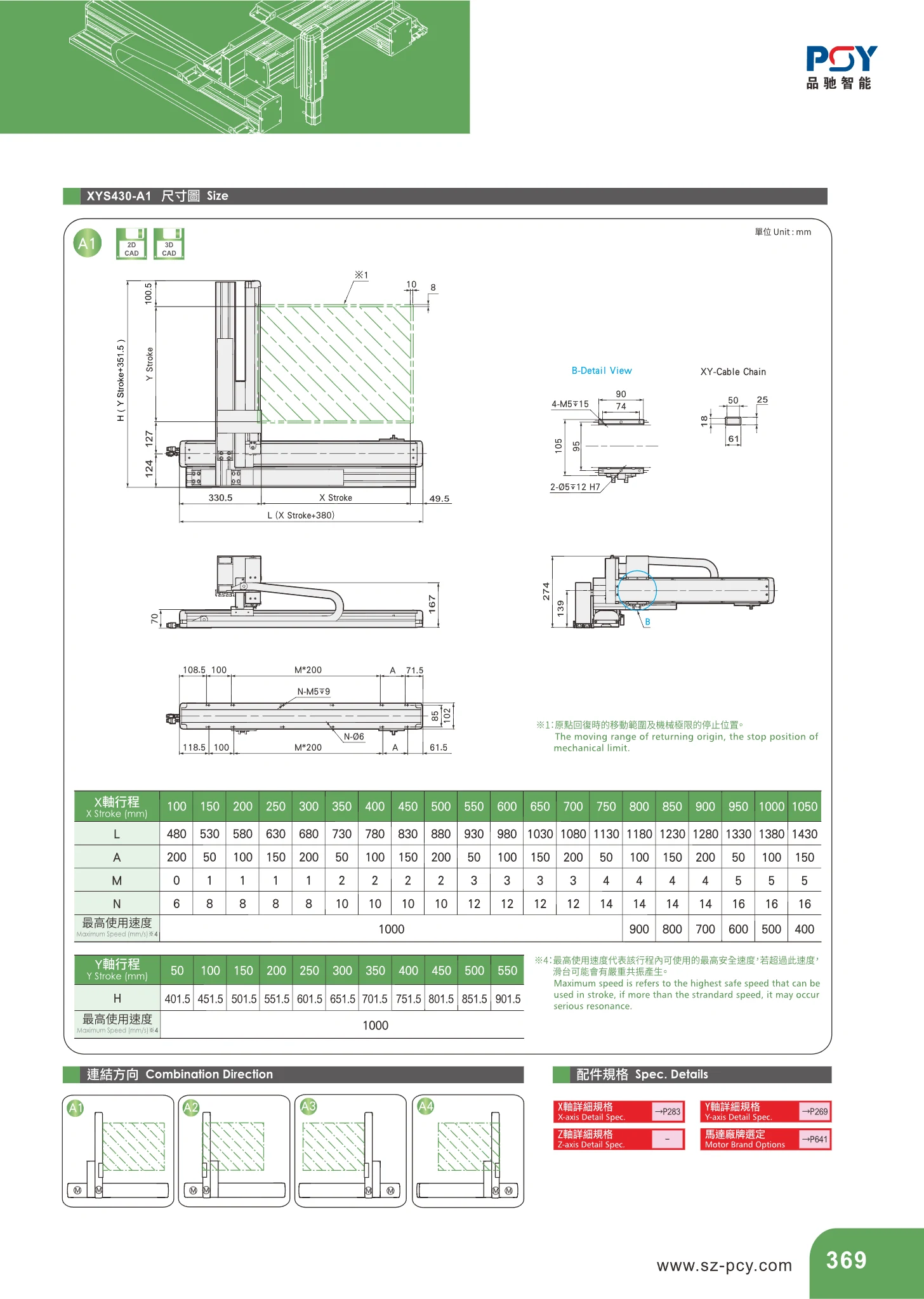
XYS430-A1 Series XY Linear Modules
The XYS430-A1 is a precision linear module with a dual-axis (XY) configuration, an aluminum extrusion body, and built-in XY cable chains. It is suitable for automated applications requiring two-dimensional positioning, such as electronics assembly, inspection, and dispensing. Standard X-axis travel ranges from 100~1050 mm in 50 mm increments. Overall length L varies linearly with travel (L = travel + 380 mm), while the number of mounting holes M and hole diameter N increase in stages as travel increases (M from 0 to 5 and N from 6 mm to 16 mm). The catalog specifies a maximum operating speed of 1000 mm/min. The table has 4-M5×15 threaded mounting holes and a 2.5×15 locating slot. Key overall dimensions are 90/100/105/130/138/143 mm. When selecting a model, consult the table for L, A, M, N, and the corresponding maximum speed based on the required travel.