Linear Module

FX3020H Series Three-Section Aluminum Alloy Slides
Suitable for office equipment, industrial electronic equipment, display shelving, medical equipment, automotive components, and more. Full extension, non-detachable, side-mounted; natural anodized finish. Pull-out: not available.

XYT764-A Series 3-axis
Belt drive. This image is for reference only; see the dimensional drawings for the delivered specifications. Synchronous motion accuracy is not specified for standard linked slides.

SFS-V/W Series Flexible Couplings · Diaphragm Type
Compatible motors include servo motors, stepper motors, and general-purpose motors. Frictional clamping transmits torque without backlash, making these couplings suitable for high-precision control. The body is made of 45# steel, providing high torsional rigidity and high torque transmission. The stainless steel diaphragm accommodates parallel, angular, and axial misalignment and offers good fatigue resistance. The hub design at both ends reduces inertia. The materials and processing table lists the materials and treatments for the body, intermediate shaft, set screws, assembly screws, assembly washers, and diaphragm.
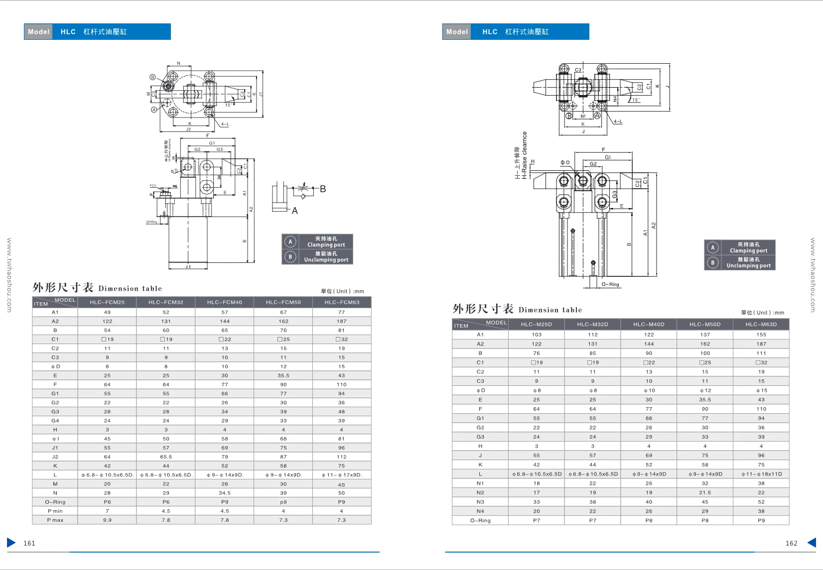
HLC-M Series Linear Modules
The HLC-M series linear modules are available in five bore sizes: 25, 32, 40, 50, and 63 mm. They feature an aluminum-alloy cylinder body and a high-precision guide mechanism, making them suitable for linear motion applications in automation equipment. Their compact design makes installation easy, and they accommodate a range of loads and stroke requirements. The O-ring seal provides effective dust protection.
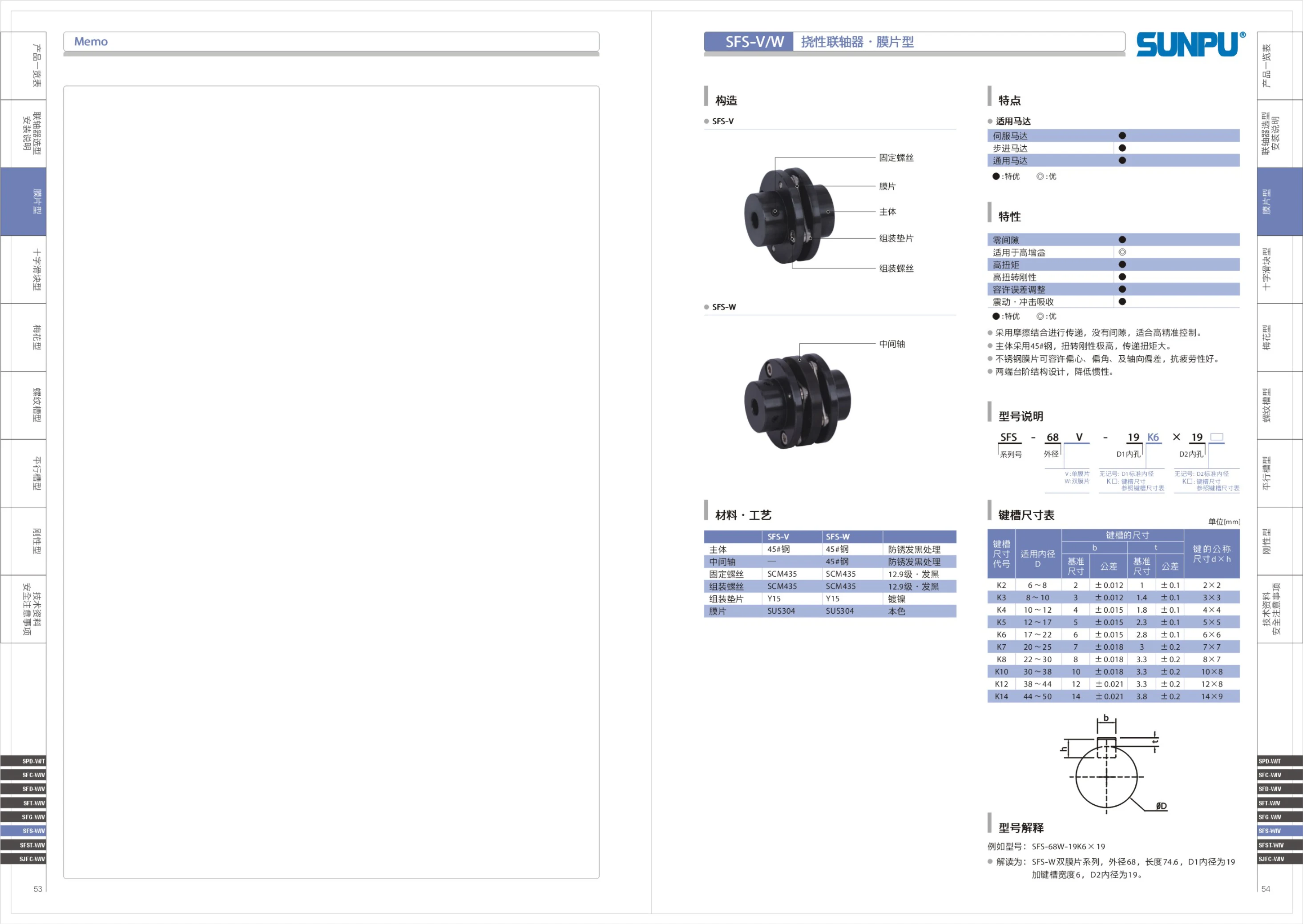
SFS Series Linear Modules
The SFS series of linear modules includes two structural designs: SFS-V and SFS-W. These modules are compatible with servo motors, stepper motors, or general-purpose motors, and are available in premium and standard performance grades to meet different precision and load requirements. Their compact design makes them suitable for linear motion applications in automation equipment.
FGSX/FGSY Series Linear Slides
The FGSX/FGSY series consists of linear slides (linear slide modules). The catalog provides outline and mounting dimensions for each model in the form of dimensional drawings. The series is divided into FGSX and FGSY subseries according to the X and Y structural or mounting orientations. Model numbers consist of a series code (FGSX or FGSY), size code 40, a second size code (40 or 60), and the suffix L. Examples include FGSX40-40-L, FGSX40-60-L, FGSY40-40-L, and FGSY40-60-L. Thus, each 40 size is available with two second sizes (40 / 60) and the corresponding mounting orientation. The series is suitable for linear transfer, positioning, and guidance applications involving small to medium loads and short to medium strokes. Select the configuration based on stroke, load, mounting orientation, and accuracy requirements. Refer to the technical pages of the complete catalog for internal configurations such as guide rails, lead screws, and drive methods.
FGFX/FGFY Series Linear Modules
The FGFX/FGFY series consists of matched linear modules (single-axis actuators): FGFX serves as the X-axis and FGFY as the Y-axis. Together, they can form an XY Cartesian motion unit. The catalog provides outline and mounting dimensions for each size in dimensional drawings. Models are classified by frame size (40 or 60) and the second size designation (40/60 for frame size 40, 50/75 for frame size 60). The fixed L suffix denotes a structural variant of that model, such as a left/right or long configuration. Select the frame size according to load, stroke, and installation space, and refer to the dimensional drawings to confirm mounting hole locations and interface dimensions.
FLX/FLY Series Linear Modules
The FLX/FLY series comprises linear modules and slides used in factory automation equipment. This page provides dimensional drawings for the series' size 200 models. Models shown include FLX200-L, FLX200-R, FLY200-LM, and FLY200-RM. The number 200 denotes the frame size, while L, R, LM, and RM distinguish the left- or right-hand mounting orientation and structural configuration. The catalog page does not provide detailed specifications such as rated load, stroke, or repeatability. When selecting a model, check its overall dimensions and mounting interfaces.
FLBX Series
The FLBX series, including the related FLBY models, is presented in this catalog as full-page dimensional drawings for checking the body outline and mounting interfaces. Each model designation consists of a body code and an orientation code: FLBX100 and FLBY100 identify size 100 bodies for the X and Y directions, respectively, while the suffixes -C / -L / -R indicate center, left, and right mounting orientations (configurations), respectively. When selecting a model, first choose FLBX or FLBY according to the equipment's axis layout, then select the C / L / R orientation based on available mounting space and potential interference. This series page provides dimensional drawings only; refer to the relevant drawing for specific dimensions, mounting hole locations, materials, and accuracy specifications.
FLBY Series Linear Modules
This page provides only an outline dimension drawing and three model designations for the FLBY series: FLBY100-C, FLBY100-L, and FLBY100-R. These are variants of the same size, distinguished by C/L/R. The source does not specify technical parameters such as travel, accuracy, material, load capacity, or mounting dimensions, nor does it provide model coding rules. The specific structural differences between C/L/R are not explained. When selecting a model, consult the outline dimension drawing to verify mounting interfaces, overall shape, and differences between variants, and confirm detailed specifications separately.
FLBDV Series Linear Modules
The FLBDV series comprises linear motion modules (linear stages) for factory automation. The catalog provides dimensional drawings for four sizes: FLBDV25-L-C2, FLBDV40-L-C2, FLBDV60-L-C2, and FLBDV80-L-C2. In the model designation, FLBDV is the series code, 25/40/60/80 indicate four cross-sectional sizes in ascending order, and the suffix -L-C2 identifies the length/configuration designation. When selecting a model, check the mounting hole locations, overall profile, and mounting surface height against the dimensional drawing for the relevant size to ensure compatibility with the machine base and load attachment. This page provides dimensional information only. For performance specifications such as stroke, accuracy grade, allowable load, and maximum speed, consult the other technical pages for this series or contact the manufacturer.
FLD Series Linear Modules
The FLD series linear module catalog provides dimensional drawings for models including FLD40-LM, FLD60-LM, FLD80-LM-2, FLD90-LM-2, and FLD125-LM-2, covering frame sizes 40, 60, 80, 90, and 125. These modules are suitable for linear motion mechanisms in factory automation equipment, with sizes available to suit different space and load requirements. Detailed specifications such as lead, stroke, accuracy, and rated load are not listed on this page. When selecting a model, consult its dimensional drawing and additional technical documentation.
FLSP Series Linear Modules
The FLSP series comprises linear modules (linear actuator units). This catalog page provides dimensional drawings showing the overall profiles and mounting interface dimensions for each size in the series. The series is available in four frame sizes: 40, 60, 80, and 90. Model numbers consist of FLSP, the size number, and a mounting configuration suffix. Suffixes such as L and LM indicate different mounting and drive configurations. Engineers can use the dimensional drawings to check mounting hole locations, body length, and interface positions when selecting a model and designing mating equipment. As this page contains dimensional drawings only, refer to other pages of the complete catalog for specifications such as effective stroke, lead, repeatability, rated load, and motor configuration.
FLTP Series Linear Modules
The FLTP series linear modules from FARAY AUTOMATION (Faray) feature an aluminum profile body with a timing belt or lead screw drive for linear positioning, handling, and sliding motion in automation equipment. This dimensional drawing page lists several models by module size: FLTP40, FLTP60, FLTP80, and FLTP90 correspond to four cross-section sizes, 40/60/80/90, covering applications from small, light-duty to medium-sized, medium-duty systems. Model suffixes distinguish designs and configurations: -LM denotes the basic linear module configuration, -L denotes an alternative design, and the final -2 indicates a configuration variant such as dual sliders or dual outputs. Select the appropriate size based on stroke, load, and installation space, and check the dimensional drawings for the specific stroke and mounting dimensions.
Dovetail Rack-and-Pinion Driven Linear Module
The dovetail rack-and-pinion driven linear module is part of the FARAY (FARAY AUTOMATION) linear motion product line. This series uses a dovetail groove (V-shaped sliding guide surfaces) for guidance and a meshing rack and pinion for linear drive. The rack is fixed to the guide base, while the pinion moves with the carriage. The design offers high structural rigidity, strong load capacity, and extendable travel through joined sections, making it suitable for long-travel, medium- to low-speed, heavy-load handling, positioning, and reciprocating transport applications. Clearance at the dovetail surfaces can be adjusted with a gib to balance guiding accuracy and wear resistance. The drive can be combined with a gearbox, servo motor, or handwheel. Key selection factors include guide size, travel, gear module, rack length, load, and mounting method. This page provides series-level information only; specific models and code combinations are not listed.
LW Series Dovetail Rack-and-Pinion Linear Modules
FARAY LW series dovetail linear modules use a rack-and-pinion drive and offer a high operating frequency, making them suitable for applications requiring fast movement and long travel. The lightweight aluminum alloy body makes them easy to integrate into other equipment. The product range includes standard and long-travel series. Standard models are available with 25×42 or 40×40 table sizes and a choice of single-direction X-axis, bidirectional X-axis, single-direction Z-axis, two-direction X-axis, or three-direction XYZ movement. They are available with a base plate (no designation) or without one (N). The long-travel series builds on the standard design with a specified rail length (in mm) and number of sliders (1 by default; multiple sliders can be specified numerically), enabling longer travel and multi-station loads. The modules use a parallel-motion dovetail design.
FLW Series Linear Modules
The FLW series is identified by the FLW prefix in the catalog and includes X, E, Y, D, Z and other configurations, with size codes including 2542, 4040, 4060 and 4090. The page primarily provides dimensional drawings. Model numbers consist of FLW + a configuration letter + a four-digit size code. These modules are suitable for linear motion and positioning in automation equipment. As the page lists only model numbers and outline drawings, travel, rated load, mounting hole positions and motor configurations should be confirmed using the drawing or specification sheet for the relevant model.
FLXSC Series Linear Modules
The FLXSC series linear modules (linear slides) are shown on this page with dimensional drawings to help verify installation dimensions and select the stroke length. The main model is FLXSC160, with the numerical suffix indicating the stroke. Three stroke options are listed: 100, 200, and 400 (FLXSC160-100, FLXSC160-200, and FLXSC160-400). The overall length increases with the stroke. Select the model according to the travel distance required by the equipment, and use the dimensional drawings to check mounting hole locations, body width, and overall length. Ensure that the interface dimensions match the connected mechanism, coupling, or drive motor. Refer to the corresponding specification table for performance parameters such as repeat positioning accuracy, rated load, and maximum speed.
FLVSC Series Linear Modules
The FLVSC series is a range of linear modules (linear stages) from FARAY AUTOMATION. The catalog provides mounting and overall dimensions for each size in outline dimension drawings. The available documentation covers two stroke versions of the 160 size (body cross-section/guide rail width on the order of 160): FLVSC160-100 and FLVSC160-200, with strokes of 100mm and 200mm respectively. Model numbers consist of the “FLVSC160” base designation followed by the “-stroke” suffix. When selecting a model, use the body length, mounting hole positions, carriage surface dimensions and allowable stroke shown in the outline drawing to plan the mechanism layout and determine the motor mounting method and load capacity. The series is suitable for automated equipment requiring linear reciprocating positioning, handling or pressing. Rated load, maximum speed, repeatability and drive type (screw or timing belt) must be confirmed in the complete catalog; this page provides outline dimensions only for the two stroke versions of the 160 size.
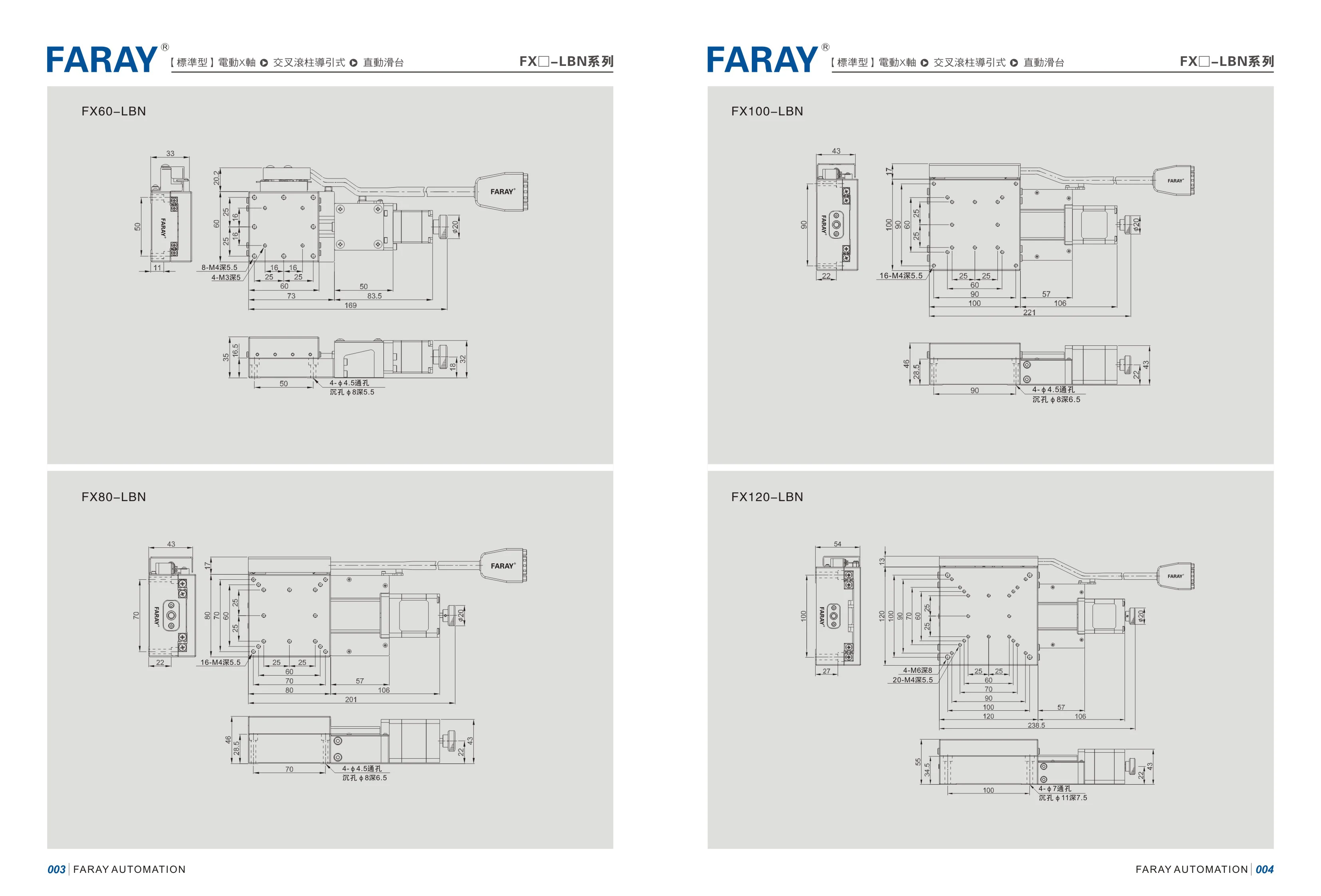
FX Series Linear Modules
The FX series consists of linear modules manufactured by FARAY AUTOMATION. Models are identified by frame size, with common models including FX60, FX80, FX100, and FX120, corresponding to cross-sectional widths of approximately 60/80/100/120mm. They meet linear motion requirements ranging from light to medium-heavy loads. The -LBN suffix is a factory configuration code denoting a standard combination of options, such as guide type, drive mechanism, or mounting and protection features. The series is suitable for linear transfer, positioning, and pressing operations in automated equipment and can be driven by servo or stepper motors. Select the model based on cross-sectional dimensions, effective stroke, load, and speed requirements, then use the configuration suffix to specify the structural combination.
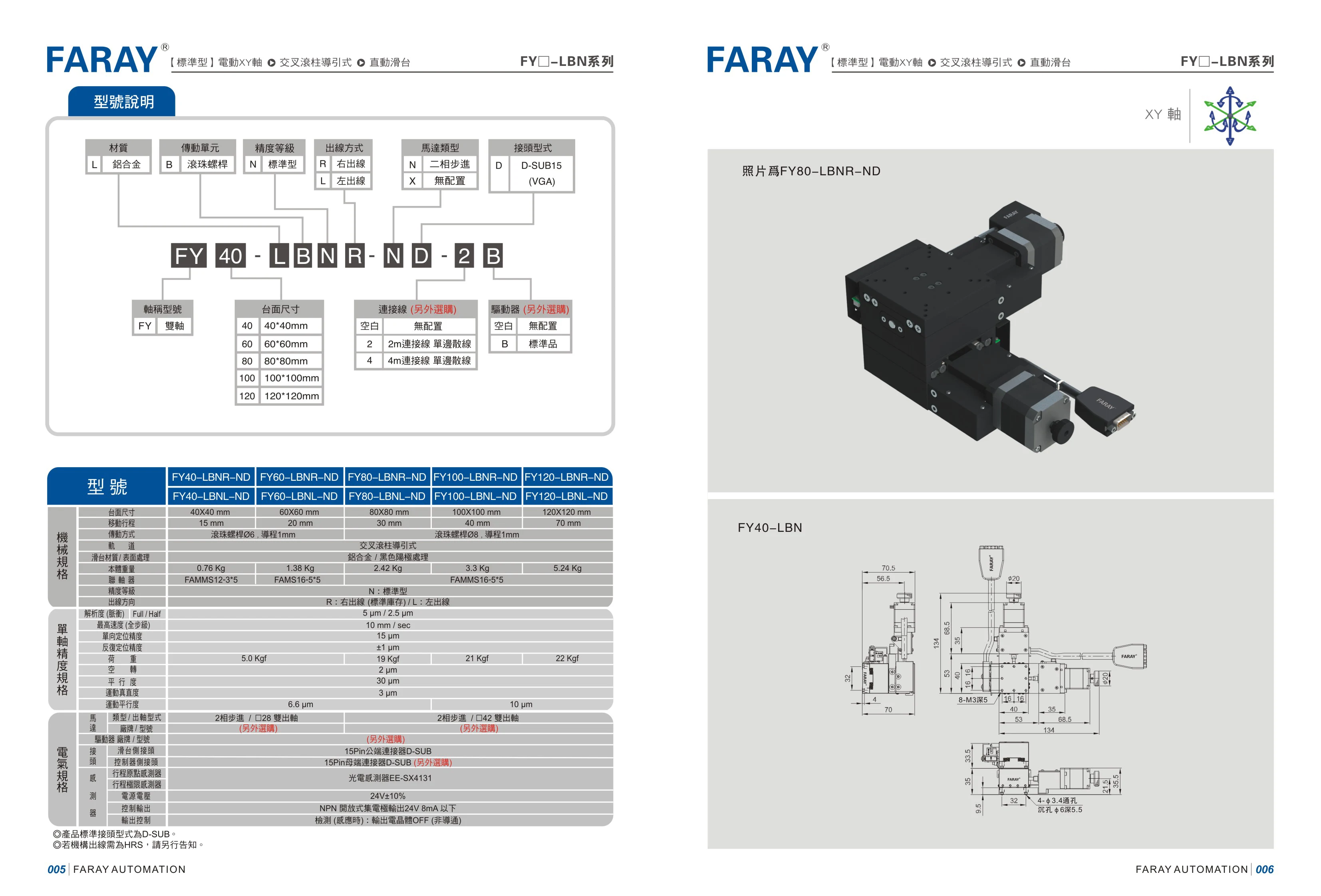
FY Series Linear Modules
FARAY FY series linear modules feature an aluminum alloy profile body. B denotes a ball screw drive, suitable for linear positioning and handling mechanisms in automation equipment. The model table defines codes including material L (aluminum alloy), drive B (ball screw), precision N, cable outlet R/L (right/left), motor N (two-phase stepper)/X (not included), and connector D (D-SUB15/VGA). The examples cover FY40 and FY80 sizes, which can be selected according to available space and load requirements. Refer to the corresponding drawings to confirm travel, lead, and mounting dimensions.
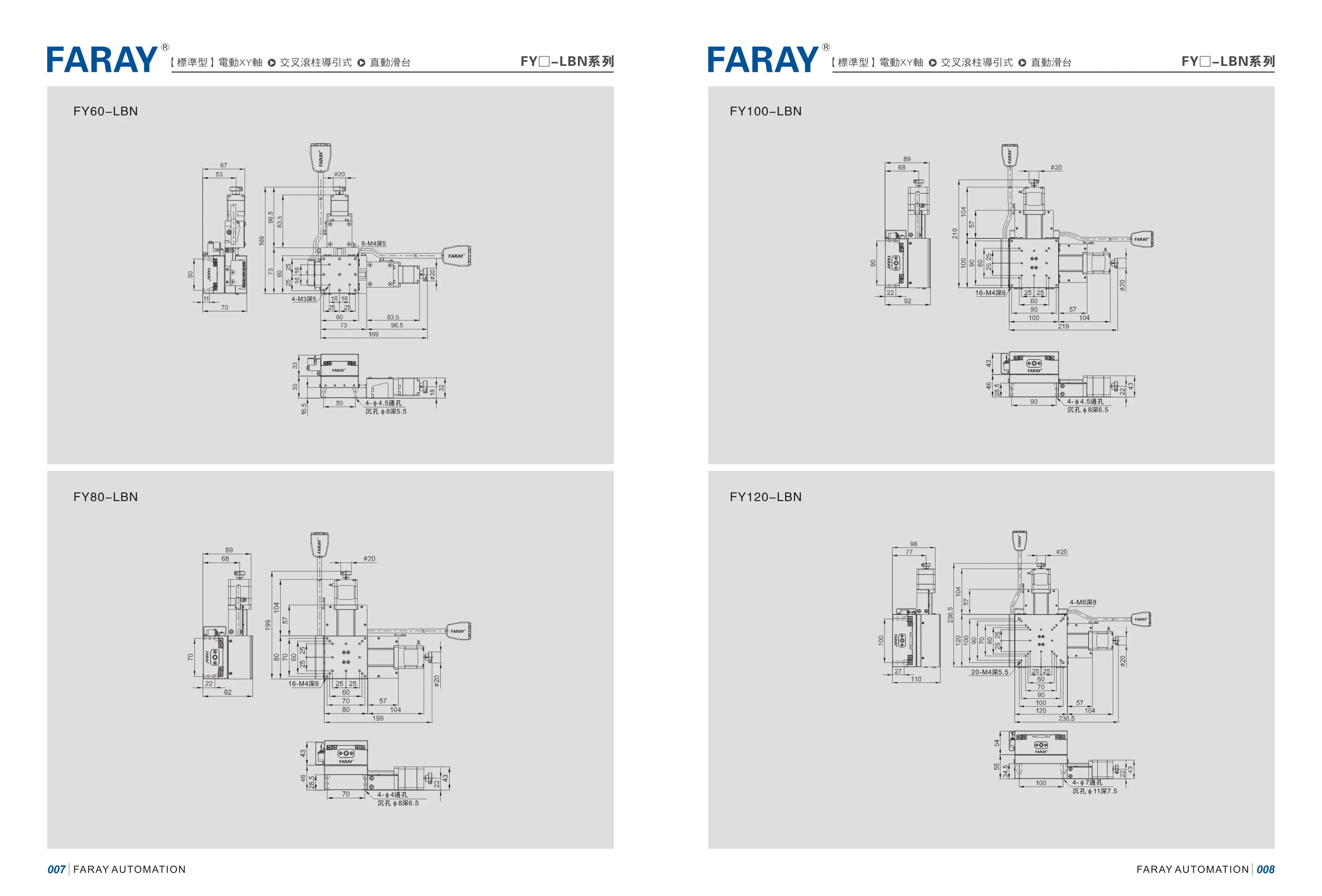
FY Series Linear Modules
FY series linear modules (linear slides) are grouped by base size. The catalog lists four sizes: FY60, FY80, FY100 and FY120. The number corresponds to the module's base/guide cross-sectional width in mm, covering applications from light-load precision positioning to medium- and heavy-load handling. A short suffix distinguishes configurations within each size. The configuration code shown on this catalog page is LBN, denoting the standard configuration for that size. When selecting a module, use the base size to determine the load and rigidity range, then use the suffix to determine details such as stroke, drive type, motor mounting orientation and protection type. Different configurations of the same size share the same mounting interface dimensions, making it easier to standardize equipment structures.
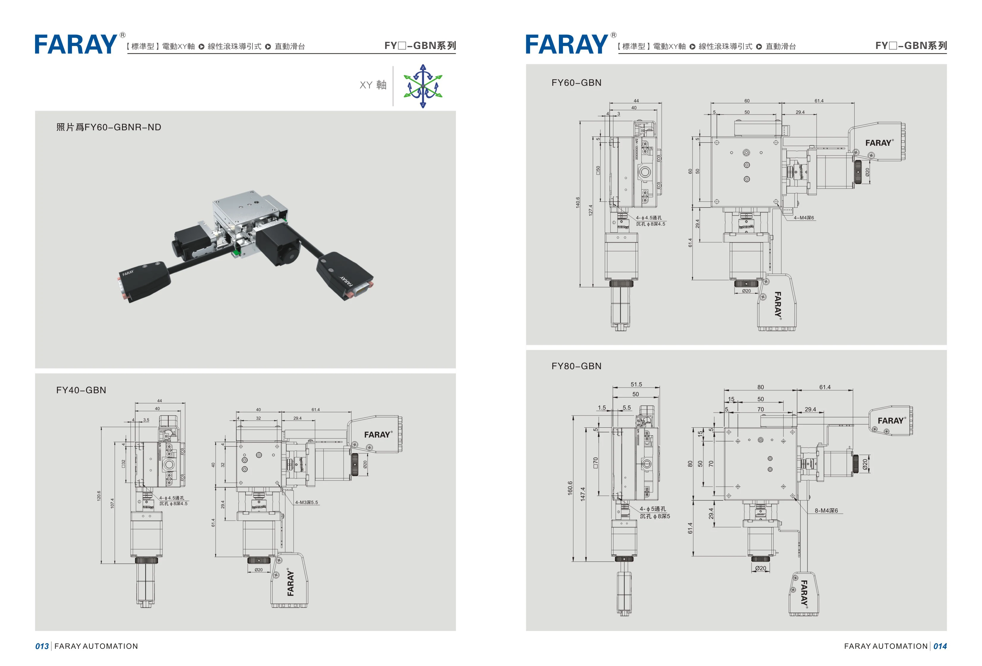
FY-GBN Series Linear Modules
The FY-GBN series is a range of linear modules (linear actuators) from FARAY AUTOMATION. The catalog includes FY40-GBN, FY60-GBN, and FY80-GBN models in three cross-section/frame sizes of 40/60/80 mm, meeting linear motion requirements for different strokes and loads. The series is grouped by frame size, and the suffix “GBN” identifies the structural type. Different drive and mounting configurations are available, along with variants such as FY60-GBNR-ND. These products are suitable for linear handling, positioning, and pressing in automated equipment and can be paired with drive units such as servo and stepper motors.
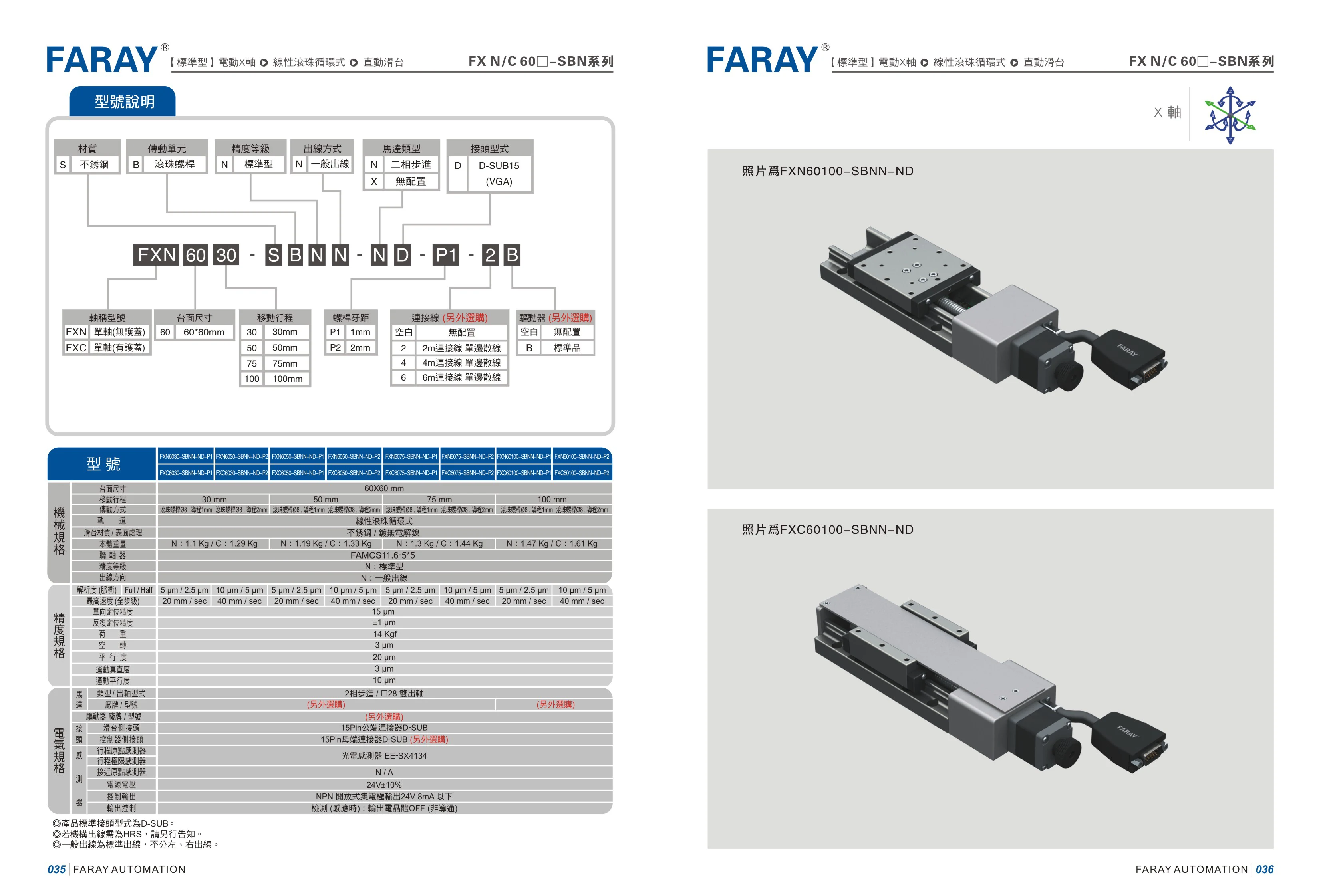
FXN/FXC Series Ball Screw Linear Modules
The FXN/FXC series comprises precision linear modules driven by ball screws. Their bodies are made of stainless steel, with common frame sizes of 60 and 80 and travel lengths of 50mm and 100mm. Modules are ordered using a multi-part code that specifies the material, drive unit, accuracy grade, cable exit, motor type, and connector type in sequence, as in FXN60100-SBNN-ND and FXC8050-SBNN-ND. Motor options are a two-phase stepper motor (N) or no motor (X); connector options are D-SUB15 (VGA) or no connector. These compact, rigid modules provide consistent positioning accuracy and are commonly used for precision linear positioning in automated applications such as electronics assembly, semiconductor equipment, inspection, and material handling.
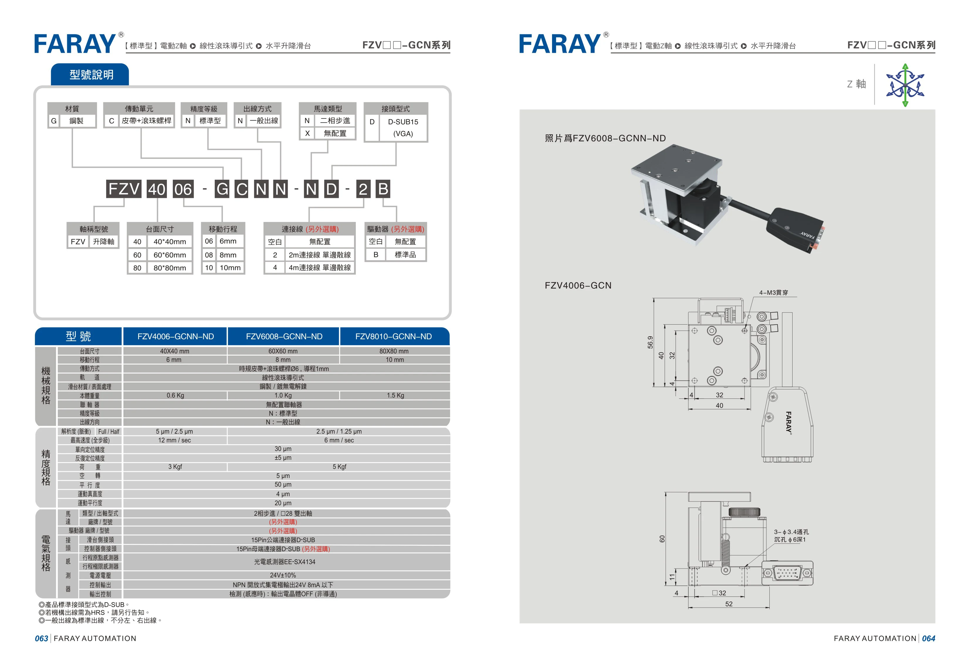
FZV Series Linear Modules
The FARAY FZV series of linear modules includes models such as FZV4006, FZV6008 and FZV8010, with configurations including GCN and GCNN-ND. The listed mechanical specifications include table sizes of 40×40 mm and 60×60 mm, and mounting hole types such as 4-M4 through holes and 4-Ø4.5× through holes. These modules are suitable for linear motion, positioning and handling mechanisms in automated equipment. Table size, mounting holes and configuration can be selected by model code. Model codes consist of FZV + size number + configuration suffix. Specific stroke, accuracy and load ratings should be confirmed against the complete catalog.
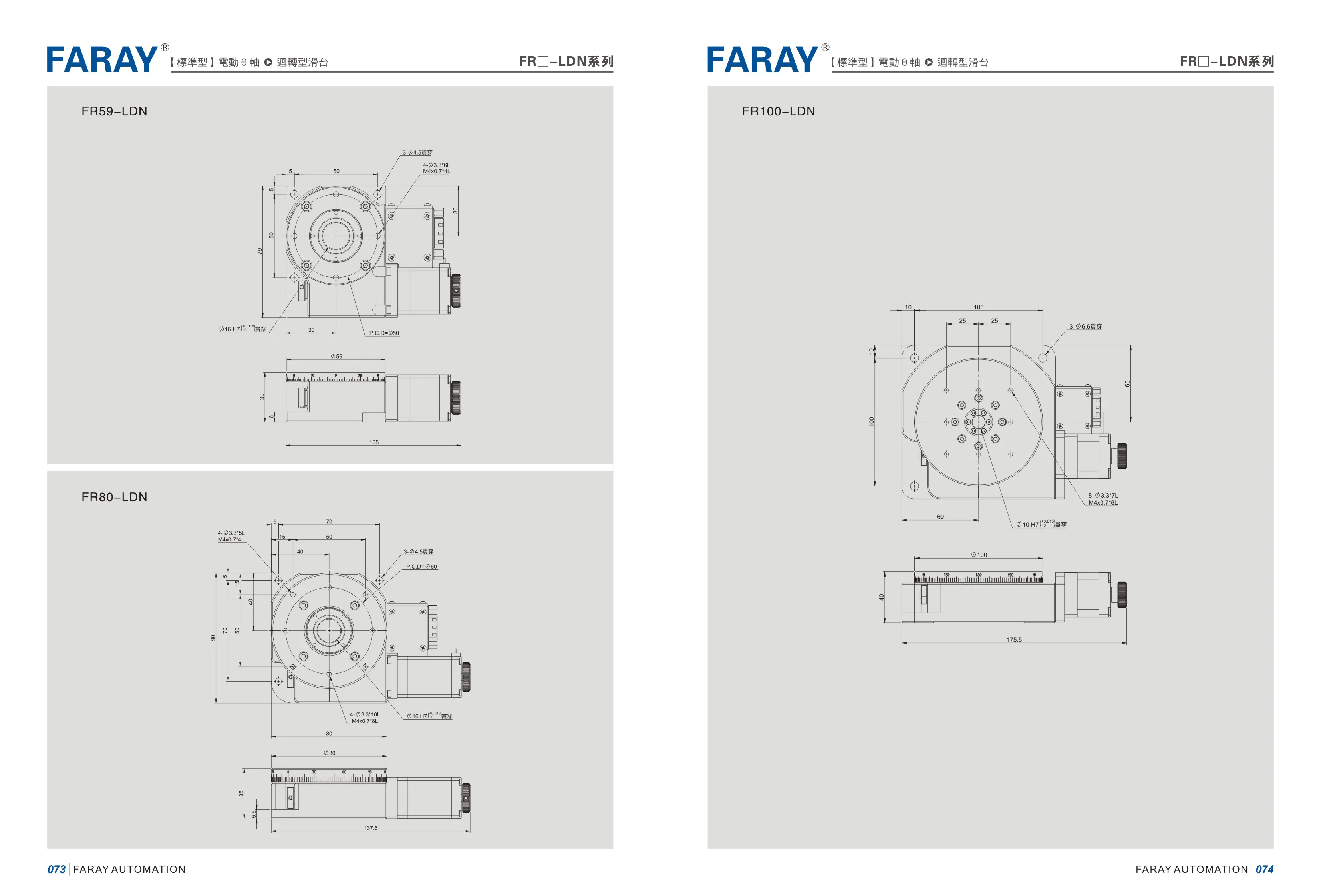
FR-LDN Series Linear Modules
The FR-LDN series comprises linear modules/linear motion units listed in the FARAY AUTOMATION catalog. This page presents three models: FR59-LDN, FR80-LDN, and FR100-LDN, with sizes distinguished by the numbers 59, 80, and 100 in their model identifiers. They are suitable for automated mechanisms requiring reciprocating linear motion. Parameters such as stroke, lead, rated load, repeatability, and motor mounting method are not detailed on this page. Consult the complete catalog and consider actual operating conditions when selecting a model.
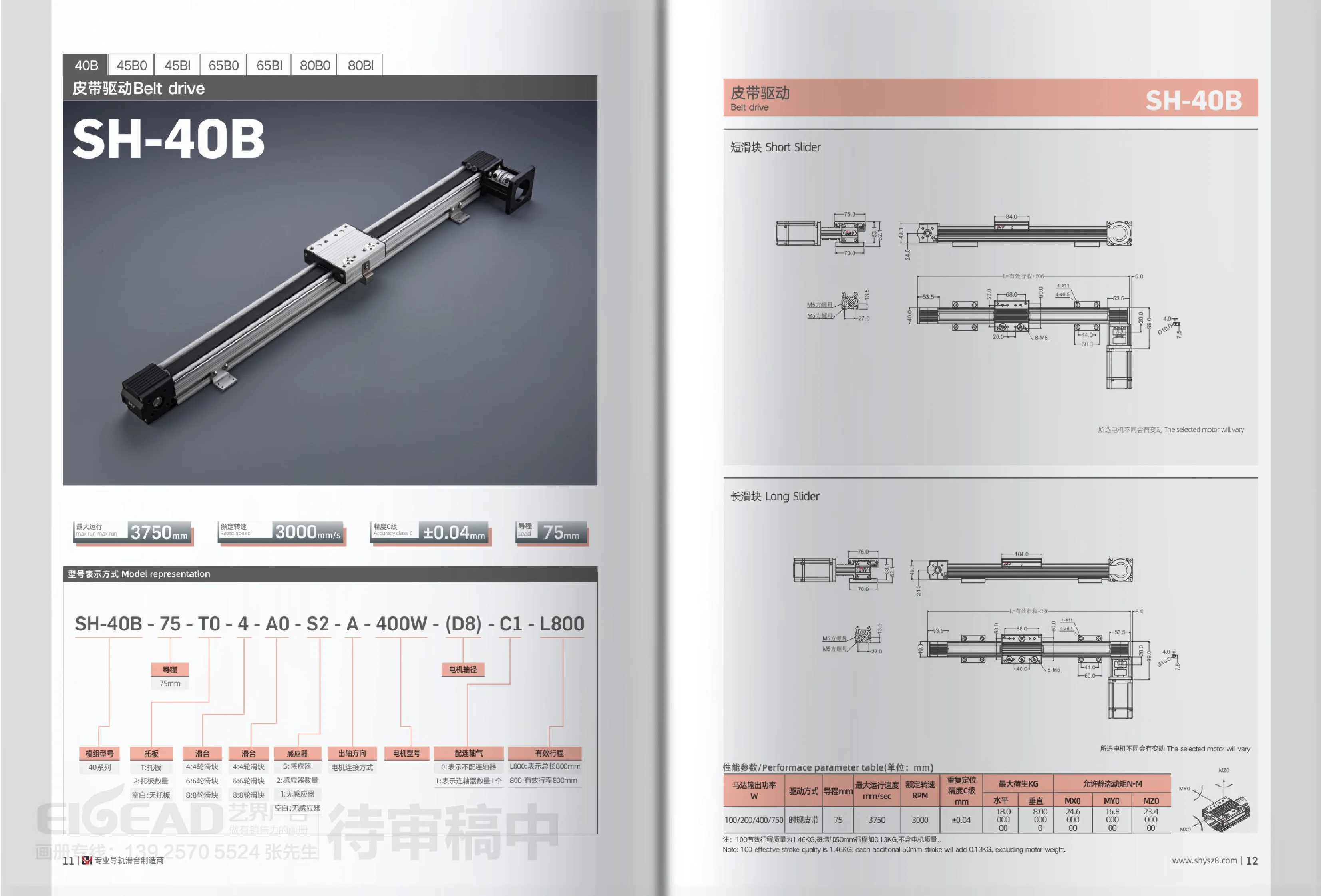
SH-B Series Belt-Driven Linear Modules
The SH-B series comprises timing belt-driven linear modules available in 40B, 45B0/45BI, 65B0/65BI, and 80B0/80BI models. The SH-40B, for example, has a 75mm lead, a maximum operating speed of 3750mm/s, a rated speed of 3000rpm, and Class C repeatability of ±0.04mm. Motor power options are 100/200/400/750W. Maximum load capacity is 18.0kg horizontally and 8.0kg vertically, with allowable static torques of MXD 24.5N·m and MYO 16.8N·m. The model designation includes the main model, lead, carriage plate, slider, sensor, motor connection, motor model, power, shaft diameter, coupling, and length, allowing selection by stroke length and accessory combination. The unit weighs approximately 1.46kg with a 100mm effective stroke, with an additional 0.13kg for every 50mm of stroke. Motor weight is excluded.
SH Series Belt-Driven Linear Modules
SH series belt-driven linear modules feature a timing (synchronous) belt drive and an extruded aluminum body. They are available in a wide range of travel lengths and cross-section sizes, including 40B, 45B0, 45BI, 65B0, 65BI, 80B0 and 80BI. For example, the 40 series has a lead of 75mm, a maximum speed of 3750mm/s, a rated speed of 3000RPM, and Class C repeatability of ±0.04mm. Its maximum load is 18.0kg horizontally and 8.00kg vertically, with allowable static torques of MXD 24.5N·m and MYO 16.8N·m. It can be fitted with 100/200/400/750W motors. The module weighs approximately 1.46kg at 100mm effective travel, with an additional 0.13kg for every 50mm of travel (excluding the motor). The model number combines codes for the module series, lead, carriage plate, number of carriage wheels, motor mounting configuration, sensor, motor model, motor power, motor shaft diameter, accuracy class, and overall length/effective travel.
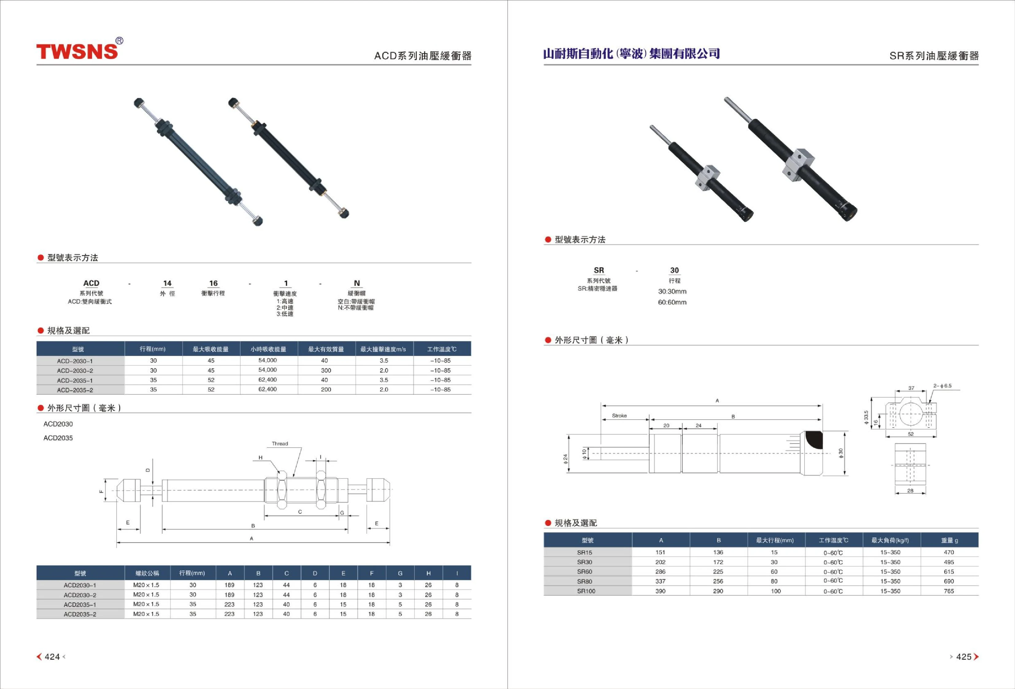
SR Series Linear Modules
The SR series is a range of linear modules (slides) from SNS Automation (Ningbo) Group Co., Ltd. It includes five models classified by effective stroke: SR15, SR30, SR60, SR80, and SR100. All models share the same cross-sectional profile and mounting interfaces. The model numbers correspond to their maximum strokes of 15, 30, 60, 80, and 100 mm, respectively. The series has an operating temperature range of 0-60℃, maximum loads ranging from 15-350 kgf, and body weights of approximately 470-765 g, increasing with model size. Two key mounting and overall length dimensions are specified: A is 151/202/286/337/390 mm, and B is 136/172/225/256/290 mm. These dimensions can be used to check available installation space and select a model. The modules are suitable for short-stroke reciprocating linear motion in automated applications such as electronics assembly, packaging, and inspection. Select a model according to the required stroke, installation space, and load, and machine mounting holes according to the dimensional drawings in the catalog.
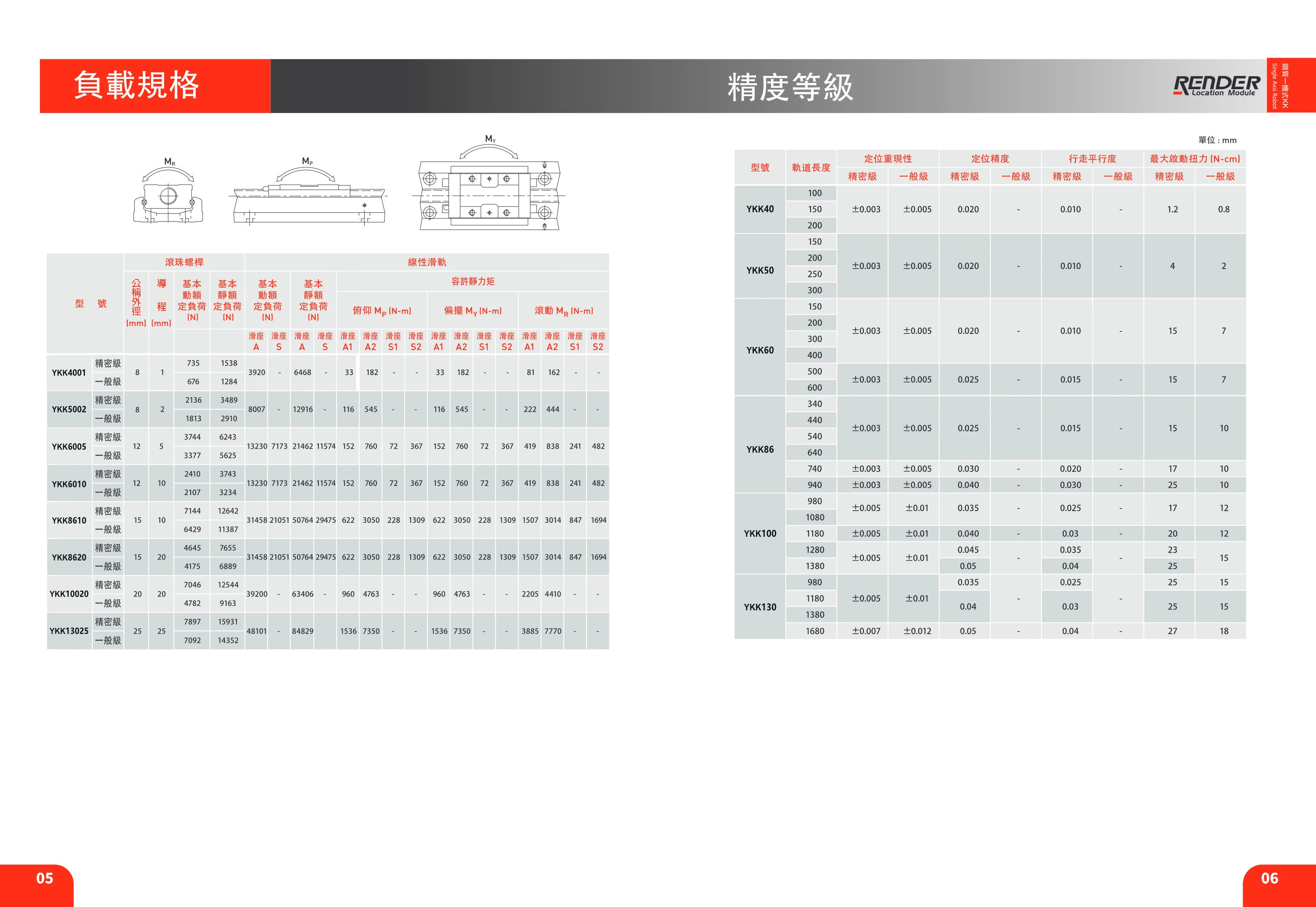
YKK Series Linear Modules
The YKK series consists of semi-enclosed ball screw linear modules that integrate an aluminum extrusion base, precision ball screw, linear guide, coupling, and sensor mounting slots. They are designed for precision linear transfer, positioning, and pushing operations in automated equipment. Standard models include six cross-sectional sizes: YKK40, YKK50, YKK60, YKK86, YKK100, and YKK130. Track lengths are available in increments from 100mm to 1680mm. Maximum stroke varies by model and track length (for example, the YKK40-100 has a maximum stroke of 35mm, while the YKK100-1380 has a maximum stroke of 1346mm). Positioning repeatability is ±0.003~±0.007mm, positioning accuracy is ±0.005~±0.012mm, and travel parallelism is 0.020~0.05mm; accuracy decreases slightly as track length increases. The body includes mounting slots for limit switches and can be fitted with sensors such as the Omron EE-SX671 and PANASONIC GX-F12A / GX-F12A-P for home and limit detection at both ends of travel.
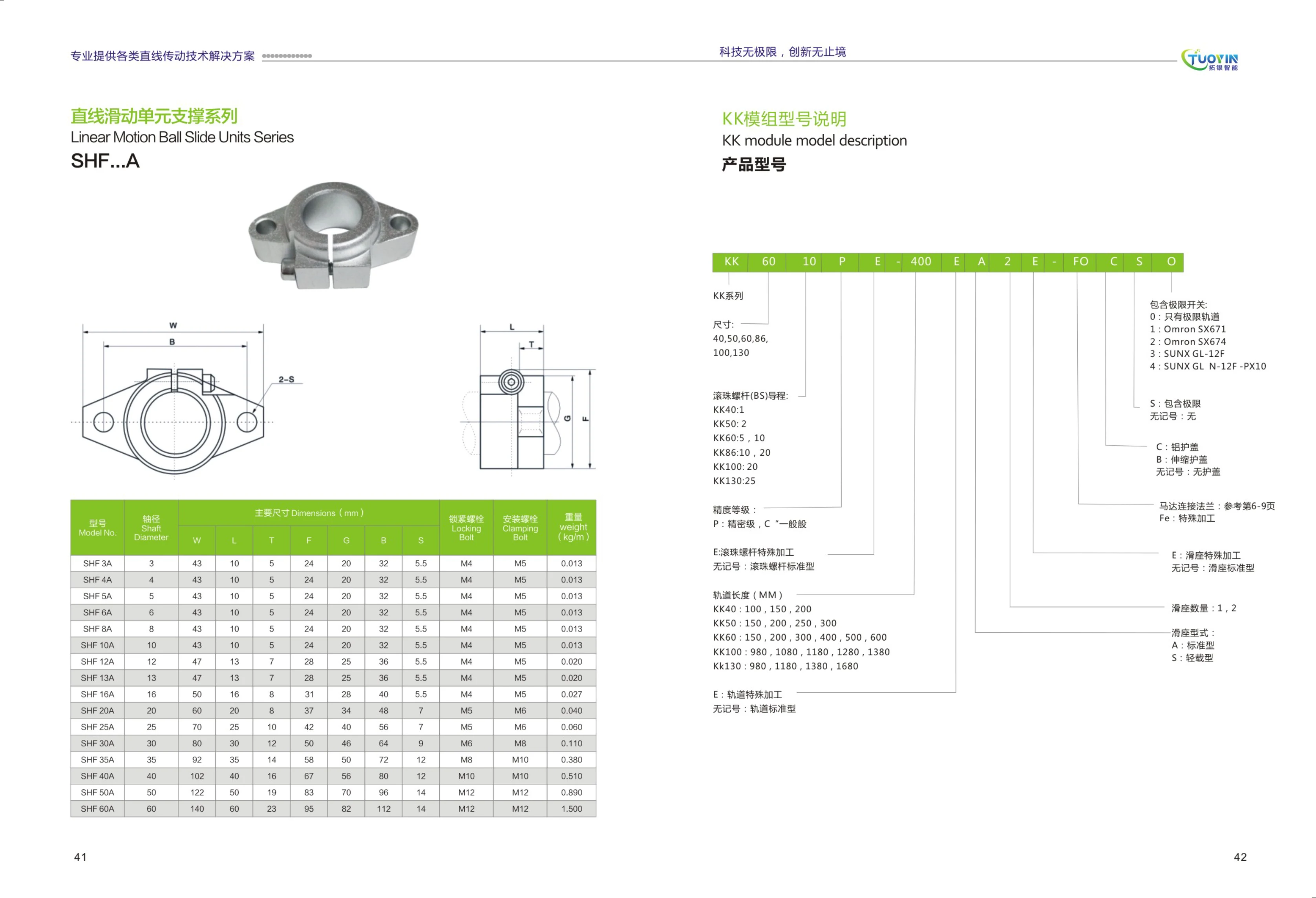
KK Module
The KK module is a series of ball-screw-driven linear modules, available in sizes including KK40, KK50, KK60, KK86, KK100, and KK130. Leads range from 1 to 25 mm, and rail lengths from 100 to 1,680 mm. Precision grades include precision (P) and standard (C), with repeatability of up to ±0.003 mm. Various limit-switch configurations are supported. The carriage is available in standard (A) or light-load (S) versions, with one or two carriages. Suitable for automation equipment, precision positioning, material handling, and more.
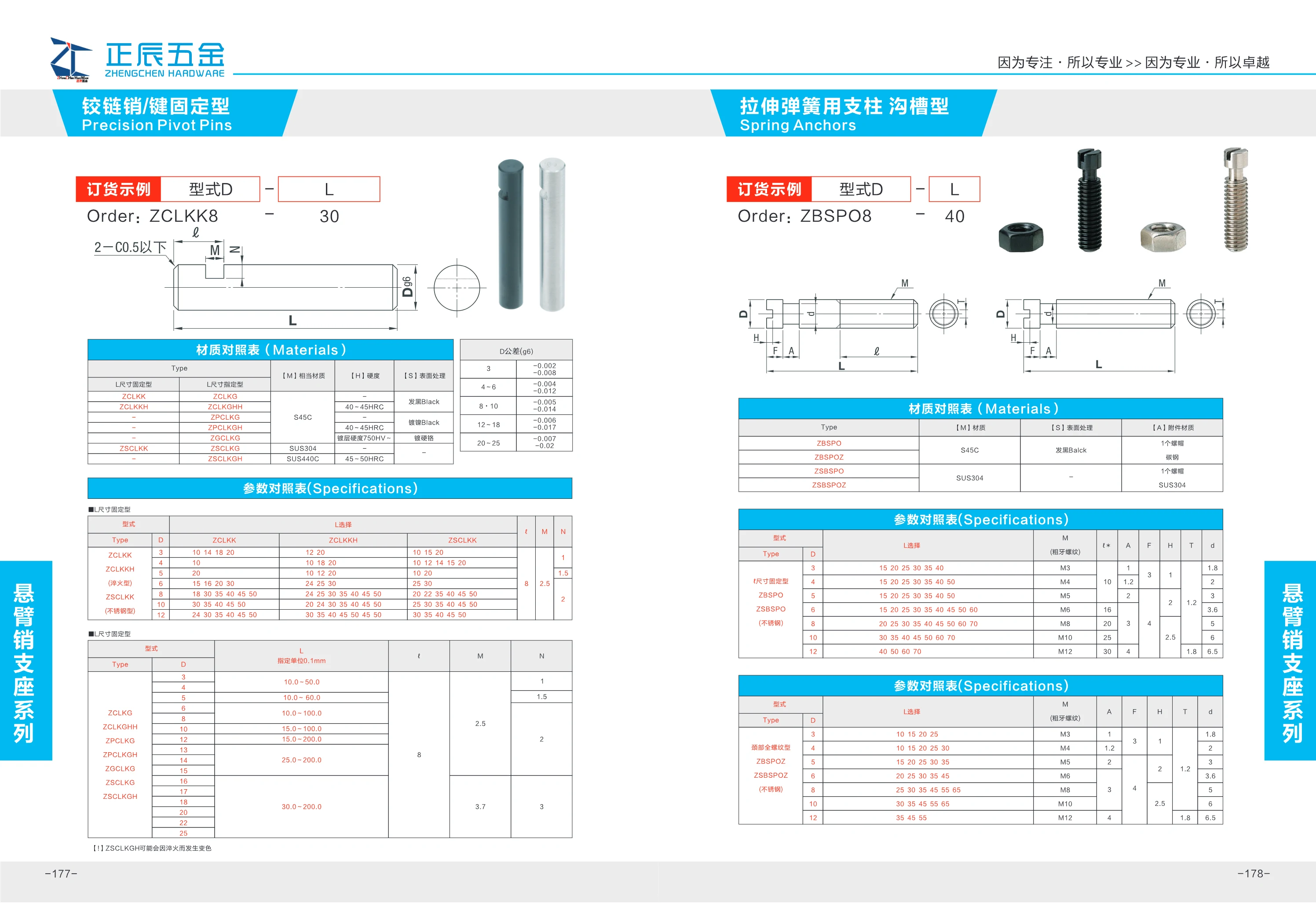
ZCLKK Series Linear Modules
The ZCLKK series linear modules are available in two versions: fixed L dimension (ZCLKK8) and specified L dimension (ZCLKKH). An ordering example is ZCLKK8-30, where 30 may indicate the length or stroke. The material is not specified, but metal is typically used. Suitable for guiding linear motion in automation equipment.
FLBX60/FLBY60 Series Linear Modules
The FLBX60/FLBY60 series is a range of size 60 linear modules from FARAY AUTOMATION. The catalog page provides dimensional drawings for four basic configurations, distinguished by mounting/structural arrangement and travel: FLBX60-C, FLBY60-C, FLBX60-L, and FLBY60-L. FLBX60 and FLBY60 are two alternative carriage/guide rail arrangements, while C and L denote two length (travel) variants of each arrangement. Select a model based on the load, travel, and available mounting space. Refer to the corresponding dimensional drawing for overall length, carriage mounting hole positions, travel, height, and other dimensions, and check for interference with the host assembly, coupling/motor mount, and cable carrier before ordering. This page contains dimensional drawings only; refer to the series specification page for repeatability, maximum speed, allowable load moments, motor configurations, and other specifications.
FLBX80 Series
The FLBX80 series consists of components for factory automation equipment. This page provides outline dimension drawings. The series includes two types, FLBX80 and FLBY80, each available in -C, -L, and -R variants, for a total of 6 models. This catalog page only shows outline dimensions and corresponding models; it does not list technical specifications such as material, accuracy grade, or rated load. For model selection, consult the dimension and specification tables in the complete catalog.
FLBY80 Series Linear Modules
The FLBY80 series consists of linear module bodies (single-axis slides) for factory automation. The catalog lists two orientation codes, FLBX80 and FLBY80, each available in C, L, and R variants. These typically indicate the mounting position of the motor or drive end (center, left, or right) or differences in structural orientation. This page provides only dimensional drawings for checking the outline, mounting surfaces, and interface locations of each variant. Specific technical parameters such as effective stroke, lead, repeatability, rated load, allowable moment, and maximum speed are not listed; consult the specification tables on other pages for the same series when selecting a model. The known model structure is “FLB + orientation letter (X/Y) + 80 + mounting variant (C/L/R).” For a non-standard stroke or special mounting arrangement, specify the complete model number along with the stroke and accessory sections when ordering.
FLGX40 Series Linear Modules
The FLGX40 series is available in three configurations: C, L and R (FLGX40-C, FLGX40-L and FLGX40-R). The catalog provides outline drawings showing the overall profiles and mounting dimensions of each configuration for use in product selection and equipment design. All three configurations share the same basic specifications but differ in their arrangement (centered, left-facing or right-facing), allowing flexible selection based on motor, cable outlet or mounting surface orientation where installation space is limited. Different configurations can also be used at different stations on the same machine. When selecting a module, refer to the dimensional drawing for the relevant configuration to verify mounting hole locations, overall height and width, and the interface with the driven component. Allow sufficient space for travel and clearance. This page contains dimensional drawings only and does not list performance parameters such as rated load, travel or accuracy grade. Consult the series specification page before making a final selection.
FLGX60 Series Linear Modules
The FLGX60 series is a size 60 linear motion module/linear slide offered by FARAY AUTOMATION. The catalog provides dimensional drawings for three configurations: FLGX60-C, FLGX60-L and FLGX60-R. C/L/R generally distinguish the mounting orientation or cable outlet/interface position (center, left-facing and right-facing). All three share the same external profile and mounting dimension references. Select the C/L/R variant based on available space and cable routing. The remaining cross-sectional dimensions, effective stroke and mounting hole locations are common to the same size. Refer to the complete catalog specifications and dimensional drawings for the effective stroke, lead, repeatability, rated load and other parameters.
FLWFV25 Series Linear Motion Modules
The FLWFV25 series consists of linear motion modules (linear stages) for factory automation. Available in mirror-image L and R configurations, they support symmetrical left-right installation and can be selected to suit the motor shaft, wiring, and operating-face orientation. The catalog lists FLWFV25-L and FLWFV25-R separately, each with its own dimensional drawing for checking table dimensions, mounting hole locations, body profile, and surrounding clearance. The catalog page does not provide detailed specifications such as travel, lead, accuracy grade, or rated load. For product selection, consult the complete dimensional drawings and ordering instructions to determine the effective travel, motor mounting method, limit switches, and accessory configuration.
FLWFV60/FLWFDV60 Series Linear Modules
FLWFV60 and FLWFDV60 are two variants in the same FARAY AUTOMATION series. Each is available in L and R versions based on orientation and mounting configuration, giving four models: FLWFV60-L, FLWFV60-R, FLWFDV60-L, and FLWFDV60-R. The catalog provides dimensional drawings showing the outline and mounting hole locations for each model to assist with selection and installation. The 60 in the model number denotes the 60 frame size (body width class). The series is suitable for linear motion, positioning, and material handling mechanisms in factory automation equipment and can be used with servo or stepper motors and their corresponding drives. The supplied page contains dimensional drawings only; detailed specifications such as stroke, lead, accuracy grade, rated load, and maximum speed are not listed. Refer to the full catalog when selecting a model.
FLWFX60/FLWFV60 Series Linear Modules
The FLWFX60/FLWFV60 series comprises size 60 linear modules (electric linear slides). The series includes two structural types, FLWFX60 and FLWFV60, each available in two symmetrical versions according to mounting and cable exit direction: L (left) and R (right). The four basic models are FLWFX60-L, FLWFX60-R, FLWFV60-L, and FLWFV60-R, enabling symmetrical layouts and mirrored installation on either side of automated equipment. The catalog provides dimensional drawings showing the external and mounting interface dimensions of each model. These can be used to determine mounting hole positions, carriage and slide profiles, and how they fit with other components. When selecting a model, first choose the X or V structure based on load, stroke, and available installation space, then select the L or R direction to suit the equipment layout. These modules are typically used with servo or stepper motors, couplings, and sensors. Actual stroke, lead, positioning repeatability, maximum load, and maximum speed should be checked against the relevant specification page or confirmed with the manufacturer.
FLX100 Series Linear Modules
The FLX100 series is a range of linear motion modules (linear slides) from FARAY AUTOMATION. Page 69 of the catalog provides dimensional drawings for three configurations: FLX100-C, FLX100-L, and FLX100-R. All three share the same FLX100 base cross-section and mounting interfaces but differ in drive-end arrangement and mounting orientation, allowing a choice of left-side, right-side, or center shaft placement in confined spaces. Select the specific model based on stroke, lead, load, and mounting orientation. The dimensional drawings can be used to verify the body length, slider mounting hole positions, and interface dimensions. This page provides dimensional information only. For detailed specifications such as rated load, maximum speed, repeatability, and motor configuration, see the other pages for this series.
FLX120 Series Linear Modules
The FLX120 series consists of size 120 linear modules (linear stages). The catalog page provides dimensional drawings for three configurations—FLX120-C, FLX120-L, and FLX120-R—distinguished by their mounting and drive arrangements. Each has a different body orientation and cable outlet/drive position, allowing designers to select the configuration that suits the equipment layout. The series uses 120 as its cross-sectional size designation. Selection is based primarily on dimensions shown in the drawings, including body width, mounting hole locations, stroke, and slider platform dimensions. This page contains dimensional drawings only and does not specify technical values such as stroke, lead, accuracy grade, allowable load, or speed. Confirm the selection using the stroke and specification tables in the complete catalog. During installation, note the differences in body orientation among the C/L/R configurations to avoid interference with surrounding mechanisms.
FLX125 Series Linear Modules
The FLX125 series comprises size 125 linear motion modules (linear stages) in the FARAY AUTOMATION catalog. Dimensional drawings show the mounting envelope and interface dimensions for three structural variants: FLX125-C, FLX125-L, and FLX125-R. These drawings support model selection, installation space planning, and interface verification during equipment design. The three variants use the same size 125 main body with different structural and mounting configurations, typically a standard configuration and left- and right-hand mirror-image configurations. They accommodate different installation orientations for linear handling, positioning, and pressing in automated equipment. Refer to the dimensional drawings on this page to determine mounting hole locations, overall dimensions, and interface dimensions. Travel, lead, accuracy grade, drive method, and motor configuration are not listed on this catalog page and must be confirmed with the manufacturer.
FLX160/FLY160 Series Linear Modules
The FLX160/FLY160 series linear modules have a frame size of 160 and are available in two designs: FLX and FLY. The catalog identifies each configuration by its main model and mounting orientation: FLX160 is available in L (left) and R (right) cable exit/mounting orientations, while FLY160 has corresponding LM and RM variants. The supplied page contains dimensional drawings for the series, showing the outlines, mounting hole locations, and interface dimensions for all four configurations: FLX160-L, FLX160-R, FLY160-LM, and FLY160-RM. These drawings help equipment designers verify installation clearances and design base plates or adapter plates. The modules provide reciprocating linear motion in automated equipment, carrying a slider to position tooling, fixtures, material handling devices, dispensing mechanisms, and other equipment along a linear path. They are suitable for 3C assembly, lithium battery, photovoltaic, packaging, and general custom automation lines. Selection should take into account travel, load, speed, mounting orientation (L/R/LM/RM), and module mounting dimensions. For specific travel and performance parameters, refer to the specification tables in the complete catalog.
FLX40 Series Linear Modules
The FLX40 series comprises linear modules (linear stages) for factory automation. This catalog page provides dimensional drawings for the series, covering two body configurations: FLX40 and FLY40. Three variant codes, C, L, and R, identify six models: FLX40-C, FLX40-L, FLX40-R, FLY40-C, FLY40-L, and FLY40-R. The 40 in the model number is the size designation. Select the FLX or FLY configuration and the C/L/R variant based on the cross-sectional dimensions and body profile, together with the required travel, load capacity, mounting space, and motor mounting orientation. Then use the dimensional drawings on this page to check the body length, mounting hole locations, and surrounding clearance to ensure proper fit with the machine frame and connecting components. For travel, accuracy, rated load, and other specifications, refer to the subsequent specification pages for this series.
FLX50 Series Linear Modules
The FLX50 series comprises linear modules (linear slides) for factory automation equipment. Page 51 of the catalog provides outline dimensional drawings showing the overall and key mounting dimensions of the FLX50 and FLY50 subseries. The models shown are divided into C, L, and R variants according to their mounting or output shaft configuration: FLX50-C, FLX50-L, FLX50-R, FLY50-C, FLY50-L, and FLY50-R. These correspond to different motor and drive orientations, allowing selection based on space constraints and mounting direction. The 50 in the model name indicates the nominal series size, with a slide/profile width of approximately 50 mm. When selecting a model, check the mounting hole positions, travel range, and interface dimensions against the corresponding outline drawing. The supplied page contains only outline dimensional drawings; it does not specify travel, accuracy, load, speed, or other parameters, nor does it provide the complete model coding rules. For detailed specifications, refer to the other pages for this series or contact the manufacturer.
FLX60 Series Linear Modules
The FLX60 series consists of size 60 linear modules. This catalog page provides dimensional drawings and lists three configuration codes: FLX60-C, FLX60-L, and FLX60-R. The C, L, and R suffixes typically distinguish motor mounting positions or cable exit directions. Select a configuration based on the available installation space and direction of travel. This page does not provide performance parameters such as stroke, lead, accuracy, load capacity, or speed. Confirm specific dimensions using the corresponding dimensional drawings and technical documentation. The FLY60-C/L/R drawings shown on the same page represent a separate group and are not included in this series' SKUs.
FLX70 Series Linear Modules
The FLX70 series is a range of size 70 linear modules from FARAY AUTOMATION. The catalog provides dimensional drawings for three configurations: FLX70-C, FLX70-L and FLX70-R. These correspond to different body configurations and motor mounting orientations: C is the standard/compact configuration, L has a left-side shaft output or left-facing mount, and R has a right-side shaft output or right-facing mount. When selecting a model, confirm the body configuration code, effective travel, lead, motor mounting method, and whether accessories such as a protective cover are required. Refer to the dimensional drawing for the relevant model for overall length, width and height, mounting hole locations, slider platform dimensions and travel range. The series is commonly used for linear positioning and transfer in automated equipment for electronics assembly, inspection, dispensing and material handling.