Linear Module — Page 2
FLX80 Series Linear Motion Components
The FLX80 series comprises linear motion components used in factory automation equipment. This catalog page presents dimensional drawings for six configurations or mounting variants: FLX80-C, FLX80-L, FLX80-R, FLY80-C, FLY80-L, and FLY80-R. The C/L/R suffixes distinguish different structures or mounting orientations within each series. Dimensions, stroke, load, accuracy, and materials should be verified against the corresponding dimensional drawings and subsequent specification pages. These components are suitable for automated mechanisms requiring linear guidance, positioning, or reciprocating motion.
FLX90 Series Linear Modules
The FLX90 series consists of size 90 linear motion modules. This page is a model index for their dimensional drawings. The catalog distinguishes three configurations by motor mount and output shaft orientation: C (center), L (left), and R (right). The related FLY90-C/L/R models are shown alongside them on the same drawing for easy comparison of mounting dimensions and overall profiles during selection. The series is suitable for linear transfer, positioning, and pressing mechanisms in automated equipment used in electronics, semiconductors, packaging, lithium batteries, and other industries. This page provides only the model index and drawing numbers; it does not list parameters such as specific stroke, lead, accuracy grade, rated load, or maximum speed. Selection must be confirmed against the stroke sections and mounting hole locations on the corresponding dimensional drawing page. For the complete ordering code, including stroke, protection, and motor configuration, refer to the ordering code guide on the series selection page.
FLY120 Series Linear Modules
The FLY120 series comprises 120-size linear motion modules in three configurations: FLY120-CM, FLY120-LM, and FLY120-RM. Each offers a different motor mounting position and output direction, allowing selection based on available installation space and cable routing. All three share a 120 mm class cross-section. This page provides dimensional drawings for checking mounting hole positions, overall dimensions, and clearance with surrounding mechanisms. First select the required configuration (CM/LM/RM), then confirm the effective stroke, lead, accuracy grade, and motor configuration. The source does not specify technical parameters such as stroke, repeatability, or rated load. For actual specifications, refer to the relevant specification page or the manufacturer's technical documentation.
FLY40 Series Linear Modules
The FLY40 series comprises FARAY AUTOMATION 40-size linear modules and electric linear slides. With a cross-section approximately 40mm wide, the integrated profile and guide rail design delivers highly rigid, low-noise reciprocating linear motion. The series has three basic motor mounting configurations: C (center), L (left), and R (right). Additional models with M and B configurations are also available, including CM, CB, LM, LB, and RM. These products are widely used in factory automation for handling, positioning, pushing, and inspection. This catalog page provides only dimensional drawings for each model. Refer to the corresponding specification sheets for travel, lead, rated load, allowable moment, and repeatability.
FLY50 Series Linear Modules
The catalog provides outline dimensional drawings for the FLY50 series linear modules (linear stages), showing their mounting envelopes and interface dimensions. The series has three basic configurations based on motor position: C (center-mounted motor), L (left-mounted motor), and R (right-mounted motor). Variants with the M suffix offer an alternative motor/drive configuration (FLY50-CM, FLY50-LM, FLY50-RM). Select the C/L/R configuration according to the available installation space and motor orientation, and verify the connection dimensions against the mounting hole locations, travel endpoints, and body dimensions shown in the drawings. This section provides outline dimensional drawings only; it does not specify travel, lead, accuracy grade, rated load, maximum speed, or other parameters. Consult the relevant specification page or contact us before making a selection.
FLY60 Series Linear Modules
The FLY60 series is a range of linear modules (linear slides) from FARAY AUTOMATION. The catalog presents the series in overall dimensional drawings, with three basic configurations—C, L, and R—based on the body structure and motor mounting orientation. These are further developed into variants including CM, CB, LM, LB, and RM. The same page also lists the structurally similar FLX60 subseries (FLX60-C / FLX60-L / FLX60-R). When selecting a model, first use the configuration code to determine the body dimensions and mounting hole positions, then verify specifications such as actual stroke, lead, and repeatability. Dimensions in the drawings are given in mm. The catalog does not provide a specification table or pricing for this series. Consult the relevant specification page or the manufacturer for the available stroke ranges, accuracy grades, and compatible motors.
FLY90 Series Linear Modules
The FLY90 series comprises size 90 linear motion modules (slides), presented in the catalog as outline dimension drawings. The series is available in three basic configurations based on drive and mounting position: C (center), L (left), and R (right). Three M-suffix variants, FLY90-CM, FLY90-LM, and FLY90-RM, are also available, allowing the motor and drive components to be arranged to suit limited installation space. The same page lists the structurally similar FLX90-C/L/R variants for comparison with the FLY90 series. These pages contain only outline dimension drawings and do not specify effective travel, lead, repeatability, rated load, maximum speed, or other parameters. Consult the specification tables in the complete catalog before selecting a model. During installation, use the dimensions and mounting hole locations shown in the drawings to align the module with the equipment mounting surface.
FRS60-L Series Linear Module
The FRS60-L is a linear module in the FARAY catalog. This page (page 97) provides an overall dimension drawing showing the module’s outline, mounting hole locations, and interface dimensions to help engineers plan equipment layouts and installation fits. This catalog page does not include a detailed performance specification table, so specific technical parameters such as rated load, stroke, lead, repeatability, and maximum speed should be confirmed using other pages for this series or the manufacturer’s technical manual. In the model designation, FRS is the series code, 60 indicates the size or cross-section class, and L identifies a structural or length variant. When selecting a model, first determine the size based on available installation space and stroke requirements, then check the motor mounting arrangement and configuration options such as the coupling and screw lead. Use the mounting hole spacing and carriage or slide dimensions in the drawing to verify the mechanical design.

FX2020H Series Linear Modules
The FX2020H series is a compact linear module (electric slide) identified by the model format “FX2020H-[specified length]”. Available specified lengths are 60, 70, 90, 100, 200, 300, 400 and 500 mm, with corresponding effective strokes of 30, 40, 50, 60, 120, 120, 240 and 300 mm. Users can select the model suffix that matches the stroke required by their equipment. The catalog provides five sets of overall and mounting dimensions, A, B, C, D and F, as well as rated load parameters calculated for 2 sliders, for checking mounting hole positions and load capacity. For the smaller 60~100 sizes, dimensions A and C are not specified; only B, D and F are provided. Complete dimensions are given for sizes 200 and above. As the specified length increases, dimension F rises from 25 mm to 145 mm, dimensions B and D from 30 mm to 370 mm, and dimensions A and C from 85 mm to 235 mm. Select the appropriate size using the dimension table and taking into account the required stroke, installation space and load.
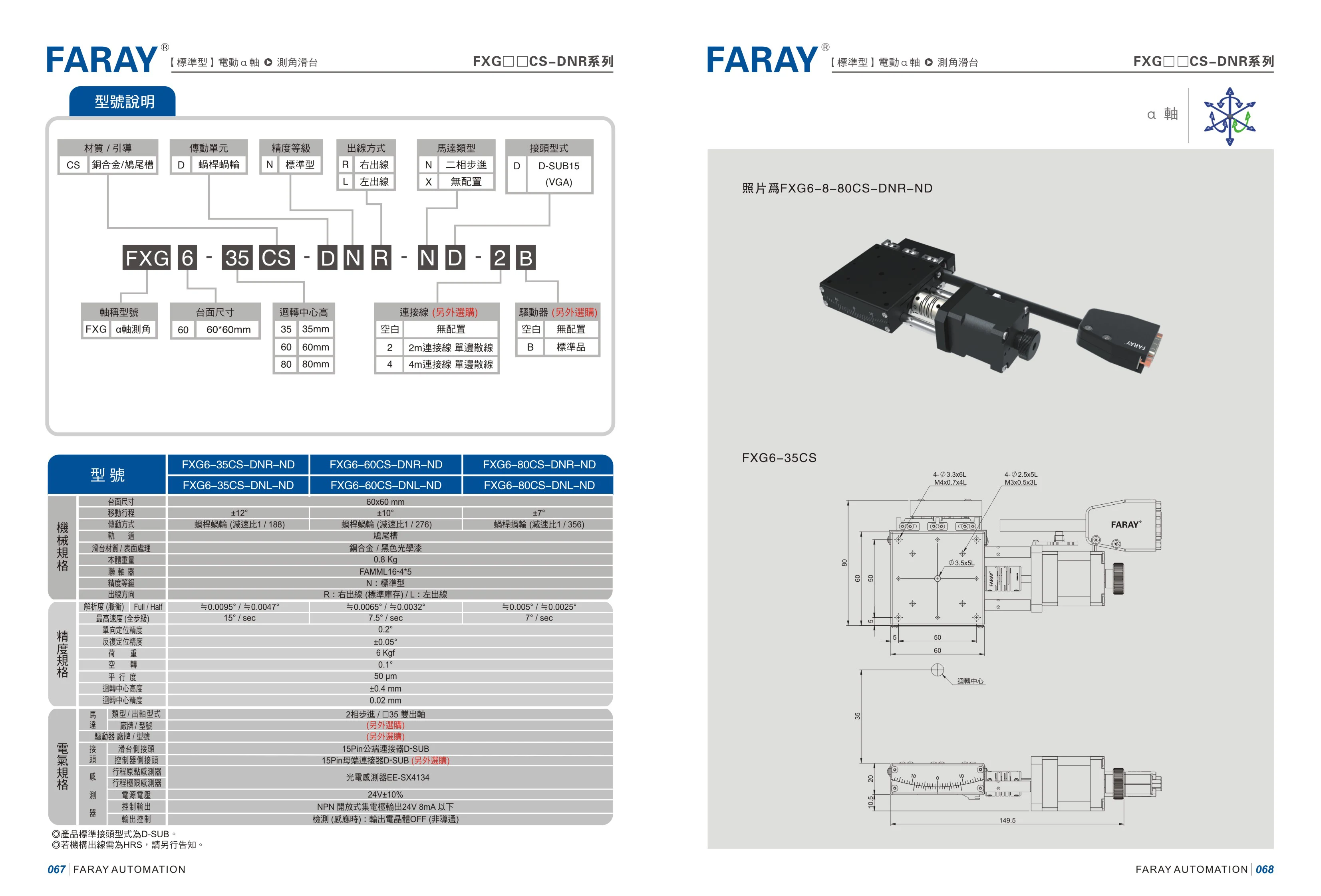
FXG6 Series Linear Modules
The FARAY FXG6 series comprises linear modules available in sizes including 35, 60, and 80. Their modular design accommodates different drive and accessory options, making them suitable for linear transfer, positioning, and other factory automation applications. Model codes specify options such as size, drive type, and accessories, as in FXG6-8-80CS-DNR-ND. Refer to the detailed specification tables in the catalog for parameters such as stroke, lead, and accuracy.
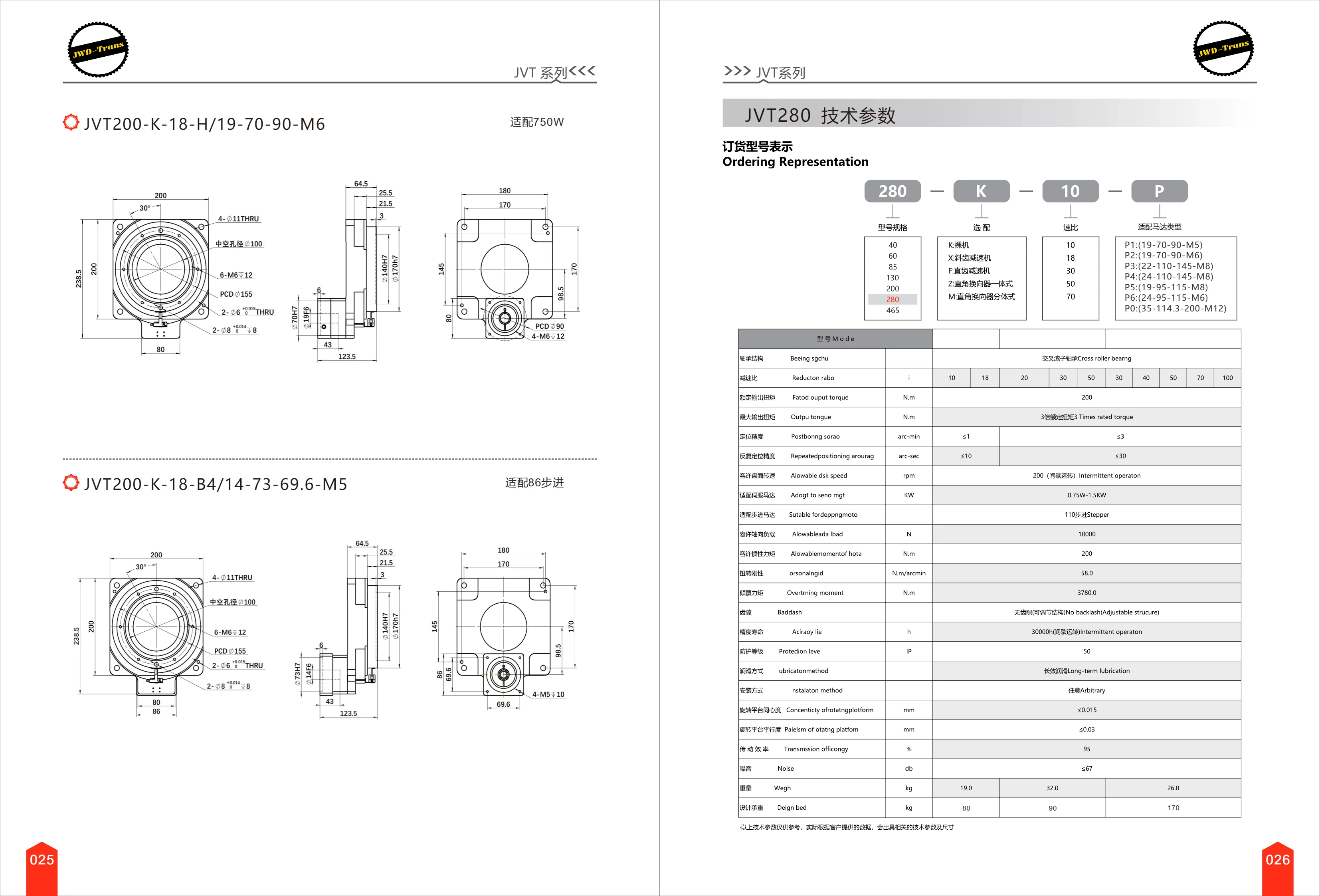
JVT200 Series Linear Module
The JVT200 Series is a compact linear motion module designed for precision positioning and material handling in industrial automation. It is compatible with 750 W servo motors or size 86 stepper motors, and is available with various stroke lengths and mounting interfaces. Model options include the drive mechanism (such as a ball screw or timing belt) and motor connection dimensions to suit different applications. With its sturdy construction and high positioning accuracy, the module is widely used in electronics assembly, packaging machinery, CNC machine tools, and other fields.

PCB85 Series Single-Axis Linear Module
The PCB85 series single-axis linear module (belt-driven single-axis slide) uses a 46mm-wide timing belt and one 20×15 linear guide rail. It offers a maximum travel of 3800mm and a maximum speed of 2000mm, and is compatible with 400W/750W servo motors. Three reduction ratios are available: 5:1, 7:1, and 10:1, with corresponding leads of 40.00mm, 28.57mm, and 20.00mm. Effective travel is selectable from 100–3800mm in 100mm increments. Multiple folded motor mounting orientations are supported, including left, right, upper left, upper right, lower left, and lower right, as well as use as a synchronized driving axis in gantry systems. The module is suitable for long-travel, high-speed automated handling and positioning applications.

PCH10 Open-Loop Stepper Single-Axis Module
The PCH10 open-loop stepper single-axis linear module integrates a Ø16mm ball screw and a dual-row linear guide (2D×18, 1 rail) and is driven by an open-loop stepper motor. It is suitable for precision linear positioning, material handling, dispensing and other applications in automation equipment. Maximum stroke: 1050mm; maximum speed: 533mm/s; maximum static torque: 3N·m. Screw lead options are 05(5mm), 10(10mm), 20(20mm) and 32(32mm). Effective stroke is customizable from 50~1050mm in 50mm increments. Mounting options include exposed motor and motor folded down, left or right. A parameter table provides the corresponding L/A/M/N overall dimensions and total weight (KG) for each configuration. Model codes follow the sequence: base model-screw lead-stroke-specification code-motor specification-controller-accessories.
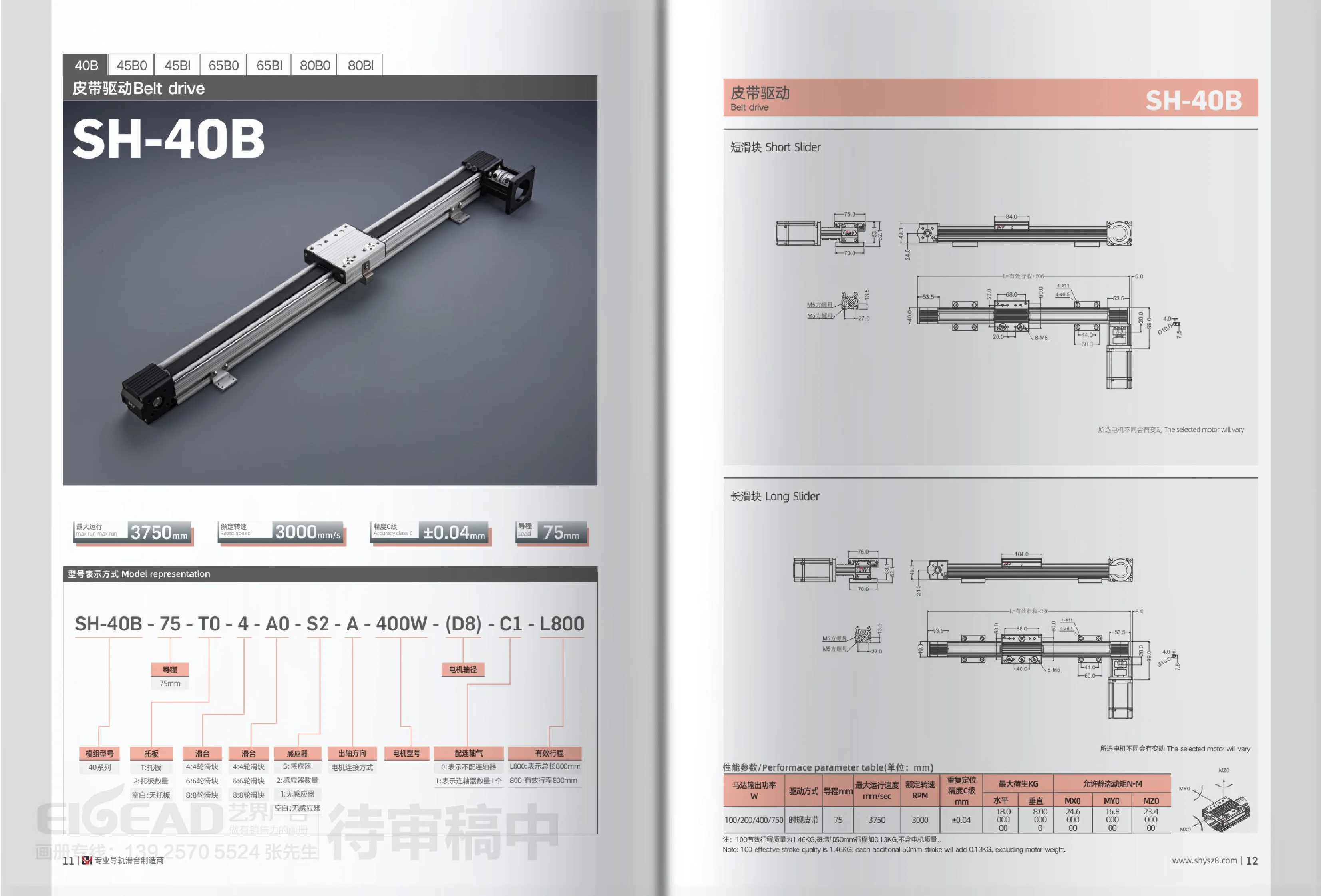
SH-40B Series Belt-Driven Linear Module
The SH-40B series is a timing belt-driven linear module (linear slide) built with a 40-series aluminum profile and a roller carriage as standard. It balances speed and load capacity for long-travel automation applications such as high-speed handling, dispensing, and assembly. The timing belt drive has a 75mm lead, a maximum operating speed of 3750mm/s, and a rated speed of 3000RPM. Optional 100W/200W/400W/750W servo or stepper motors are available, with repeat positioning accuracy of ±0.04mm (Class C). Maximum payload is 18kg horizontally and 8kg vertically; allowable static torque values include MXD 24.5 and MYO 16.8. The modular body can be configured with a mounting plate (T), a 4/6/8-wheel carriage, sensors (S, with quantity options), a coupling (C), and more. Both travel and overall length can be customized (for example, L800 indicates an overall length of 800mm, while 800 indicates an effective travel of 800mm). A unit with 100mm effective travel weighs approximately 1.46kg, with an additional 0.13kg for every 50mm of travel (excluding motor weight).
SH-40B Series Belt-Driven Linear Modules
The SH-40B series belt-driven linear module uses a timing belt drive and an aluminum extrusion body with a 4/6/8-wheel carriage. It is suitable for long-stroke, high-speed handling and positioning applications. It features a 40-series cross-section, a 75mm lead, a maximum operating speed of 3750mm/sec, a rated speed of 3000rpm, and C-grade repeatability of ±0.04mm. Maximum load capacity is 18kg horizontally and 8kg vertically, with allowable static moments of approximately 24.5N·M for MXD and 16.8N·M for MYO. Optional 100W/200W/400W/750W motors and accessories such as support plates, sensors, and couplings are available. Length can be customized by overall length L or effective stroke. A 100mm effective stroke weighs approximately 1.46kg, with an additional 0.13kg for every 50mm added, excluding the motor. The same platform is also available in 45B, 65B, and 80B sizes.
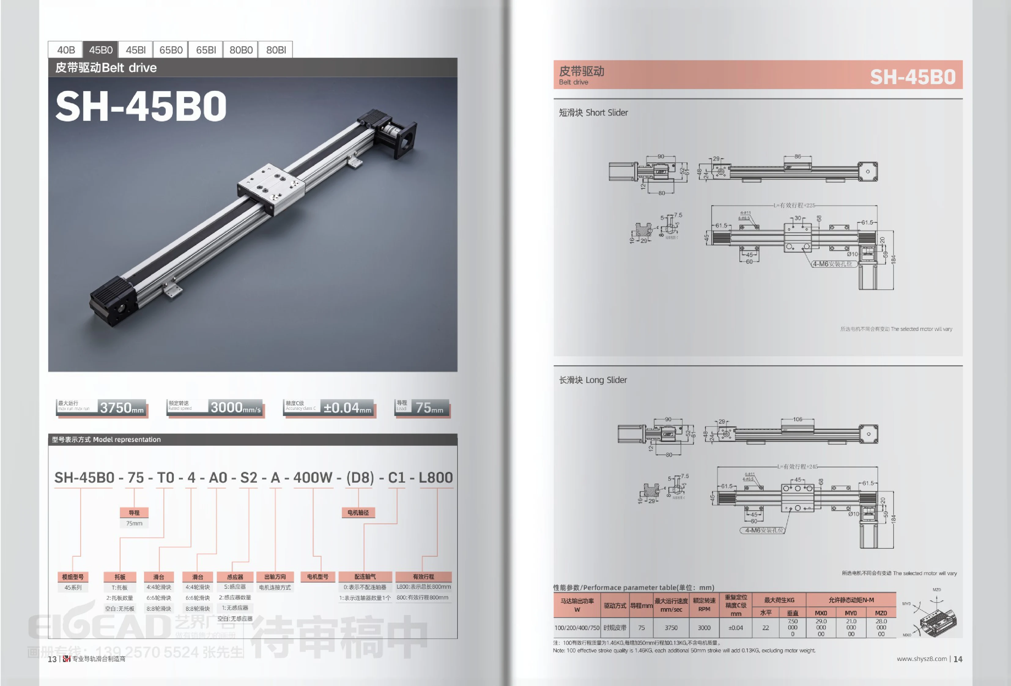
SH-45B0 Series Belt-Driven Linear Modules
The SH-45B0 series is a size 45 belt-driven linear module using a synchronous timing belt, suitable for high-speed handling and positioning over longer strokes. It has a standard lead of 75mm, motor power options of 100/200/400/750W, a maximum speed of 3750mm/s, a rated speed of 3000RPM, positioning repeatability of ±0.04mm (Class C), and a maximum load of 22kg. Allowable static torques are MX0 750N·M, MY0 29.0N·M, and MZ0 21.0N·M. The module can be configured with different mounting plate options (T/blank), wheel sliders (4/6/8 wheels), sensor and coupling quantities, motor shaft diameters (D8, etc.), and effective stroke L values. It weighs 1.46kg at an effective stroke of 100mm, with an additional 0.13kg for every 50mm of stroke, excluding the motor.
SH-45BI Series Belt-Driven Modules
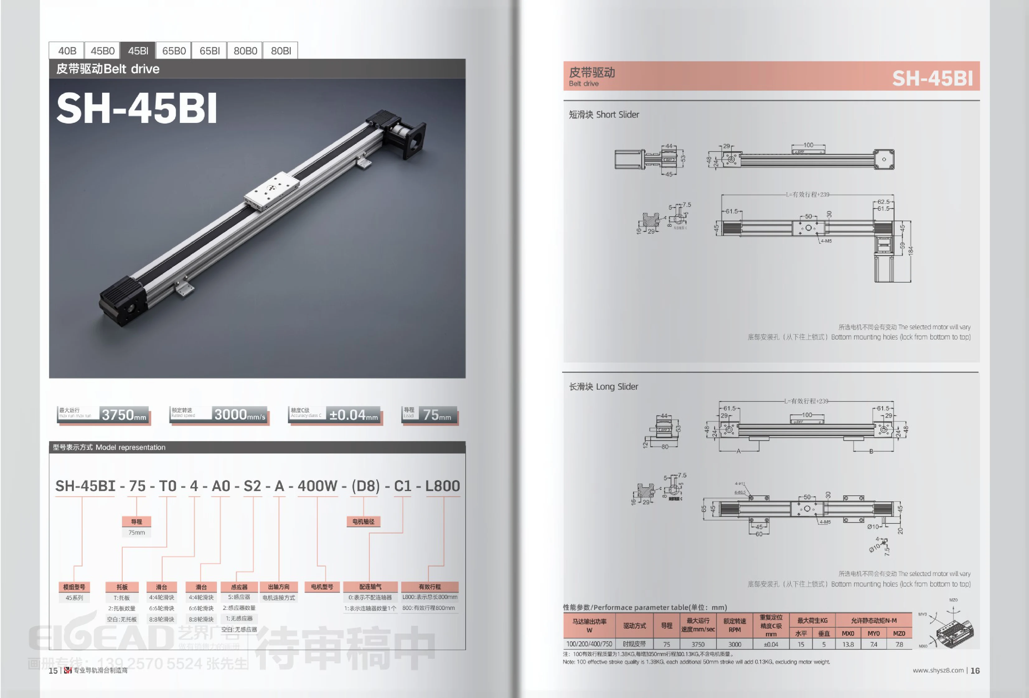
The SH-45BI series is a 45-series belt-driven linear module using a timing belt drive. It has a 75mm lead, a maximum operating speed of 3750mm/sec, a rated speed of 3000RPM, Class C repeat positioning accuracy of ±0.04mm, a maximum load capacity of 15kg, and an allowable static torque of 5/13.8N·m. It is compatible with 100/200/400/750W motors. The model code allows configuration of the carriage plate, 4/6/8-wheel slider, sensors and their quantity, motor power, motor shaft diameter, number of couplings, and effective stroke L, among other options. The module weighs approximately 1.38kg at a 100mm effective stroke, with approximately 0.13kg added for each additional 50mm of stroke, excluding the motor.
SH-65B0 Series Belt-Driven Linear Modules
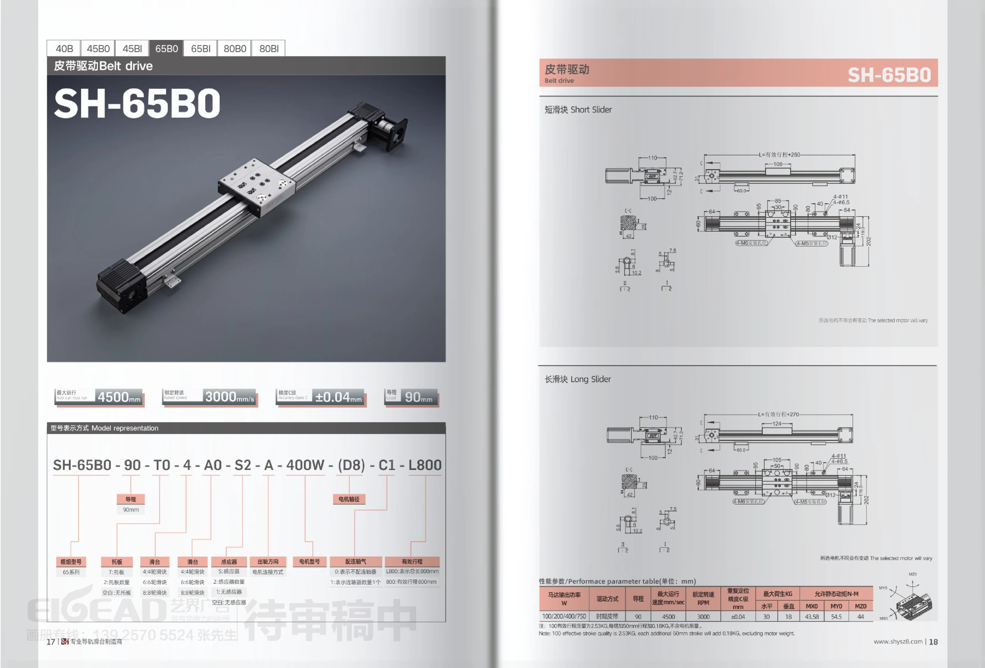
The SH-65B0 is a 65-series belt-driven (timing belt) linear module with an aluminum extrusion body and an internal timing belt drive. It has a standard lead of 90mm and can be fitted with a 100W, 200W, 400W, or 750W servo or stepper motor. Maximum operating speed is 4500mm/s, rated speed is 3000RPM, and C-grade repeatability is ±0.04mm. Maximum load is approximately 30kg, and allowable static torque is approximately 43.58~54.5N·m. Carriages are available with 4, 6, or 8 wheels. The mounting plate, number of sensors, output shaft direction (motor connection method), motor shaft diameter, number of couplings, and effective stroke L can be combined as specified in the model designation. Weight is approximately 2.53kg for a 100mm effective stroke, with an additional 0.18kg for each 50mm increase in stroke (excluding the motor). It is suitable for factory automation applications such as long-stroke, high-speed material handling, dispensing, loading and unloading, and inspection.
SH-65BI Series Belt-Driven Linear Modules
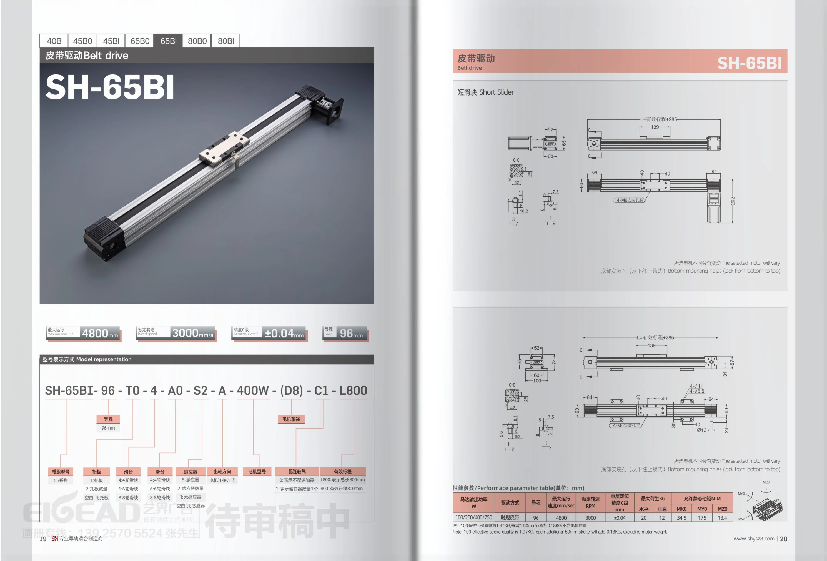
The SH-65BI is a 65-series belt-driven linear module with a timing belt drive, a 96mm lead, a maximum speed of 4800mm/s, a rated speed of 3000rpm, repeat positioning accuracy of ±0.04mm, and a maximum load of 20kg. Motor options include 100/200/400/750W. Ordering codes allow combinations of mounting plate, carriage roller count, sensors, output shaft direction, coupling, accessories, and stroke. Its short carriage and bottom mounting holes, fastened from below, make it suitable for automated handling, positioning, and similar applications. Weight at a 100mm effective stroke is approximately 1.97kg, increasing by approximately 0.18kg for every additional 50mm of stroke (excluding the motor).
SH-80B0 Belt-Driven Linear Module
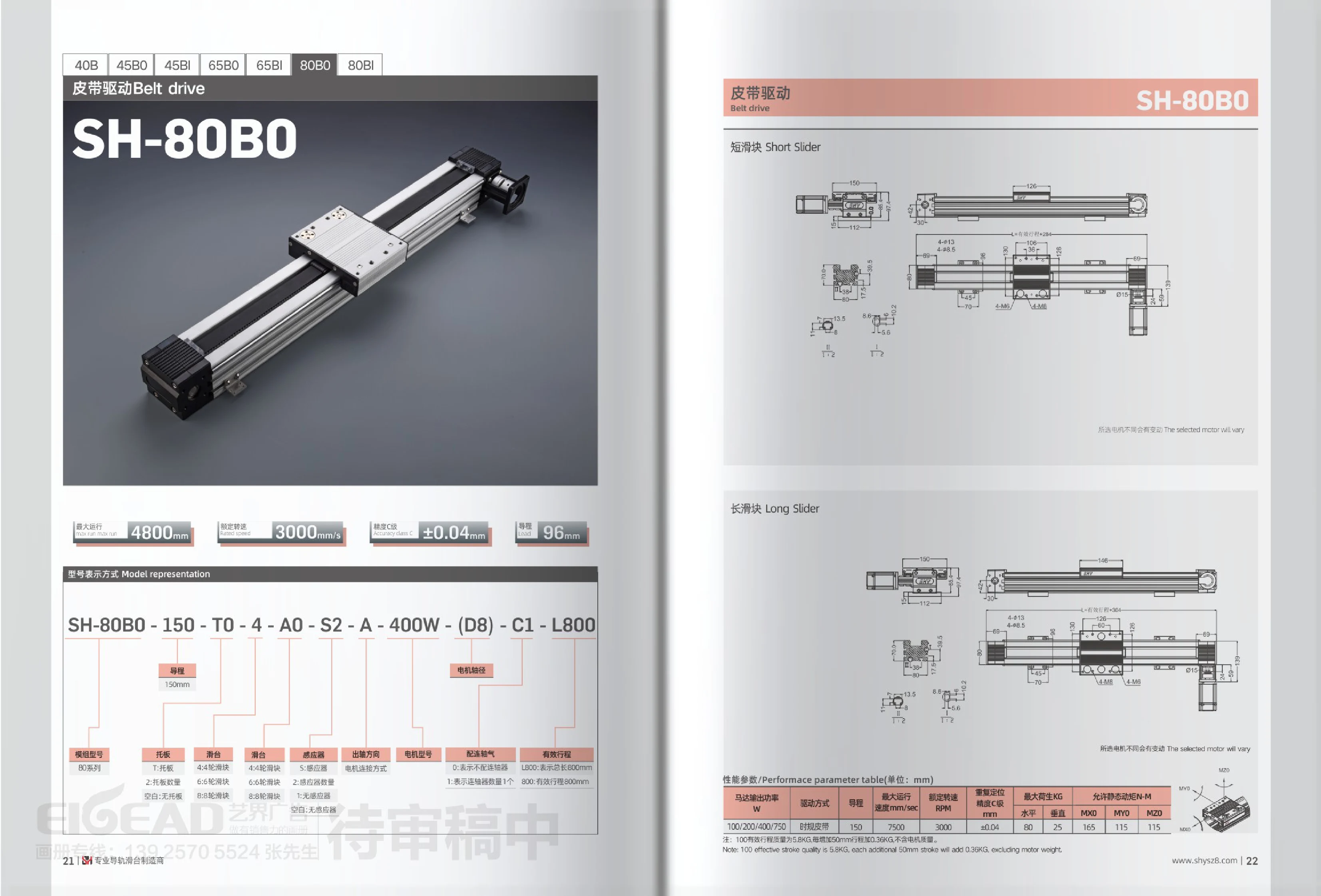
The SH-80B0 is an 80-series timing belt-driven linear module designed for medium- to long-stroke, high-speed handling and positioning applications. It has a standard lead of 150mm, a maximum operating speed of 7500mm/s, a rated speed of 3000RPM, C-grade repeat positioning accuracy of ±0.04mm, and a maximum load of 80kg. Motor options include 100W/200W/400W/750W, and the carriage is available with 4/6/8 wheels. Sensors, support plates, couplings, output shaft direction, and effective stroke are selected according to the model code. The module weighs approximately 5.8kg with a 100mm effective stroke, with approximately 0.36kg added for each additional 50mm of stroke (excluding the motor).
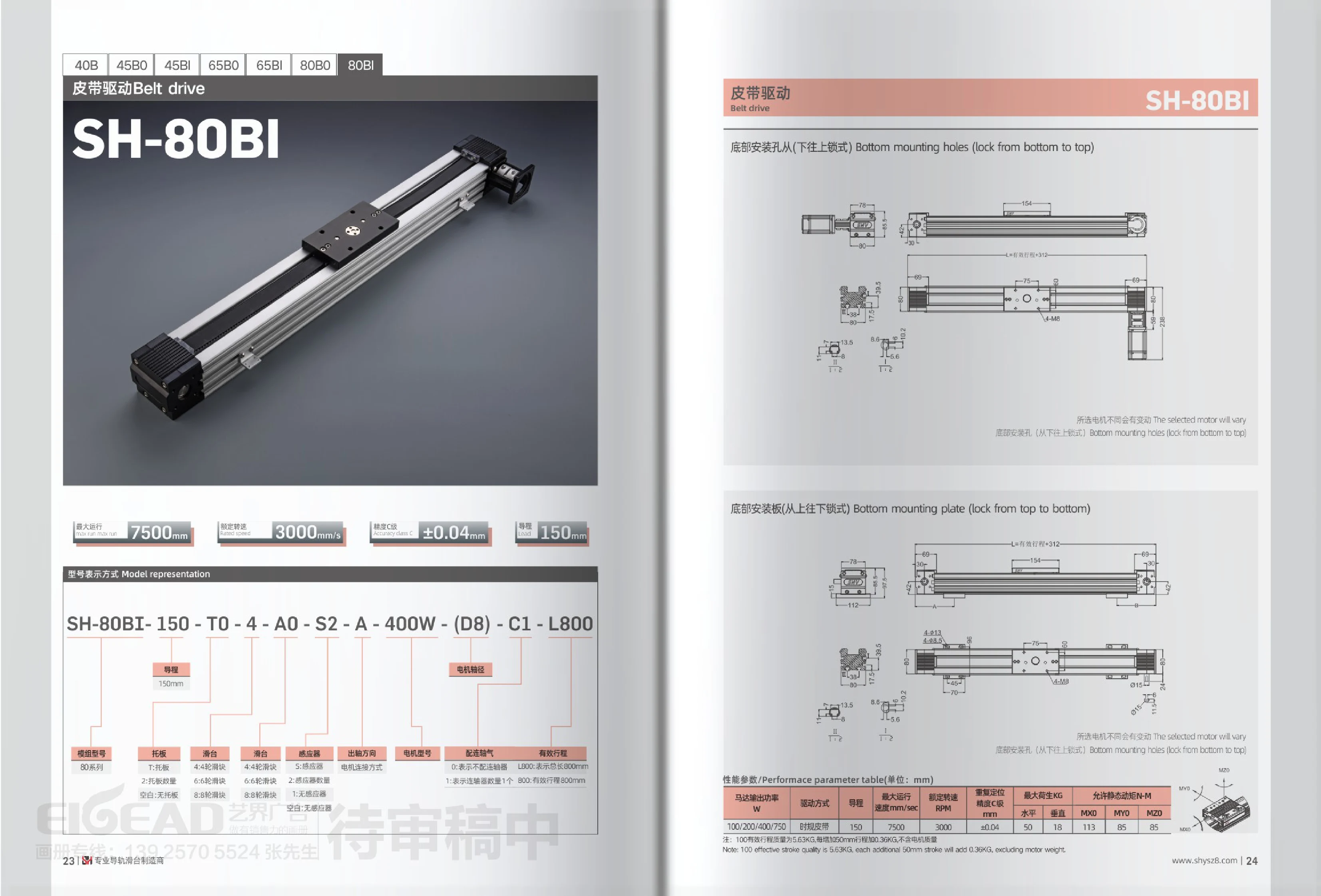
SH-80BI Series Belt-Driven Linear Modules
The SH-80BI series consists of timing belt-driven linear modules built with 80-series aluminum profiles. The carriage is available with 4-wheel, 6-wheel, or 8-wheel sliders, making it suitable for long-stroke, high-speed handling and positioning applications. It has a lead of 150mm, a maximum operating speed of 7500mm/s, a rated speed of 3000rpm, and repeatability of ±0.04mm. The allowable static torque is 18N·m for 50 teeth and 85N·m for 113 teeth. It is compatible with servo or stepper motors rated at 100W, 200W, 400W, or 750W. The quantities of carriage plates, sensors, and couplings can be configured as needed. The effective stroke is indicated by L followed by a number (for example, L800 means an effective stroke of 800mm). The module weighs 5.63kg with a 100mm effective stroke, with an additional 0.36kg for every 50mm increase in stroke (excluding the motor). Two mounting options are supported: bottom mounting holes, fastened from below, and bottom mounting plates, fastened from above.
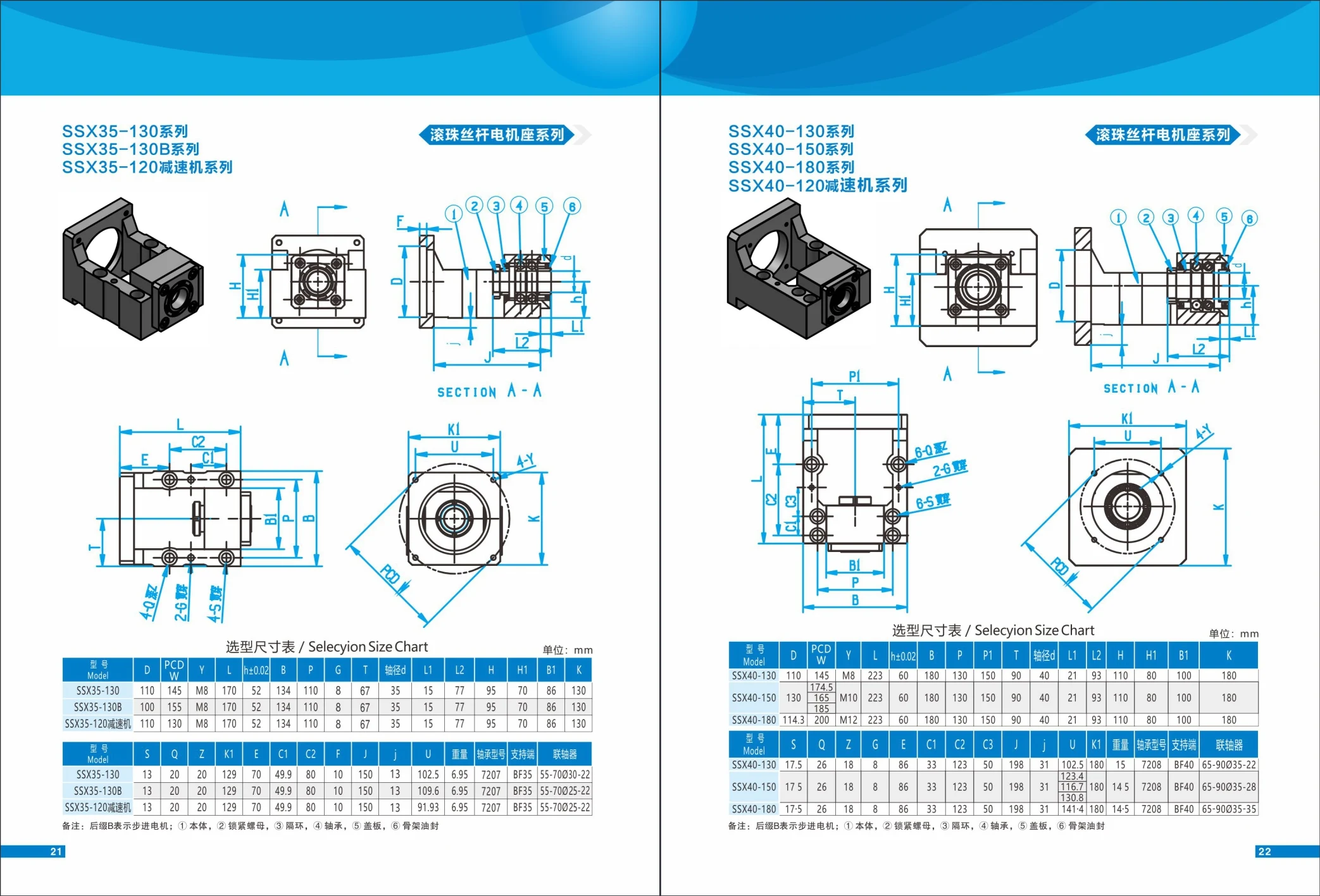
SSX35-130 Series
The SSX35-130 series is a lead-screw-driven linear module with a 35 mm shaft diameter, designed for precise positioning in automation equipment. The series includes a standard model (SSX35-130), a stepper motor model (SSX35-130B, where the suffix B indicates a stepper motor), and a reducer model (SSX35-120 reducer). Key dimensions: overall length 170 mm, width options of 110 mm and 100 mm, height 70 mm, and weight approximately 6.95 kg. It uses a 7207 bearing, a BF35 support end, and a 55-70030-22 or 55-70025-22 coupling. The assembly consists of ① the body, ② a locknut, ③ a spacer ring, ④ a bearing, ⑤ a cover plate, and ⑥ a frame oil seal, among other components. It is suitable for a wide range of automation applications, including precision positioning, conveying, and handling.
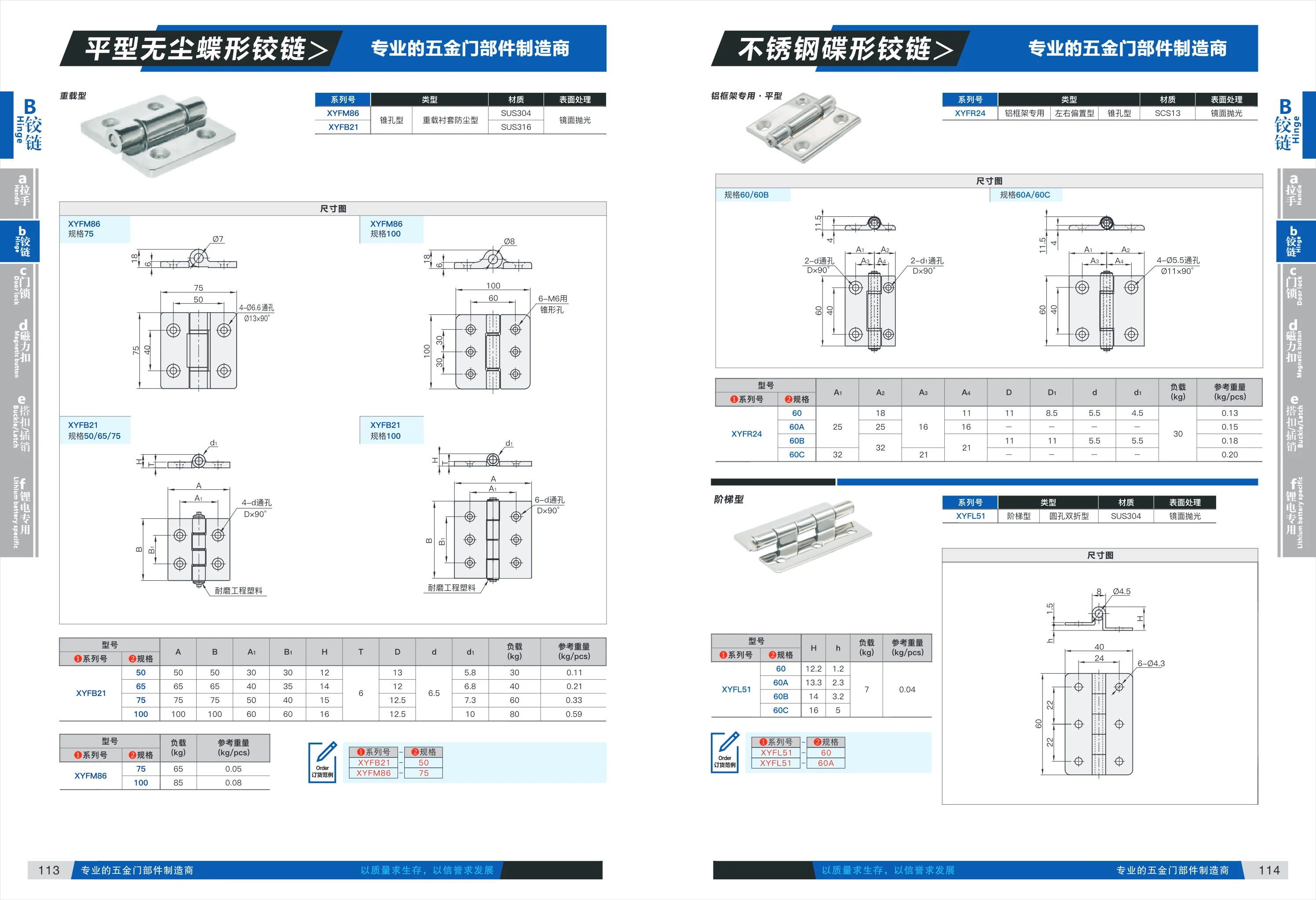
XYFM86 Series
The XYFM86 Series is a linear motion component for industrial automation, available in two load ratings: 75 kg (reference weight: 65 kg) and 100 kg (reference weight: 85 kg). It is suitable for applications requiring high-precision linear motion, such as automation equipment and robotics. Its compact design and high load capacity meet a range of application needs.
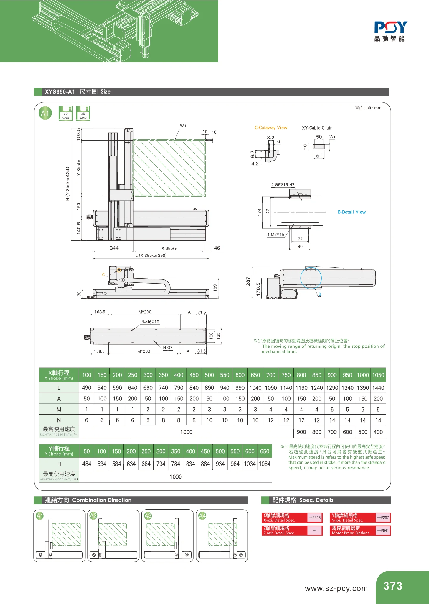
XYS650 Series Linear Modules
The XYS650 series linear module, base model XYS650-A1, is a linear motion unit for factory automation. X-axis travel ranges from 100~1050 mm in 50 mm increments, with a corresponding overall length L of 490~1440 mm. The maximum operating speed is 1000 mm/s. Depending on the stroke, the mounting and overall dimension parameters are A: 50~1000 mm, M: 1~3, and N: 6~8. It is suitable for medium- to long-stroke, high-speed handling and positioning applications. When selecting a model, check the L, A, M, and N dimensions against the stroke.
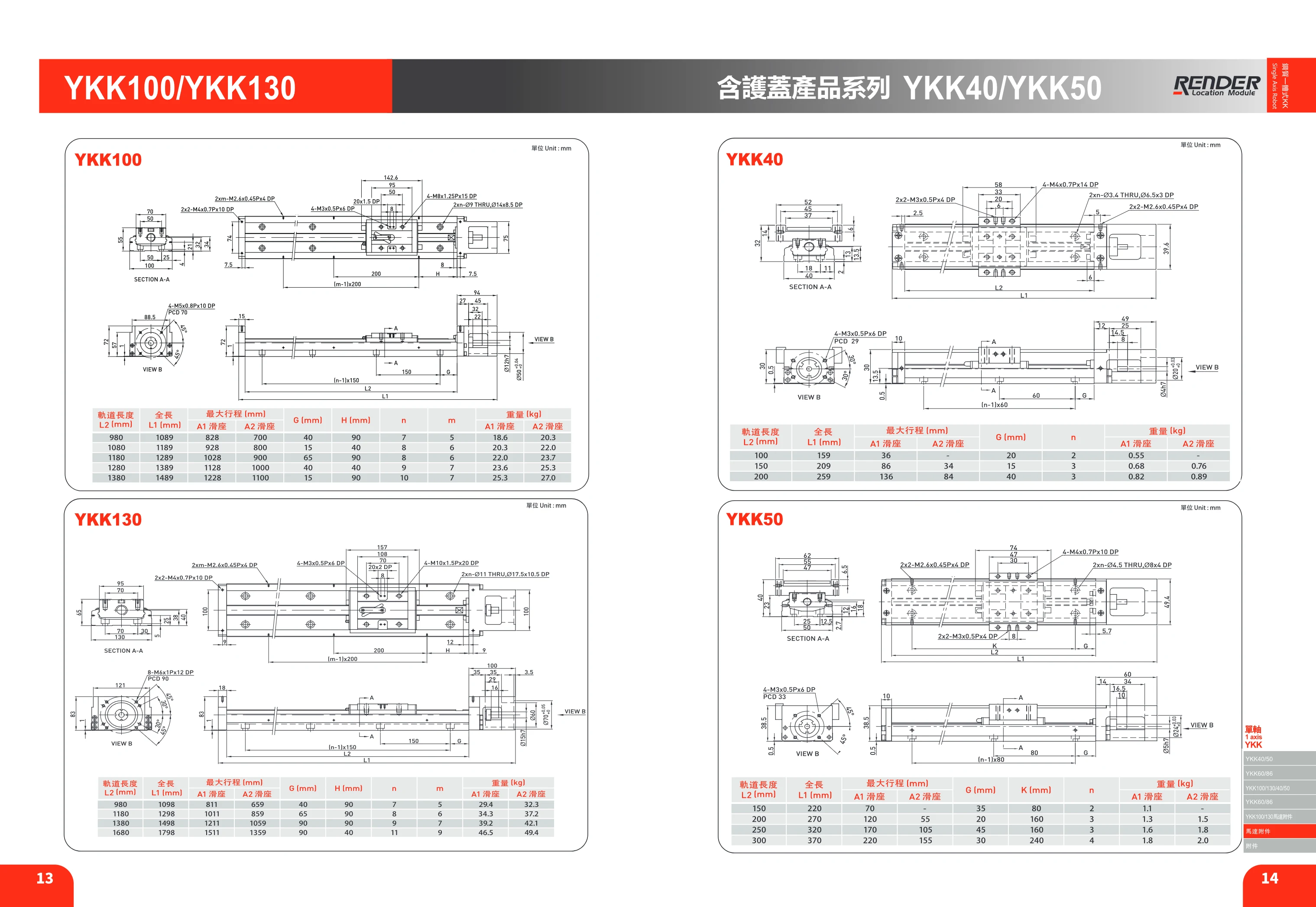
YKK40 Series Linear Modules
The YKK40 series comprises linear modules (linear slides) with extruded aluminum bodies. The catalog uses carriage configuration, rail length and overall length as the main selection criteria. The series offers A1 (single-carriage) and A2 (dual-carriage) configurations to suit different load and travel requirements. The catalog also specifies carriage spacing G (mm) and number of carriages n as mounting and selection parameters, along with rail length L2 and overall length L1 (both in mm). These dimensions help determine the travel and mounting clearance at both ends within a limited installation space. When selecting a module, confirm the carriage configuration (A1/A2), rail length L2 or overall length L1, required effective travel, drive method and mounting orientation. Effective travel is generally shorter than the rail length, as the carriage length and clearance for the end limits must be deducted. This page provides dimensional information; refer to other pages for the series to confirm specific travel specifications, load capacities and accuracy grades.