Hydraulic Components

030 Series Hydraulic Swing Clamp Cylinders
This series of 030 hydraulic swing clamp cylinders features carbon steel bodies treated by carbonitriding for a hard, wear-resistant surface. No mounting holes need to be prepared in advance; the cylinders bolt directly to the worktable and are suitable for clamping thicker workpieces. Two types are available: single-acting models use a spring for retraction, providing a simple system, while double-acting models use hydraulic circuits to control clamping and release. The swing direction can be left or right. The standard swing angle is 90°, with custom angles of 30°, 45° and 60° available. Bore diameters range from Φ14 to Φ45, vertical strokes from 8 to 14 mm, and total strokes from 16.5 to 27.9 mm. Theoretical clamping force at 250 kg/cm² ranges from 180 to 1,960 kg. The operating pressure range is 35–250 kg/cm², and standard hydraulic oil is used. Models include 030LS/RS/LD/RD-22/52/92/121/202 to suit a range of fixture applications.

040 Series Swing Clamp Cylinder
The 040 Series swing clamp cylinder features an externally threaded barrel for direct mounting on fixture plates. It is available in single-acting (spring return) and double-acting (hydraulic control for clamping and release) versions. Choose a right-hand (R) or left-hand (L) swing direction. Bore sizes range from Φ14 to Φ45 mm, vertical stroke from 8 to 14 mm, and total stroke from 16.5 to 27.9 mm. Theoretical clamping force is 180–1,960 kg at 250 kg/cm². The operating pressure range is 35–250 kg/cm². The standard swing angle is 90°; custom angles of 30°, 45°, and 60° are also available. The barrel is made of rotary steel and treated with carbonitriding for a hard, wear-resistant surface. Ideal for rapid clamping and release in a wide range of fixtures.

050 Series Hydraulic Swing Clamp Cylinder
The 050 Series Hydraulic Swing Clamp Cylinder has a very low mounting height, making it suitable for applications with limited space. Its main body can be recessed below the worktable surface. Installation is simple and requires only three or four bolts. It is available in single-acting and double-acting versions. The single-acting version has a simple internal system with no unloading circuit and uses a spring for return; it can return without a load. On the double-acting version, clamping and release are controlled entirely by the hydraulic circuit, with the process controlled by switching the direction of the directional control valve. The cylinder body is made of carbon steel and treated by carbonitriding for high surface hardness and good wear resistance. The cylinder bore ranges from Φ14 to Φ45 mm, the vertical stroke from 8.1 to 14.0 mm, and the total stroke from 16.5 to 27.9 mm. The theoretical clamping force at 250 kg/cm² ranges from 173 to 1,830 kg. The operating pressure range is 35–250 kg/cm². The standard swing angle is 90°, with 30°, 45°, and 60° angles available on request. The 050 Series offers right-hand (R) and left-hand (L) rotation, single-acting (S) and double-acting (D) operation, and model sizes 22, 52, 92, 121, and 202.

HSL Hydraulic Swing Clamp Cylinder
The HSL series hydraulic swing clamp cylinder is suitable for dedicated machines and MC fixtures used in parts manufacturing, and can greatly improve production efficiency. During operation, the piston first moves downward while the clamping arm swings to the designed angle, then continues in a straight line to clamp the workpiece. The cylinder body is made of carbon steel for machine casting. Its inner wall is specially machined to a smooth finish for a long service life. Installing a flow control valve is recommended to prevent excessive speed. Do not clamp a workpiece during the swing stroke. If you need to extend the clamping arm, do not exceed 1.5 times its original length. A variety of mounting styles are available, including standard, MF, FA, TB, FAM, and FCM types. Bore diameters range from 25 to 63 mm, with stroke options including 24.5, 29.5, 33, 44.5, and 50 mm. Compact and reliable, this series is an ideal choice for automated clamping stations.

HSP-AH Series Air-Hydraulic Dual-Purpose Support Cylinder

ISO-PHS Rod End Joint
The ISO-PHS rod end joint is a spherical connecting accessory used at the end of a pneumatic or hydraulic cylinder piston rod. Its spherical bearing compensates for installation misalignment, allowing the cylinder to pivot through a limited angle during reciprocating motion. The catalog provides selection dimensions for bore sizes of 32, 40, 50, 63, 80, 100, 125, 160, and 200 mm, including PA, PB, PC, PD, PE, and PF dimensions and PG thread specifications (M10×1.25 to M36×2.0). PH is the associated height dimension. It is suitable for MOB and other hydraulic cylinders and actuators with ISO mounting interfaces. Select the joint to match the piston rod thread and cylinder bore.

HNFS Series High-Pressure Swing Clamp Cylinder
As the piston rod retracts, the clamp arm rotates; after clamping, the piston rod continues to retract linearly. Clockwise or counterclockwise rotation is available. The standard angle is 90°, with 30°, 45°, and 60° also available. The cylinder body is made of high-grade aluminum with a hardened surface.
HNSD Series Flanged Double Pipe
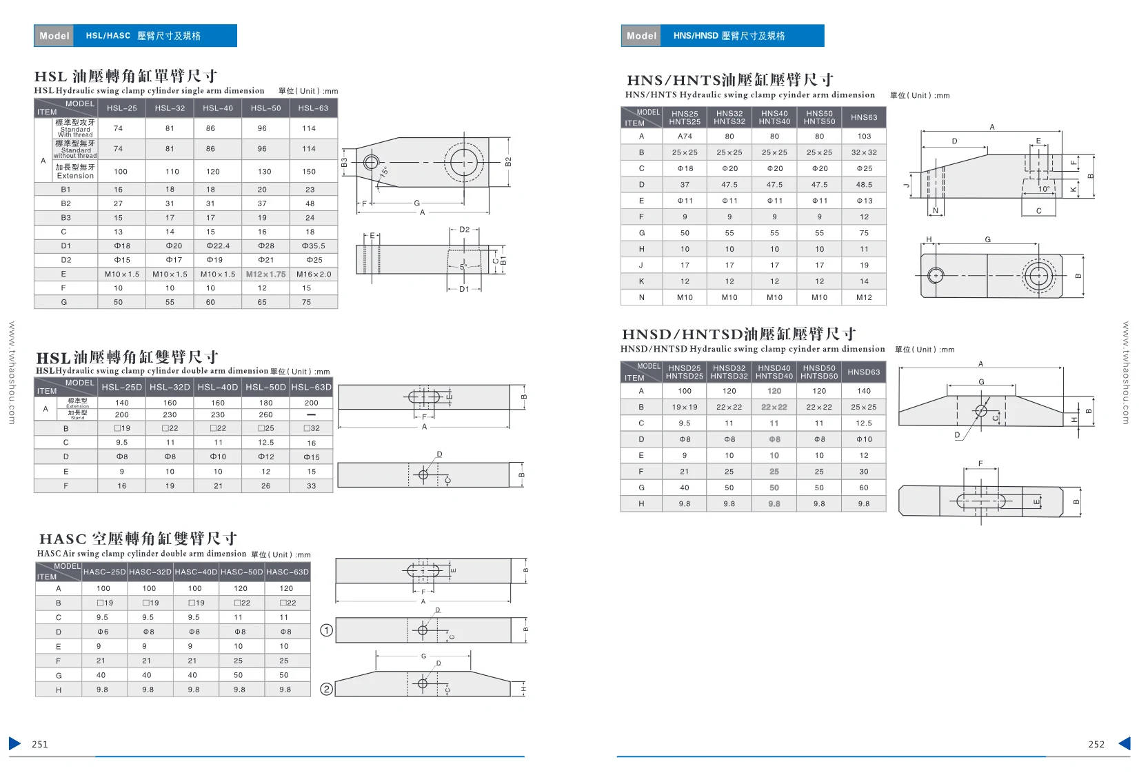
HNS/HNTS Series Swing Clamp Cylinders
The HNS/HNTS series hydraulic cylinder clamping arms (swing clamps) are hydraulically driven swing-clamping units commonly used in automated clamping fixtures. Available bore sizes are 25, 32, 40, 50, and 63 mm, with single-arm and double-arm configurations. For a detailed list of mounting dimensions, see the catalog. Suitable for a wide range of hydraulic clamping systems.

HCT Series Top-Flange High-Speed Hydraulic Swing Clamp (Single-Acting)
The title indicates single-acting. The page diagram shows the direction of rotation and the clamped and released positions.

YX Series Support Cylinder Retractable Base
This cylinder features a compact structure and rational design. Its retractable base accommodates workpieces of varying thickness and prevents interference while the support cylinder is operating.
HL5H Series Tie-Rod Hydraulic Cylinders
The page lists two configurations: pipe-connected and G manifold-mounted.

JR Series Rotary Joint

HRPV Series Hydraulic Pressure Reducing Valve
The page title is “HRPV Hydraulic Pressure Reducing Valve”; the circuit diagram labels the pressure source, pressure control valve, and safety valve.
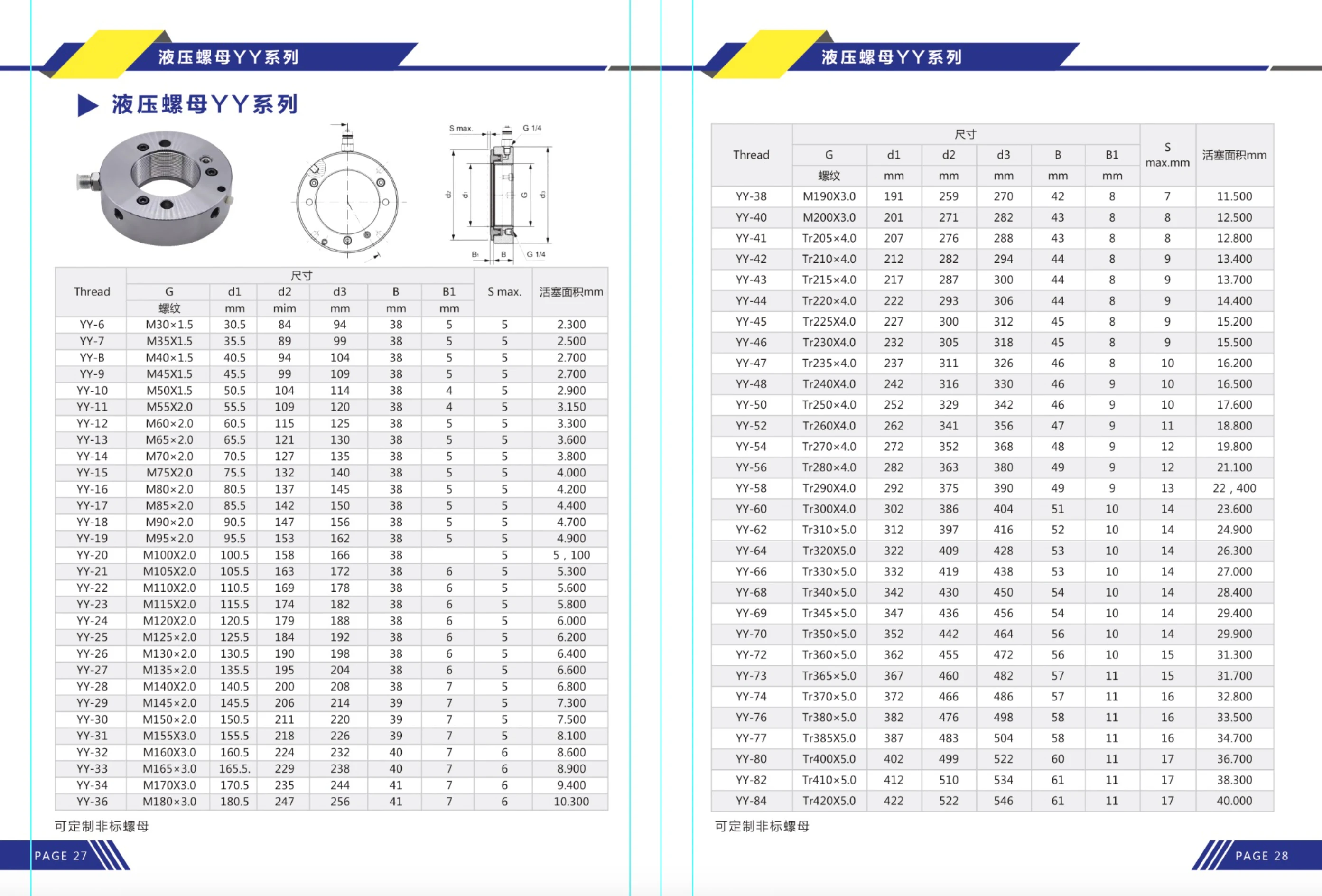
YY Series Pistons
The YY series pistons feature metric (M) or trapezoidal (Tr) threaded connections and are designed for piston assemblies in hydraulic or pneumatic cylinders. A range of sizes is available, with G thread sizes from M190×3.0 to Tr420×5.0, d1 diameters from 259 to 522 mm, and maximum strokes (S max) from 11.5 to 40 mm. These high-precision products are suitable for heavy-duty and high-pressure applications.
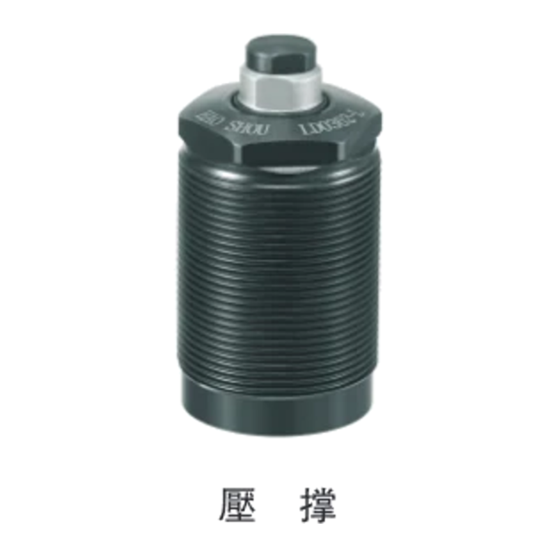
LD Series Hydraulic Support Cylinder
LD series hydraulic support cylinders feature a sleeve and tapered-piston design that delivers powerful support. In machining applications, they reduce vibration, prevent deformation, and absorb cutting forces to improve machining accuracy. Their compact construction ensures stable performance and a long service life. The small bolt-mounted design is suitable for installation in the limited space available on fixtures and supports workpieces with uneven surfaces. The model code is formatted as LD[body code]-[spring force][-option]. The four body codes are 0262 (M26x1.5), 0302 (M30x1.5), 0362 (M36x1.5), and 0452 (M45x1.5). Spring-force options are L (light spring) and H (heavy spring). Options are no suffix (hydraulic-rise type/standard) and E (spring-rise type). Key specifications: support force 3.0–10.0 kN (at 7 MPa hydraulic pressure), plunger stroke 6.5–10 mm, maximum operating pressure 7.0 MPa, minimum operating pressure 2.5 MPa, proof pressure 10.5 MPa, and operating temperature 0–70°C. Cylinder capacity is available in standard and E types; weight ranges from 0.20 to 0.75 kg. The design includes a contact bolt. Ensure that the support force is at least 1.5 times the clamping force.
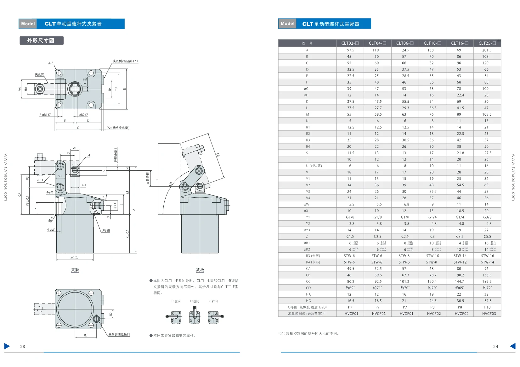
CLT Single-Acting Linkage Clamp
The CLT series single-acting linkage clamp is a spring-return, hydraulically actuated clamping device designed for quickly securing workpieces in fixtures. Its compact linkage mechanism delivers stable clamping force in confined spaces. The series includes six sizes, from CLT02 to CLT25, with a range of mounting dimensions and G-thread oil port connections. The clamp body is made of high-strength steel for a long service life. Typical applications include machining centers, welding fixtures, and automated production lines. The operating oil pressure range is 1–7 MPa, the operating temperature range is 0–70°C, and the fluid is standard mineral-oil-based hydraulic oil.

CVH Centering Vise
Hydraulic centering vise with two jaws that move the same distance to keep the workpiece center constant. Designed for machining centers, it eliminates the need to machine unhardened jaws to shape. Operating oil pressure: 1–7 MPa; guaranteed pressure resistance: 10.5 MPa; ambient operating temperature: 0–70°C. Use standard mineral-oil-based hydraulic fluid (equivalent to ISO VG 32). Available in three sizes: CVH04 (4 in), CVH06 (6 in), and CVH08 (8 in), with clamping forces of 10, 20, and 30 kN, respectively, at 7 MPa. Jaw strokes are 5.6, 5.8, and 6.0 mm, respectively; maximum external clamping diameters are 100, 145, and 190 mm; maximum internal clamping diameters are 125, 170, and 220 mm. Two piping options are available: pad piping (G) and RC-thread piping (S).
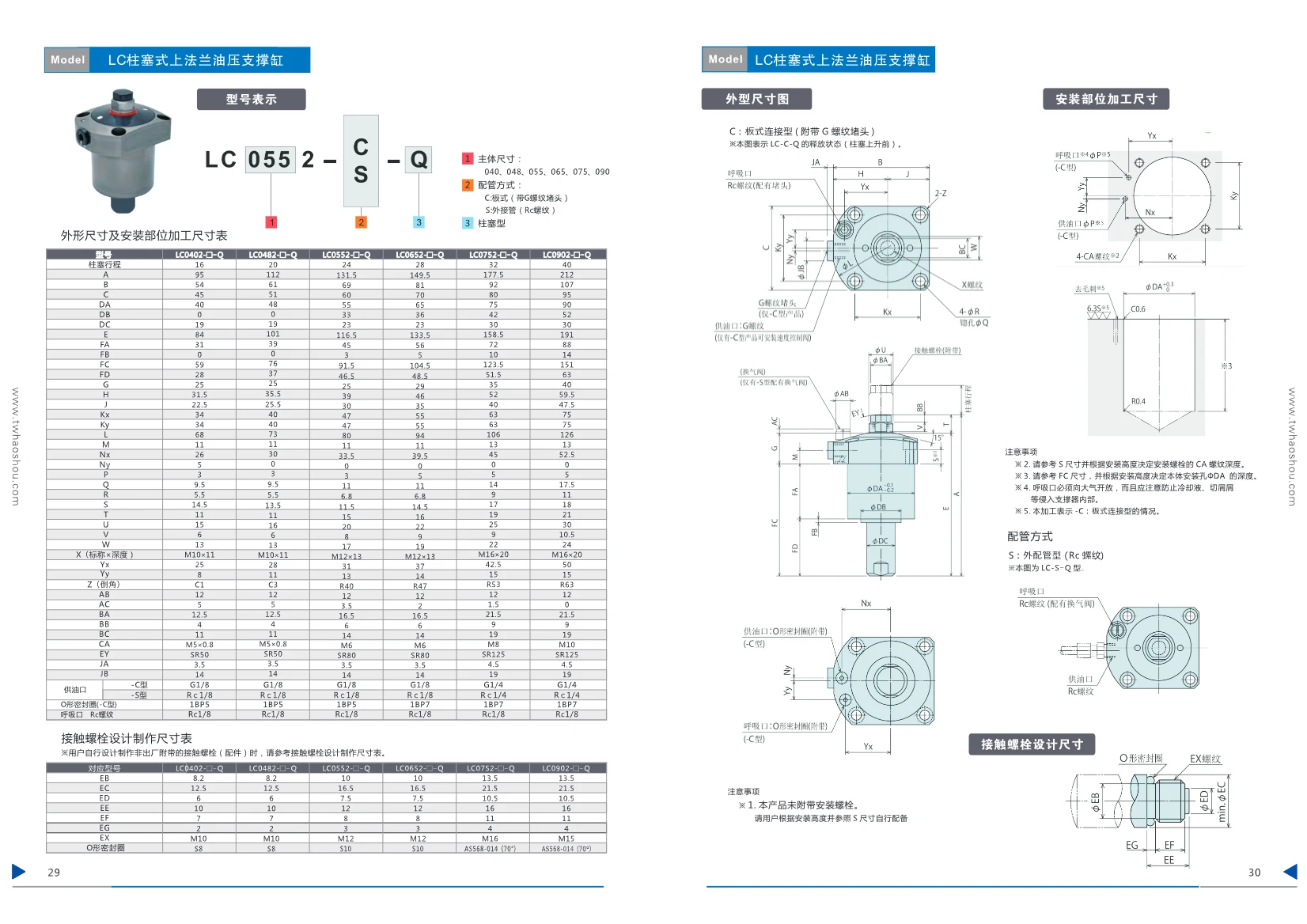
LC Plunger-Type Top-Flange Hydraulic Support Cylinder
The LC plunger-type top-flange hydraulic support cylinder is a hydraulically actuated support element used to hold workpieces during machining and prevent deformation and vibration. The series includes five sizes, with plunger strokes ranging from 16 mm to 32 mm, and offers two oil-port connection options: manifold-mounted (-C type) and threaded (-S type). It provides high load capacity and flexible installation, making it suitable for automated production lines and fixture systems. Key specifications include body dimensions, mounting-hole dimensions, and port threads; see the dimensional table for details.
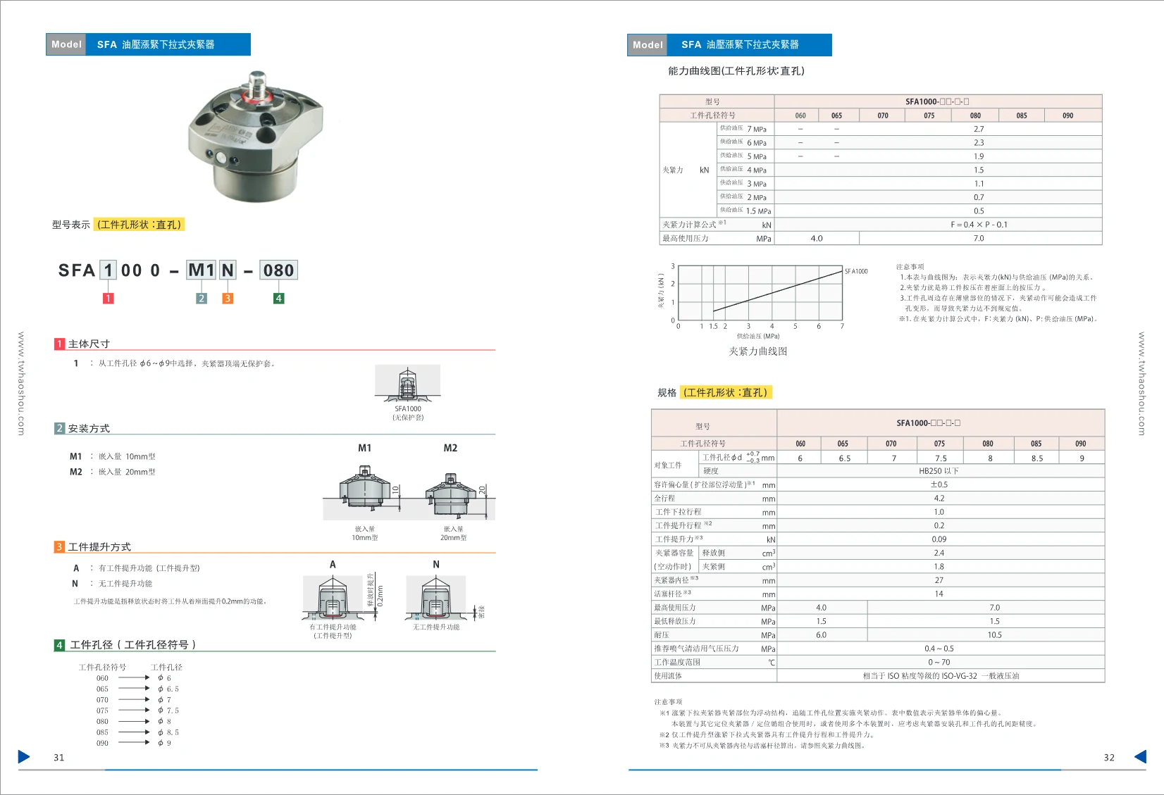
SFA Hydraulic Expanding Pull-Down Clamp
The SFA series hydraulic expanding pull-down clamp uses hydraulic pressure to pull the workpiece down and secure it against a reference surface. This series is designed for straight holes with workpiece hole diameters of φ6–φ9 mm and comes in a fixed body size of type 1000. Two mounting options are available: type M1 (embedment depth 10 mm) and type M2 (embedment depth 20 mm). Workpiece lift options are type A (with a workpiece-lifting function that raises the workpiece by 0.2 mm when released) and type N (without a lifting function). The workpiece-hole symbols correspond to the following actual diameters: 060 (φ6), 065 (φ6.5), 070 (φ7), 075 (φ7.5), 080 (φ8), 085 (φ8.5), and 090 (φ9). The maximum operating oil pressure is 7.0 MPa. Total stroke is 4.2 mm, operating downward stroke is 1.0 mm, and workpiece lift stroke is 0.2 mm. The operating fluid is ISO VG-32 hydraulic oil. The relationship between clamping force and oil pressure is given by the formula F = 0.4 × P − 0.1 (kN). For positioning, use in combination with a floating structure is recommended; the allowable eccentricity is ±0.5 mm. Operating temperature range: 0–70°C.

CLM Rod-In Clamp
The CLM series rod-in clamp (also known as a rod-entry clamp) is available with various detection options, including built-in air-lock and built-in helium leak detection. It comes in five sizes: 04, 05, 06, 10, and 16. The clamp arm can be oriented to the left (L), forward (F), or right (R). Detection options include Type T (3-point detection) and Type C (clamp detection). Hydraulically driven and rated for an operating pressure of 7 MPa, the clamp has G1/8 or G1/4 oil ports. Its compact design makes it suitable for workpiece positioning and clamping, and it is widely used in automated production lines and fixture systems.

CGC Hydraulic Expansion Clamp
The CGC series hydraulic expansion clamp is a hydraulic fixture for locating and clamping workpieces by their internal bores. It operates at a pressure of 7 MPa. Hydraulic force expands the sleeve to clamp the bore, making the clamp suitable for precision machining and automated production lines. A range of specifications is available, including 2-jaw and 3-jaw versions, to accommodate different bore diameters. During installation, ensure the surface roughness is R6.3 or finer and apply an appropriate amount of grease. The dimensional drawings provide detailed mounting-hole dimensions for models 12 through 16 to ensure interchangeability and accurate installation. The clamp uses fluororubber seals with a hardness of H≤90; the seating surface has a hardness of HRC 55, ensuring stable clamping over the long term.

FP Ball-Locking Pull-Down Cylinder
The FP series comprises hydraulic ball-locking pull-down cylinders with a low-pressure (1–7 MPa), single-acting design. A ball-locking mechanism enables quick workpiece clamping and release. Five body sizes are available, with outside diameters of 39, 55, 65, 75, and 90 mm. Total stroke ranges from 6.7 to 12 mm, and clamping stroke from 3.8 to 8.7 mm. Choose between a manifold-mounted connection (G) and external piping (S); a coolant outlet (D) can also be added. These cylinders are suitable for applications requiring secure clamping, such as automated production lines and workholding fixtures. Their compact, lightweight design features spring return, high tolerance for eccentric loading, and stable performance.
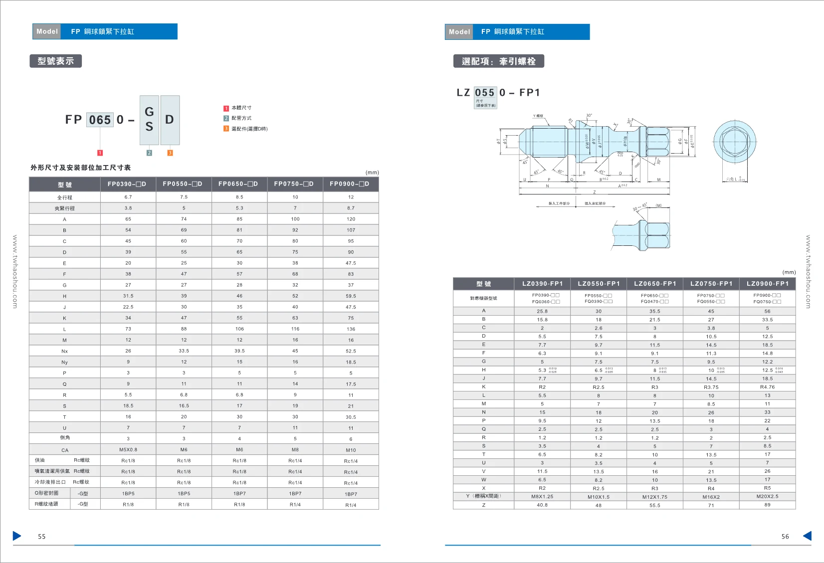
LZ Steel-Ball Locking Pull-Down Cylinder
This series of steel-ball locking pull-down cylinders includes FP-series main units and LZ-series pull-stud accessories. The FP series is available in several sizes (0390, 0550, 0650, 0750, and 0900), with different strokes and mounting dimensions. The optional LZ-series pull studs are designed for use with FP-series units and provide precise bolt connection dimensions for automated clamping applications. A steel-ball locking mechanism ensures reliable clamping.

CST Hollow Workpiece Supports
This series of hydraulically actuated hollow workpiece supports holds workpieces during machining to prevent deformation. The hollow design allows components or clamping mechanisms to pass through. Support force ranges from 4 to 20 kN (at 7 MPa), with an operating oil pressure of 2.5–7 MPa, a guaranteed pressure resistance of 10.5 MPa, and an operating temperature of 0–70°C. Available in five sizes: 04, 06, 10, 16, and 25. Designed for automated fixture systems and use with clamps.
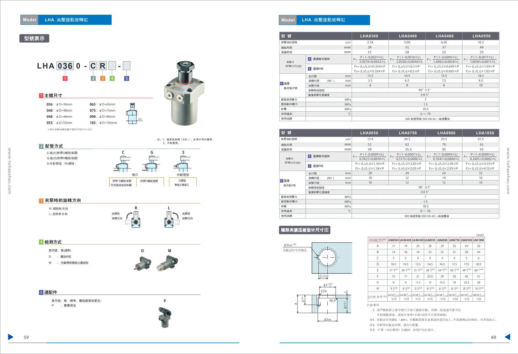
LHA Series Hydraulic Double-Acting Rotary Cylinder
The LHA Series Hydraulic Double-Acting Rotary Cylinder is an industrial automation component that uses hydraulic power to perform rotary and linear clamping actions. It is available in multiple body sizes (outer diameter 36~105mm) and supports plate piping (C/G type) and external piping (S type). The rotation direction can be selected as clockwise (R) or counterclockwise (L). Detection options include the standard type, double-rod type (D), and air sensor plate connection type (M). The optional accessory is the dual clamping arm type (P). The cylinder bore ranges from 31~44mm (for some models), and the piston rod diameter is 15~25mm; the clamping force calculation formula varies by model. Total stroke is 13.5~32mm, comprising a 90° rotation stroke of 5.5~16mm and a clamping stroke of 8~16mm. Weight is 0.7~10.1kg. The speed control valve must be purchased separately; the clamping arm, pin, and retaining ring are not included. The ordering code is LHA[body size]0-[piping method][rotation direction]-[detection method][optional accessory].

CTM Rotary Position-Sensing Clamp
The CTM series consists of rotary position-sensing clamps designed for hydraulic operation. The operating pressure range is 1.5–7 MPa, the proof pressure is 10.5 MPa, and the ambient operating temperature range is 0–70°C. They use mineral-oil-based hydraulic fluid (ISO VG 32) and can be used in environments where water-soluble cutting fluid is sprayed. The clamps rotate through 90° (±3°), with positioning-slot accuracy of ±1° and clamping repeatability of ±0.5°. Four sizes are available: CTM04, CTM05, CTM06, and CTM10. Cylinder force ranges from 3.5 to 9.4 kN, cylinder bore from 31 to 51 mm, and piston rod diameter from 18 to 30 mm. Total stroke is 12–15.5 mm, rotation stroke is 6.5–10 mm, and clamping stroke is 5 mm. Multiple mounting options are available; see the drawings for overall dimensions.

CLU Link Clamp
The CLU series link clamps use a linkage mechanism to quickly clamp and release workpieces. Their compact design delivers high clamping force. Six sizes are available: 02, 04, 06, 10, 16, and 25. The clamping arm can be installed in a left-facing (L), front-facing (F), or right-facing (R) direction. Special versions include a double-ended rod (E) and a pressure sensor (A). The working fluid is hydraulic oil, and cylinder capacities range from 9.0 cm³ to 164.3 cm³. A variety of mounting and connection dimensions are available, along with multiple piping options. O-rings are included as standard. Pneumatic ports for confirming the clamped and released positions are available. These clamps are suitable for securing workpieces on automated production lines, machine tools, welding equipment, and other applications.
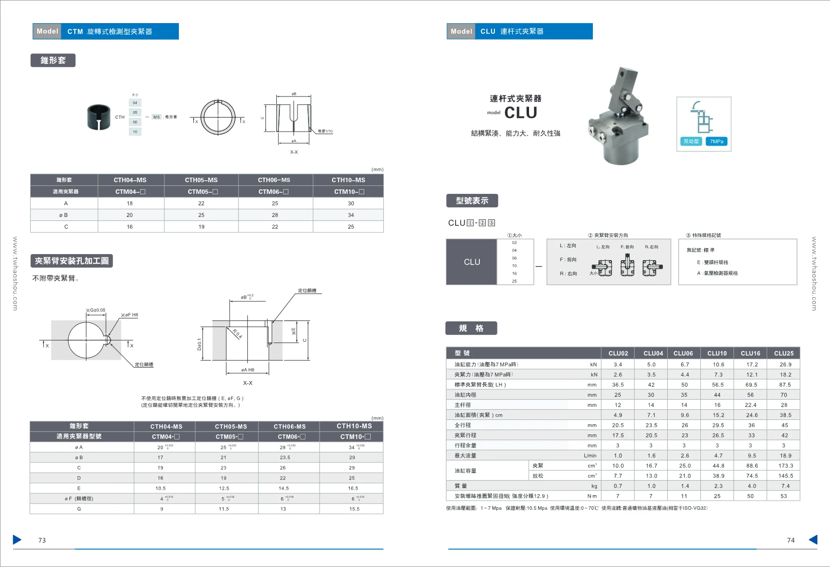
CTH Series Tapered Bushings
CTH Series tapered bushings are positioning accessories designed for CTM Series clamps. They ensure accurate installation and orientation of the clamp arm. The series is available in four sizes: CTH04-MS, CTH05-MS, CTH06-MS, and CTH10-MS, with bore diameters øA of 20 mm, 25 mm, 28 mm, and 34 mm, respectively. Used with the precision slot (øF) and locating pin, they allow the clamp arm to be positioned and installed quickly and easily. The clamp arm is not included, allowing users to choose the orientation to suit their needs. High dimensional accuracy ensures reliable clamp operation. These bushings are widely used in automated production lines, pneumatic fixtures, and similar applications.

LM/LJ Series Clamping Cylinders
The LM/LJ series clamping cylinders are designed for workpiece clamping applications. The body is available in aluminum alloy (LM series) or alloy steel (LJ series). Bore diameters range from 30 to 105 mm, total stroke from 16 to 49 mm, and clamping stroke from 14 to 46 mm. Maximum operating pressure is 7.0 MPa, minimum operating pressure is 2.5 MPa, proof pressure is 10.5 MPa, and the operating temperature range is 0–70°C. Three piping options are available: C (manifold mounting with G-thread plug), G (manifold mounting), and S (piping type with Rc thread). The clamp arm can be oriented left, center, or right, allowing a variety of configurations. Standard and extended clamp arm accessories are available. These cylinders are widely used in automated production lines, fixture systems, and more.
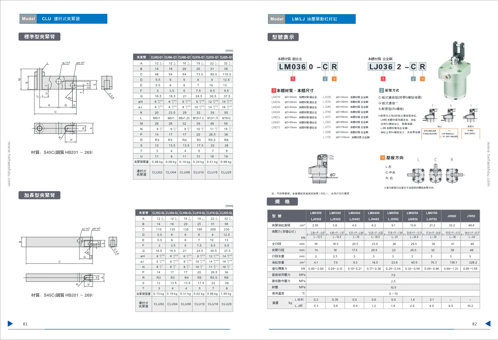
CLH Series Clamping Arms
The CLH series comprises hydraulically or pneumatically actuated clamping arms, available in standard (G1) and extended (GL) versions, along with compatible toggle-link clamps (CLU series) and clamps (CLW series). Made with an aluminum-alloy body, these arms are lightweight yet highly rigid, and are suitable for clamping and releasing workpieces in a wide range of fixture systems. The series covers six sizes from 02 to 25, with precise mounting dimensions and locating holes for stable clamping with various cylinder bodies. Every model offers high repeatability and a compact design. The clamping arm connects to the clamp through mounting holes for easy installation, making it suitable for automated production lines and fixture stations.

CLW High-Pressure Link-Type Clamp
The CLW series high-pressure link-type clamp features a compact design, high clamping force, and excellent durability. It is designed for clamping workpieces in hydraulic systems and is available in five sizes (04, 06, 10, 16, and 25) with three clamping-arm mounting orientations: left (L), forward (F), and right (R). The operating pressure range is 1–7 MPa, with a guaranteed pressure resistance of 10.5 MPa. The ambient operating temperature range is 0–70°C. Use standard mineral-oil-based hydraulic fluid. See the accompanying table for detailed dimensions. The clamp can be used with a pressure plate (LZ-LJ1).
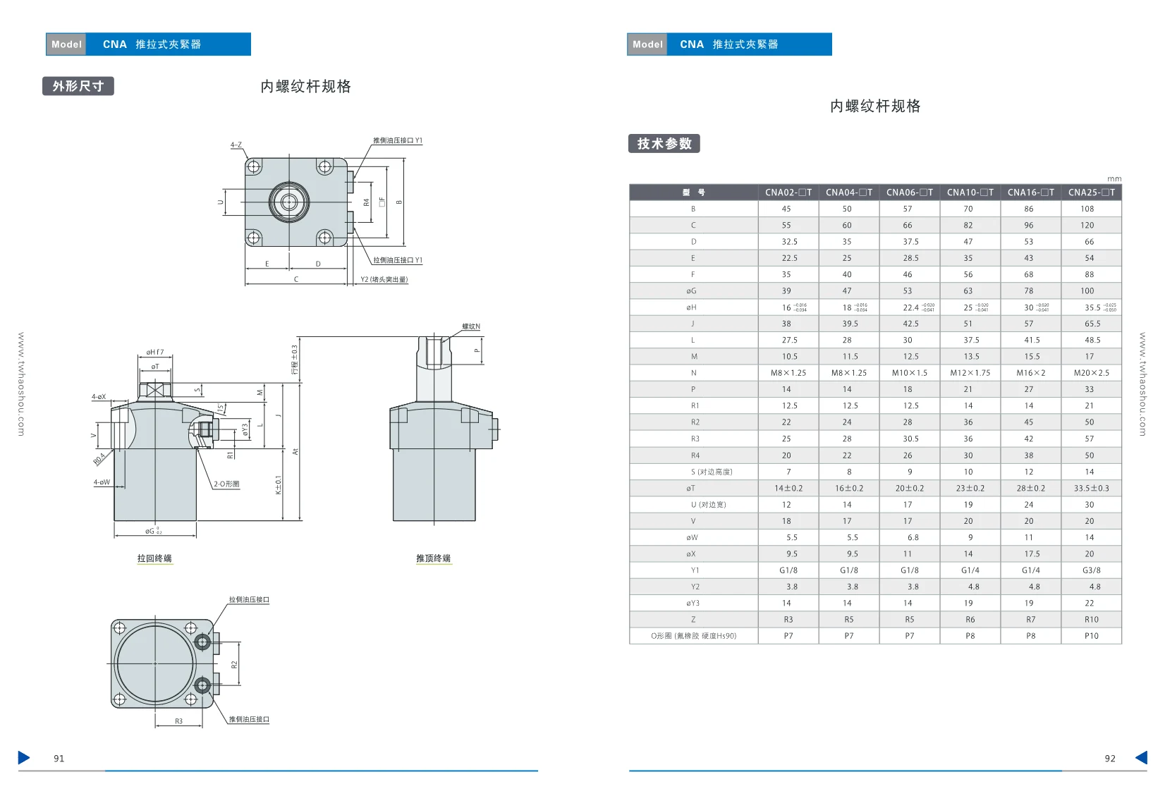
CNA Push-Pull Clamp
The CNA series push-pull clamp is a hydraulically actuated clamping element designed for applications such as die clamping and workpiece positioning. It is available with three rod-end configurations: internal-thread rod (T type), pin rod (P type), and external-thread rod (M type), in six sizes: CNA02, CNA04, CNA06, CNA10, CNA16, and CNA25. Stroke varies by size; for example, the CNA02 has a stroke of 10–100 mm (in selected increments), while the CNA25 has a stroke of 20–110 mm. The operating pressure range is 1.0–25.0 MPa, the proof pressure is 37.5 MPa, and the ambient operating temperature range is 0–70°C. The product uses fluororubber O-rings (hardness Hs90) and includes shims for adjustment. See the catalog for detailed specifications, including overall dimensions, cylinder capacity, and weight.

CMC Push-Pull Clamp
The CMC series push-pull clamps are hydraulically actuated and designed for industrial applications such as clamping and positioning. Models include CMC 01, CMC 03, CMC 04, CMC 06, CMC 10, and CMC 20, with strokes of 5 mm, 10 mm, 15 mm, 5 mm, 10 mm, and 15 mm, respectively. Cylinder force varies by size, ranging from 0.16 kN to 9.9 kN at 25.0 MPa. The operating pressure range is 1.0–25.0 MPa, the proof pressure is 37.5 MPa, and the ambient temperature range is 0–70°C. The plunger tip is available in two shapes: screw-type (standard) and ball-type. The compact design is easy to install and suitable for applications such as automated production lines and fixtures.

CMD Series Hydraulic Cylinders
CMD series miniature hydraulic cylinders feature a working stroke of 5–20 mm, piston area of 0.84–11.07 cm², maximum flow rate of 4.2–55.4 cm³/s, oil capacity of 0.5–4.6 cm³, and weight of 0.10–0.46 kg. The operating pressure range is 1.5–35 MPa, the proof pressure is 52.5 MPa, and the operating temperature range is 0–70°C. Multiple mounting options are available, making them suitable for a range of industrial applications, including clamping, positioning, and pushing.
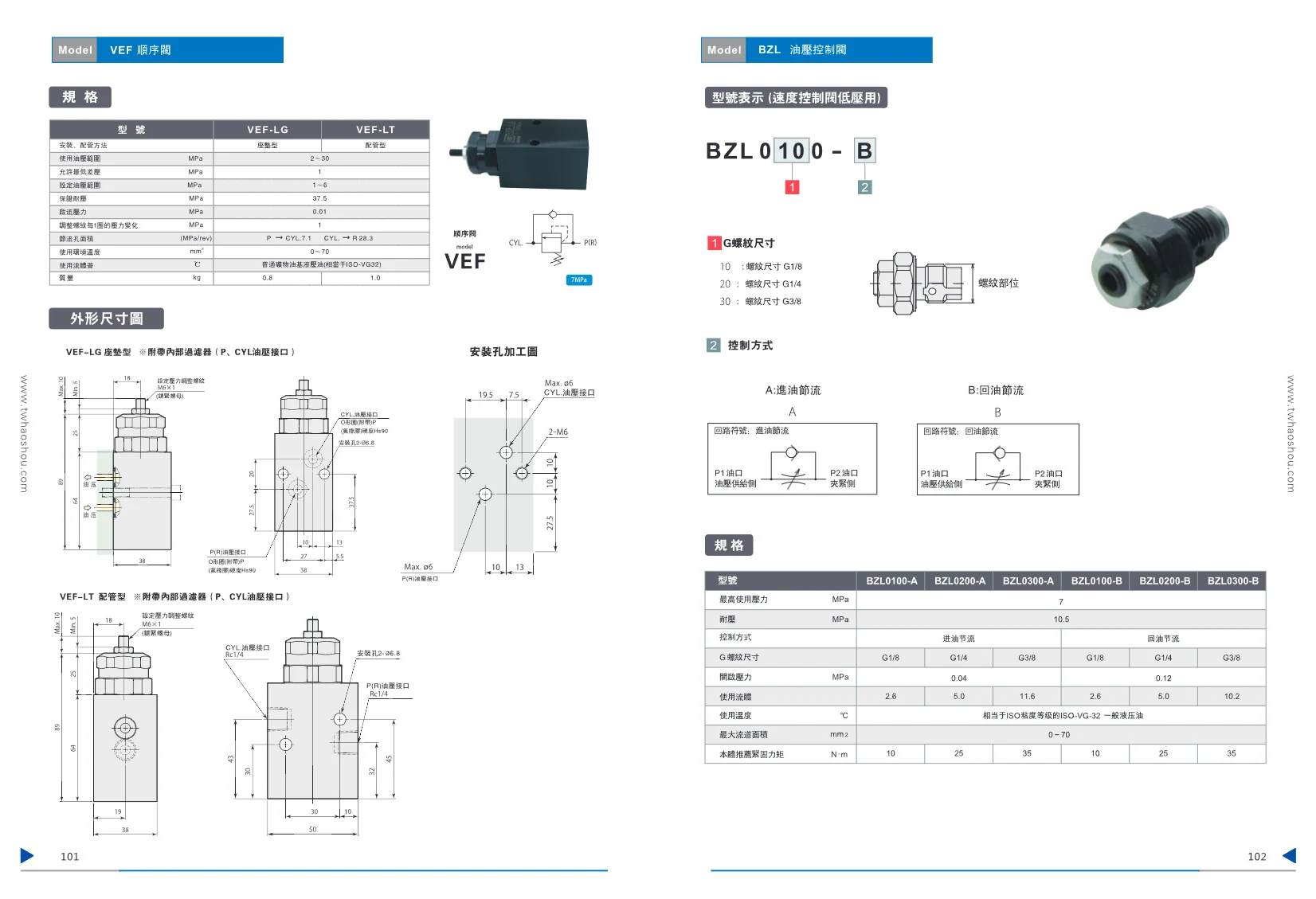
VEF Series Servo Valve
VEF Series speed control servo valves provide precise speed and directional control in hydraulic systems. Available in subplate-mounted (VEF-LG) and in-line (VEF-LT) configurations. Operating pressure range: 2–30 MPa; minimum allowable differential pressure: 1 MPa; setting pressure range: 1–6 MPa. Optional G1/8, G1/4, and G3/8 threaded ports. Suitable for hydraulic circuits requiring precise speed control.
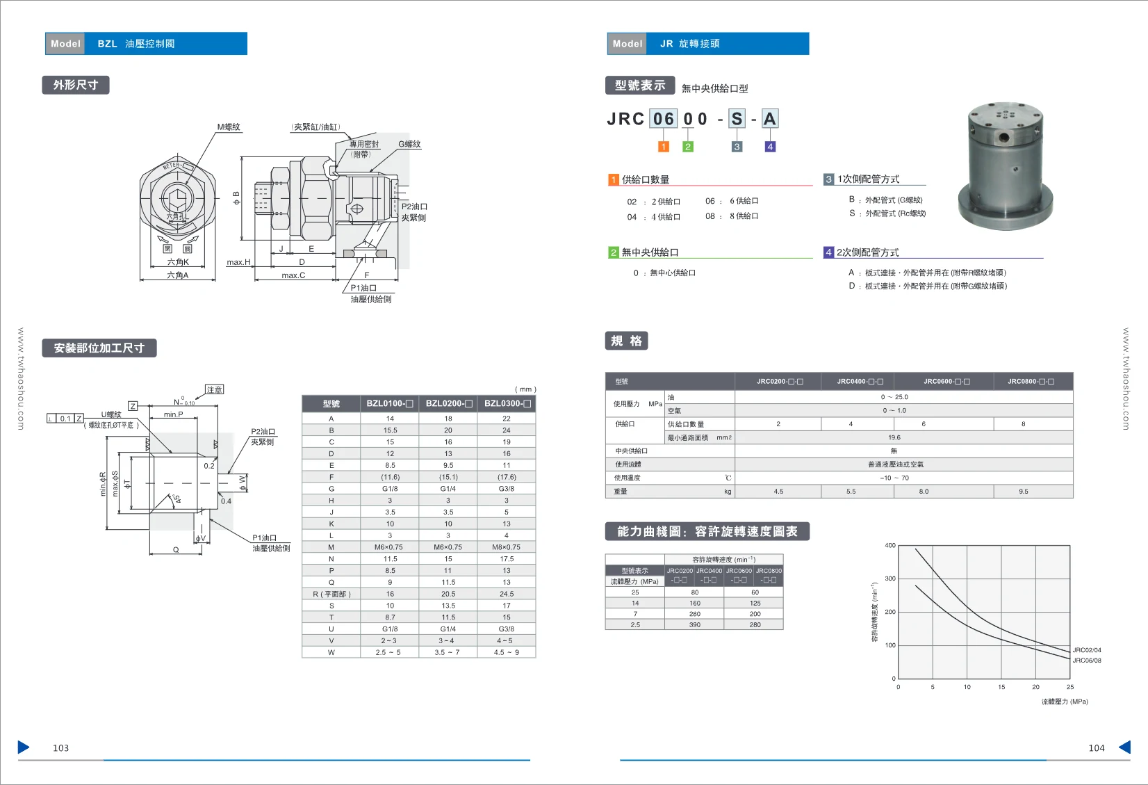
JRC Series Rotary Joints
JRC Series rotary joints without a central supply port deliver oil or air to rotating equipment. Available with 2, 4, 6, or 8 supply ports, each with a minimum flow area of 19.6 mm². Operating pressure: 0–25 MPa for oil and 0–1.0 MPa for air. Operating temperature: −10 to 70°C. The secondary-side piping can be configured for external piping (G or Rc threads). The primary side supports both plate mounting and external piping, with a side port plugged using either a P-threaded or G-threaded plug. Weight varies by number of supply ports, from 4.5 to 9.5 kg. Suitable for applications requiring fluid delivery to rotating equipment, such as automation machinery and rotary tables.
BZL Series Rotary Unions
The BZL series rotary unions includes three basic models—BZL0100, BZL0200, and BZL0300—each with a different bore size and mounting dimensions. Detailed tables list the machined dimensions for each model’s mounting area, including parameters such as A, B, and C, thread sizes (G1/8 to G3/8), and mounting-hole spacing. These unions are designed for pneumatic or hydraulic line connections in machinery. Their compact design makes them easy to install and suitable for a range of operating conditions.

HNS Hydraulic Swing Clamp Cylinder
HNS Series hydraulic swing clamp cylinders are available in bore sizes from Φ25 to Φ63. The swing angle ranges from 0° to 90° (90° standard; 0°, 45°, 60° and 180° available as options). They are suitable for applications requiring high clamping force, such as machining, batch production and highly automated production lines. The cylinder body is made of carbon steel and features a double-acting design with flange mounting. Maximum pressure: 70 kg/cm²; normal operating pressure: 20–45 kg/cm². Two basic types are available: single-arm (HNS) and double-arm (HNSD), along with the HNTS and HNTSD variants (not available with a Φ63 bore). The theoretical clamping force ranges from 59 kg to 600 kg at 25 kg/cm². Use filtered standard hydraulic oil.
HNS Series Hydraulic Swing Clamp
HNS Series hydraulic swing clamps are suitable for applications requiring high clamping force, such as clamping large workpieces or machining operations with high cutting forces. They are widely used in mass production and highly automated production lines. The cylinder body is made of carbon steel for strength and durability. Bore sizes range from Φ25 mm to Φ63 mm, with four subseries available: HNS (single-arm, flange-mounted), HNSD (double-arm, flange-mounted), HNTS (single-arm, special type), and HNTSD (double-arm, special type). Swing angles from 0° to 90° are available, with 90° as standard. Maximum pressure resistance is 70 kg/cm²; the typical operating pressure is 20–45 kg/cm². The design is double-acting with flange mounting. Piston rod diameters vary by bore size and are Φ18, Φ20, Φ20, Φ20, and Φ25 mm, respectively. Theoretical clamping force ranges from 59 kg to 600 kg at a pressure of 25 kg/cm². The ordering code consists of the series number, swing direction, cylinder bore, swing angle, and mounting type, allowing flexible model selection.
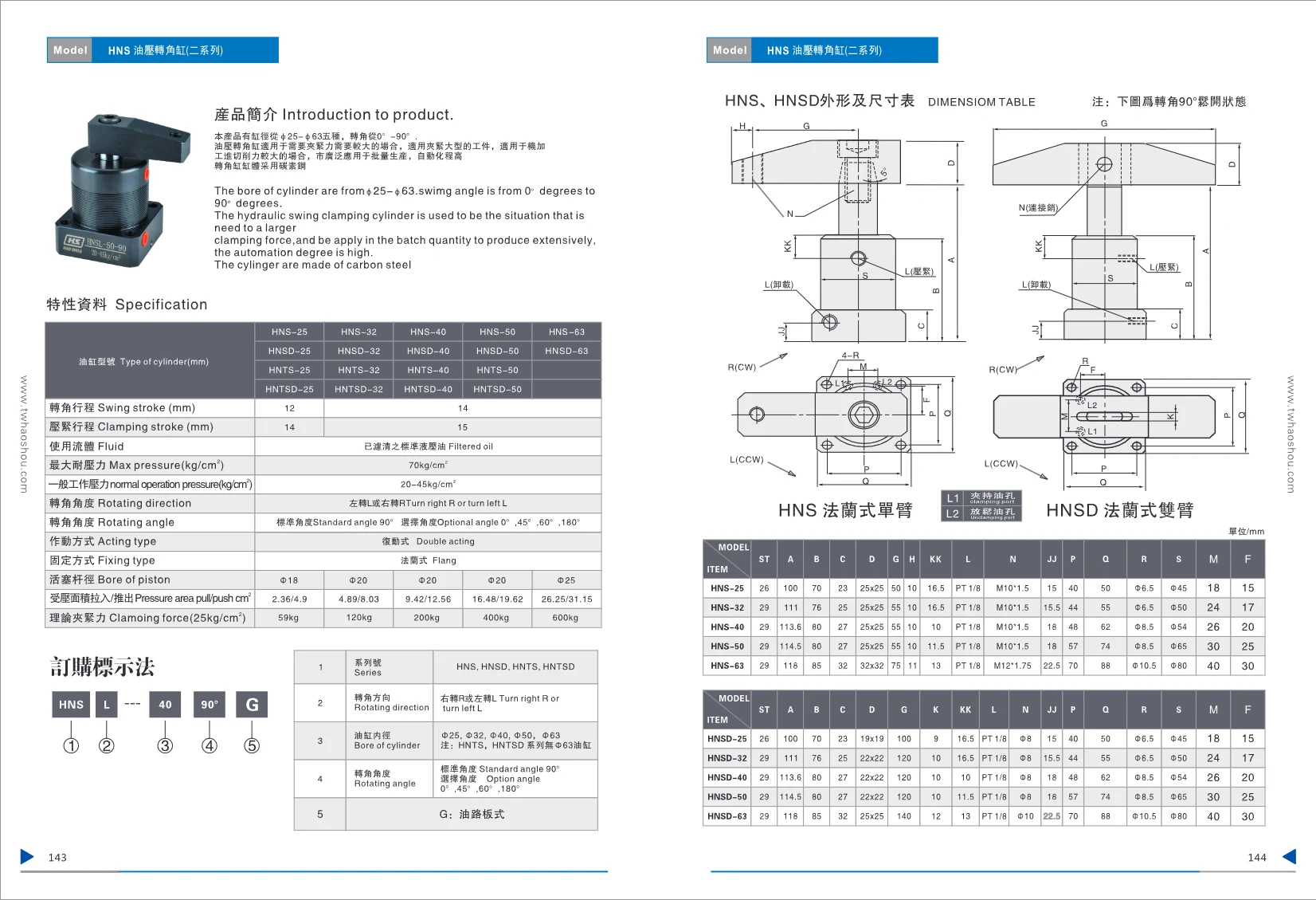
HNTS Series Hydraulic Swing Clamp Cylinders
The HNTS Series Hydraulic Swing Clamp Cylinders comprise two subseries, HNTS and HNTSD. Bore sizes range from Φ25 to Φ50 (excluding Φ63), with a swing stroke of 12–14 mm and a clamping stroke of 14–15 mm. They use standard hydraulic oil and have a maximum pressure rating of 70 kg/cm² and an operating pressure of 20–45 kg/cm². The swing angle ranges from 0° to 180° (90° standard). These double-acting cylinders are flange-mounted and are suitable for applications requiring high clamping force, such as machining fixtures and automated production lines. The theoretical clamping force ranges from 59 to 600 kg at 25 kg/cm². Ordering code format: series - rotation direction - bore - swing angle - mounting style.
HNTSD Series Hydraulic Swing Clamp Cylinders
This oil-hydraulic swing clamp cylinder series comprises four subseries: HNS, HNSD, HNTS, and HNTSD. Bore sizes range from Φ25 to Φ63, swing strokes from 12 to 14 mm, and clamping strokes from 14 to 15 mm. The cylinders use standard hydraulic oil, have a maximum pressure rating of 70 kg/cm², and operate at 20–45 kg/cm². The standard swing angle is 90°, with 0°, 45°, 60°, and 180° options available. They feature a double-acting design and flange mounting, and come in single-arm (HNS, HNTS) and double-arm (HNSD, HNTSD) configurations. The theoretical clamping force ranges from 59 to 600 kg at 25 kg/cm², making them suitable for applications requiring high clamping force. They are widely used in mass production and automated machining. The ordering code consists of the series number, swing direction, bore size, swing angle, and mounting option G.
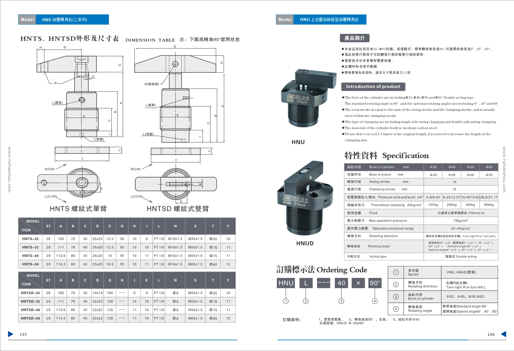
HNU Series Upper-Flange Manifold-Mounted Hydraulic Swing Clamp Cylinder
This series comprises HNU-type, upper-flange manifold-mounted hydraulic swing clamp cylinders, available in single-arm (HNU) and double-arm (HNUD) versions. Four bore sizes are available, from Φ32 to Φ63. The cylinders feature a double-acting design and a standard swing angle of 90°, with 0°, 45° and 60° options. The total stroke is the sum of the swing stroke and clamping stroke: 14 mm and 15 mm, respectively. The cylinder body is made of medium-carbon or carbon steel, with a specially machined inner wall for a smooth surface and long service life. Axial and side manifold-mounting options are available, eliminating piping for a neat, space-saving installation. The operating pressure range is 20–45 kg/cm² for swing clamp cylinders or 5–140 kg/cm² for thin-type cylinders. The operating temperature range is -10 to +60°C. Use filtered, standard hydraulic oil as the operating fluid. The theoretical clamping force is calculated according to the bore size and operating pressure, and can reach several hundred kilograms. The order code consists of the series designation, rotation direction, bore size and angle; for example, HNUD R-50x90°.
HNU / HNUD Hydraulic Swing Clamp Cylinder
This series consists of double-acting hydraulic swing clamp cylinders with four bore sizes: Φ32, Φ40, Φ50, and Φ63. The standard swing angle is 90°, with 0°, 45°, and 60° available as options. The total stroke consists of the swing stroke and the clamping stroke. Clamping arms are available in single-arm and double-arm configurations. The cylinder body is made of medium-carbon steel. Clamp arm extensions must not exceed 1.5 times the original length. The operating pressure range is 20–45 kg/cm², and the maximum pressure resistance is 70 kg/cm². The cylinder can rotate to the right or left. The ordering code consists of the series number, rotation direction, bore size, and angle.

HTB Compact Hydraulic Cylinder
The HTB compact hydraulic cylinder series is designed for automation equipment where space is limited. It offers a variety of mounting configurations, including axial single-/double-rod types (SD/SW), axial manifold-mount types (SDMA/SDMB), side single-/double-rod types (LA/LW), and side-mounted keyed types (LAM/LWM). Bore diameters range from φ20 to φ80 mm, depending on the mounting configuration, with standard strokes of 5 to 50 mm. The rod end is available with an internal thread (N) or external thread (W). The operating pressure is ≤10 MPa; a stainless steel cylinder body is required for higher pressures. The overall dimensions comply with industry standards, allowing interchangeability with products from international brands.
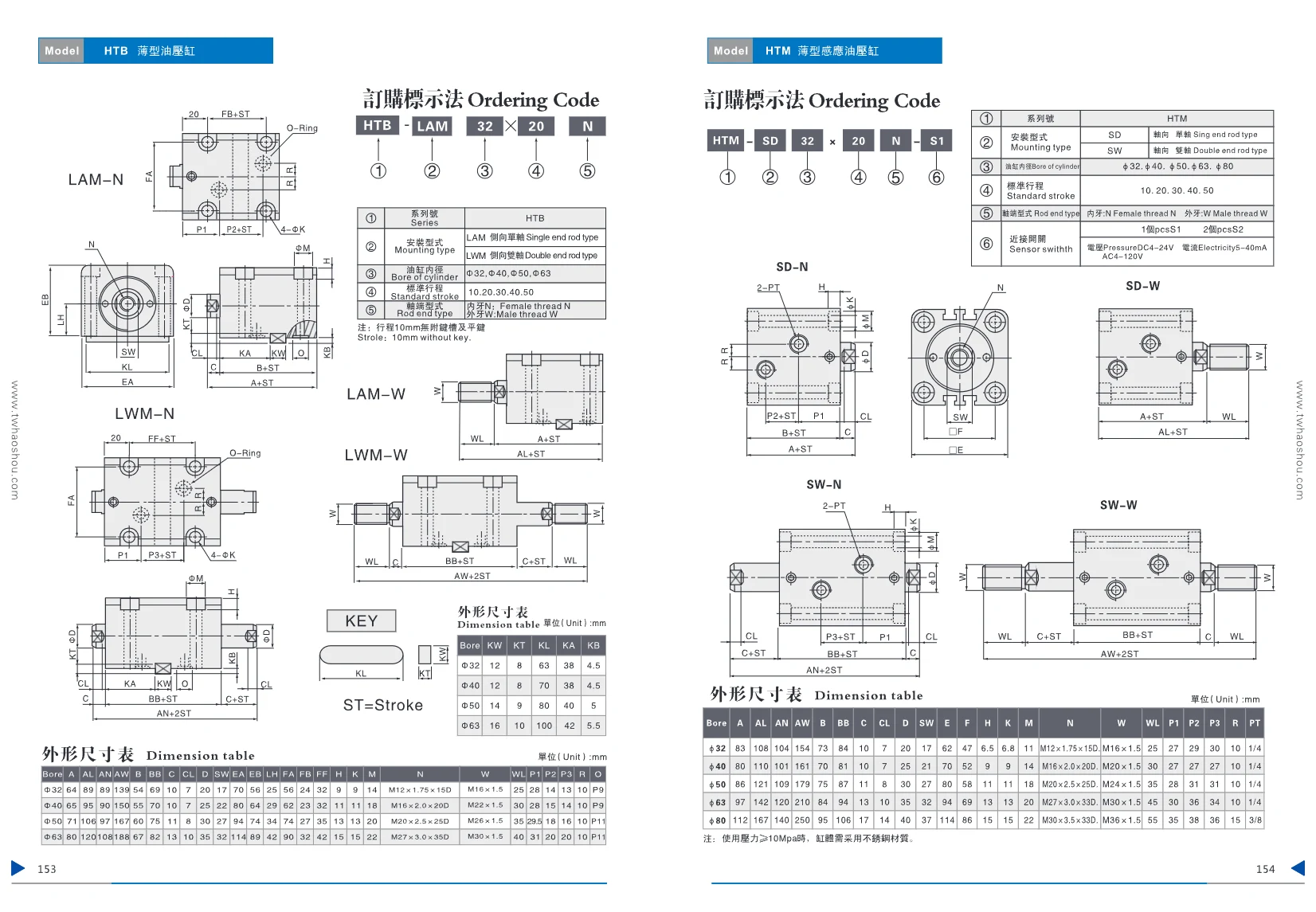
HTM Series Compact Hydraulic Cylinder
HTM Series compact hydraulic cylinders are available with axial single-rod (SD) or double-rod (SW) configurations. Bore sizes are φ32, φ40, φ50, φ63, and φ80 mm, with standard strokes of 10, 20, 30, 40, and 50 mm. Rod ends are available with internal threads (N) or external threads (W). Proximity switches are optional (one S1 or two S2). Cylinder body material is selected according to operating pressure; stainless steel is required for pressures ≥10 MPa. Standard dimensions and easy installation make these cylinders suitable for automation equipment where space is limited.

HBC Series Hydraulic Cylinders
These hydraulic cylinders are built to standard dimensions and use imported seals to ensure reliable sealing. Their standardized specifications provide a high degree of interchangeability. They support both axial and side mounting, and are available in single-acting, normally retracted and double-acting configurations. The cylinder body and clamping mechanism are made of durable carbon steel for mechanical structures. The piston is made of heat-treated 45# steel with a chrome-plated surface. Use filtered standard hydraulic oil. The maximum pressure resistance is 70 kg/cm², and the operating pressure range is 10–50 kg/cm².
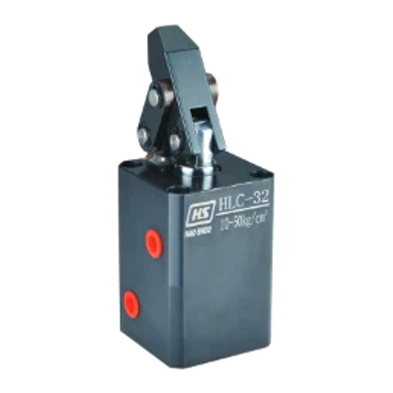
HLC Series Lever-Type Hydraulic Cylinder
The HLC series lever-type hydraulic cylinders are built to German specifications. Imported oil seals ensure pressure-resistant sealing, and the standardized design offers high interchangeability. They can be mounted axially or laterally and are available in single-acting, normally engaged and double-acting versions. The cylinder body and clamping mechanism are made of durable carbon steel; the piston is made of 45# steel, heat-treated and chrome-plated. Bore sizes of 25, 32, 40, 50, and 63 mm and several mounting styles are available (MF flange, FA axial, line, and manifold types). Stroke: 25–40 mm. Maximum pressure resistance: 70 kg/cm². Operating pressure range: 10–50 kg/cm². Theoretical clamping force varies with bore size and pressure, reaching up to 701 kg (63 mm bore at 30 kg/cm²). Suitable for industrial applications such as automated clamping and positioning.