Hydraulic Components — Page 2

HTC Series Hydraulic Cylinders
HTC series compact, externally threaded, single-acting hydraulic cylinders use imported seals and components to minimize oil leakage. They remain leak-free for extended periods under high-pressure clamping. Their compact size makes them suitable for arranging in the limited space available in fixtures. These are single-acting cylinders with spring return and must not be used for pulling applications. Install them as perpendicular to the work surface as possible, with an inclination of no more than 10°. The operating pressure range is 20–250 kg/cm². Piston rod diameters are available in four sizes: Φ12, Φ16, Φ20, and Φ25. The corresponding total strokes are 10, 12, 15, and 16 mm, respectively. The theoretical clamping force at 200 kg/cm² ranges from 200 kg to 980 kg. The ordering code consists of the series designation HTC, the piston rod diameter (12/16/20/25), and the type (A or B), for example, HTC-16A. The difference between types A and B is that type B has a side oil port (dimension N), while type A does not.
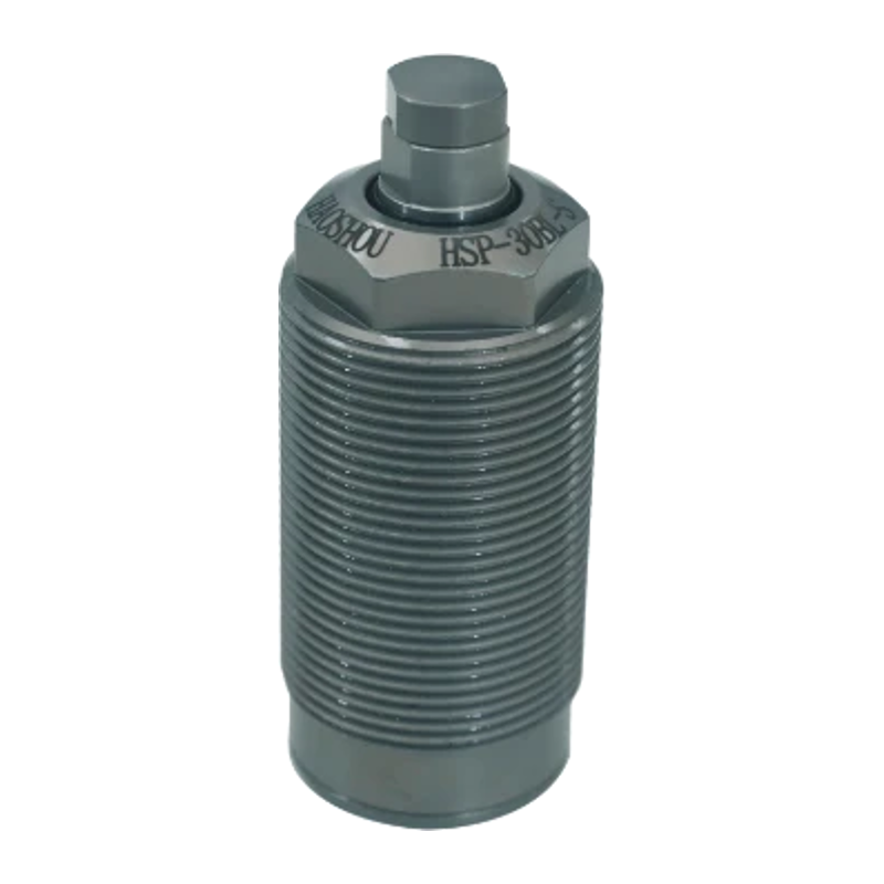
HSP Support Cylinder
HSP Series support cylinders feature a sleeve and dual-piston design, delivering high support force with low-pressure hydraulic oil at 2–7 MPa. Their mounting dimensions are compatible with common products on the market. They are compact, reliable, and long-lasting. The piston rod applies a contact force of just 0.3–0.8 kgf to the workpiece, making these cylinders suitable for workpieces of all types. Their compact size and four thread sizes (M26–M45) allow installation in tight spaces without changing the fixture base dimensions. Two operating types are available: Type A (spring-down) and Type B (hydraulic-up). They are single-acting and operate at 20–70 kgf/cm². The HSP-16 subseries is designed for high-pressure applications from 100 to 250 kgf/cm². Common applications include fixture positioning and workpiece support.

HSF Series Hydraulic Cylinders
The HSF series includes two types: support cylinders and swing clamp cylinders. Support cylinders are available in Type A (clamping support) and Type B (rising support). They feature a compact design, an operating pressure of 2–7 MPa, a stroke of 8–20 mm, and a piston rod diameter of 15–30 mm. Support force increases with pressure, ranging from 385 to 4,550 kgf at 70 kgf/cm². Swing clamp cylinders require no pre-drilled mounting holes and can be mounted directly on the worktable. They are available in single-acting and double-acting versions, with an operating pressure of 35–250 kg/cm² and a theoretical clamping force of 180–1,960 kg. The standard swing angle is 90°, with 30°, 45°, and 60° options available on request. The carbon-steel cylinder body is carburized and nitrided for wear resistance. Mounting dimensions are compatible with products available on the market.

HPS High-Pressure Swing Clamp Cylinder
The HPS Series High-Pressure Swing Clamp Cylinder keeps the area clear for loading and unloading workpieces while providing high-pressure clamping. The hydraulic cylinder clamps downward and has a swing stroke (do not clamp the workpiece during this stroke) followed by a vertical clamping stroke. This product uses German-made oil seals and imported components. The cylinder bore is specially machined to provide a smooth surface, ensuring reliable performance and long service life. Available bore diameters are 25, 40, 50, and 63 mm. The swing stroke is 7–12 mm, the vertical stroke is 11–15 mm, the maximum oil filling speed is 3.2–27.7 cc/s, and the minimum operating pressure is 40 kg/cm². Choose a clockwise right-hand swing (R) or a counterclockwise left-hand swing (L); the standard swing angle is 90°. Mounting options include fully threaded type A, base type B (piped), and manifold type C. Operating modes are single-acting (S) and double-acting (D).

HB Hydraulic Booster Valve
This series of hydraulic booster valves features a built-in hydraulic sequence valve. Using a pre-pressure design, it fills the actuator cylinder with oil and initiates sequential operation once the preset pressure is reached, multiplying the pressure. It is suitable for dedicated hydraulic machines and applications requiring high-pressure operation in low-pressure circuits on MC fixtures. The HB booster can be operated with just one solenoid valve or installed directly in the piping. It automatically converts low-pressure oil to high-pressure oil for high-pressure clamping. Models include HB-9×6, HB-8×22, HB-5×35, and HB-3.8×45, with boost ratios of 9, 8, 5, and 3.8, respectively, and high-pressure output volumes of 6 cc, 22 cc, 35 cc, and 45 cc, respectively. Overall and mounting dimensions vary by model. An adjustment guide for the SV hydraulic sequence valve is provided. The factory-set pressure is 30 kg/cm².

HSV Hydraulic Sequence Valve
HSV series hydraulic sequence valves are especially suitable for fixture circuits, where pressure determines the operating sequence of the hydraulic cylinders. Compact and rated for high pressure, these valves provide sequential operation when installed in the circuit, without requiring additional controls. Two mounting options are available: Type A (manifold-mounted) and Type B (pipe-connected), allowing flexible selection to suit the overall fixture design. Two pressure adjustment ranges are offered—25–250 kg/cm² and 10–70 kg/cm²—to meet different application requirements.

HLG Series Sequence Valves
HLG series sequence valves (sequence pressure control valves) control the sequential operation of actuators in hydraulic systems. Two pressure adjustment ranges are available: 1.0–6.0 MPa for the HLG-3A and 5.0–18.0 MPa for the HLG-6A. Their operating pressure ranges are 2.0–35.0 MPa and 6.0–35.0 MPa, respectively. The pressure change per turn of the adjustment screw is 1.0 MPa and 2.8 MPa, respectively, and the cracking pressure is 0.01 MPa. Suitable for temperatures from 0 to 70°C and ISO VG 32 hydraulic oil. When ordering, specify the model, manifold plate type, and set pressure.
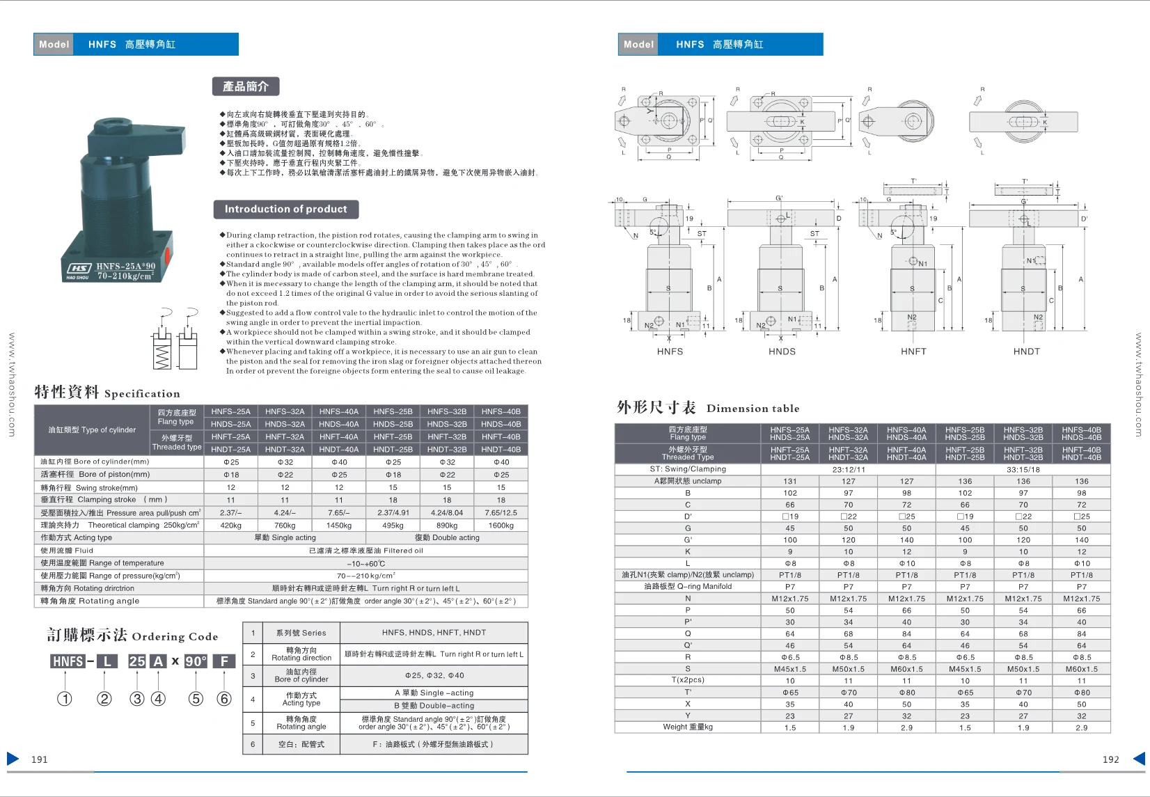
HNFT High-Pressure Swing Clamp Cylinder
The HNFT Series High-Pressure Swing Clamp Cylinder is made of premium carbon steel with a hardened surface. The standard swing angle is 90°, with custom angles of 30°, 45°, and 60° available. Clamping is achieved by rotating left or right and then pressing vertically downward. Cylinder bore sizes are 25 mm, 32 mm, and 40 mm. Two operating types are available: single-acting (Type A) and double-acting (Type B). The theoretical clamping force ranges from 420 kg to 1,600 kg at a pressure of 250 kg/cm². Use clean, filtered hydraulic oil. The operating temperature range is -10 to +60°C, and the pressure range is 70 to 210 kg/cm². Installing a flow control valve at the oil inlet is recommended to control the swing speed. Suitable for automated clamping applications.
HNDT High-Pressure Swing Clamp Cylinder
The HNDT series high-pressure swing clamp cylinder clamps by rotating and then pressing vertically downward. The standard rotation angle is 90°; angles of 30°, 45° and 60° are available by custom order. Made of high-grade carbon steel with a hardened surface. When the clamp arm is extended, the G value exceeds 1.2 times that of the original specification. Install a flow control valve before use to control the swing speed. Available in single-acting or double-acting versions. Use filtered hydraulic oil. Operating temperature: -10 to +60°C; pressure range: 70–210 kg/cm². Choose clockwise rotation (R) or counterclockwise rotation (L). Cylinder bore sizes are 25 mm, 32 mm and 40 mm. Piping options are pipe-connected (blank) and manifold-mounted (F).

HPRV Hydraulic Pressure Reducing Valve
The HPRV series hydraulic pressure reducing valve regulates inlet pressure to maintain a stable outlet pressure. It is suitable for applications requiring pressure reduction in hydraulic systems. The product includes a hydraulic circuit diagram, with oil flowing out through port A and entering through port P. Detailed technical specifications are not provided on this page; please refer to the complete catalog.

HFCV Hydraulic Flow Control Valve
The HFCV series hydraulic flow control valves regulate fluid flow in hydraulic systems. They are available in two models, HFCV-01 and HFCV-02, with different port and overall dimensions. The valves feature an integrated body design with excellent sealing and dust resistance, making them suitable for harsh environments. The working medium is standard hydraulic oil. The operating temperature range is -10 to 70°C, and the maximum pressure resistance is 100 kg/cm². Mounting dimensions include parameters A, B, C, D, Φ, E, F1, and F2. The port threads are PT1/8 and PT1/4, respectively.
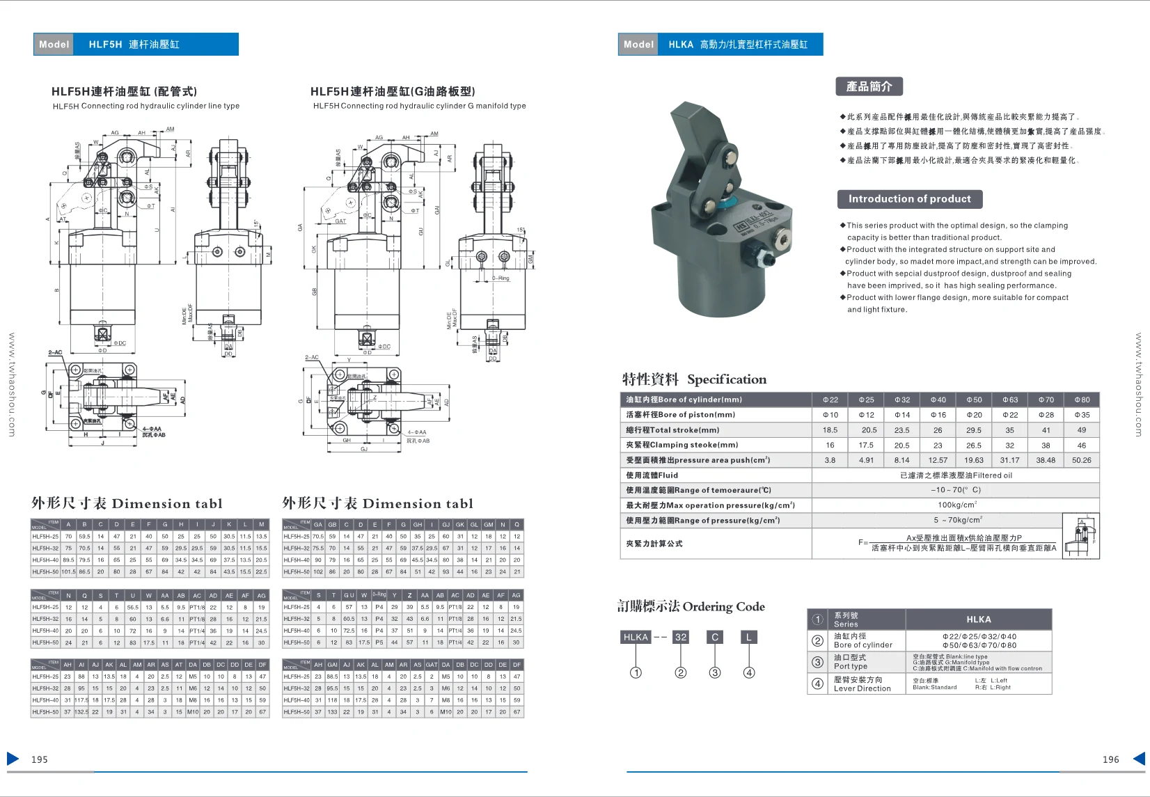
HLKA Series Hydraulic Clamping Cylinder
The HLKA Series hydraulic clamping cylinder features an integrated design for greater strength and improved sealing. Cylinder bore sizes include Φ22, Φ25, Φ32, Φ40, Φ50, Φ63, Φ70, and Φ80. Total stroke ranges from 18.5 mm to 49 mm, with a clamping stroke of 16 mm to 46 mm. Operating pressure ranges from 5 to 70 kg/cm², and maximum pressure resistance is 100 kg/cm². Suitable for filtered standard hydraulic oil, it operates at temperatures from -10 to 70°C. Optimized accessory design improves clamping capacity. Available port configurations include piped, manifold-mounted, and manifold-mounted with speed control. The pressure arm can be installed in the standard, left, or right orientation. Ideal for use in fixtures, automation equipment, and other applications.
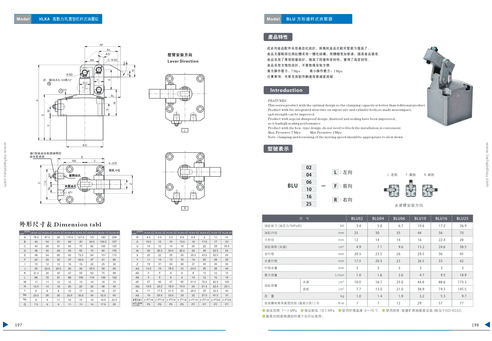
HKLKA Series Hydraulic Cylinders
HKLKA series hydraulic cylinders feature a compact, square design for easy installation. Available in eight sizes—22, 25, 32, 40, 50, 63, 70, and 80—to suit clamping and positioning applications with different load requirements. Bore diameter accuracy is available in grades P5 or P7 to ensure precise positioning. For installation dimensions, see the dimensional drawings, which include parameters A through AZ.

BLU Square Linkage Clamp
The BLU Square Linkage Clamp is an optimally designed hydraulic clamping device that offers high clamping force, a compact structure, and excellent sealing. Its integrated cylinder body improves overall strength and dust-resistant sealing, while the regular square shape makes installation easy and requires no additional adjustment. The maximum operating pressure is 7 MPa and the minimum is 1 MPa. The operating temperature range is 0–70°C. It is compatible with standard mineral-oil-based hydraulic fluid (ISO VG 32). The range includes six sizes, from BLU02 to BLU25, with cylinder bore diameters of 25–70 mm, clamping forces of 3.4–26.9 kN (at 7 MPa), total strokes of 20.5–45 mm, and clamping strokes of 17.5–42 mm to meet a variety of clamping requirements. Suitable for use in environments where fluorine-based cutting fluid is sprayed.

HCTU Series Rotary Clamp Cylinders
The HCTU series comprises top-flange, high-speed, double-acting hydraulic rotary clamp cylinders. A Gothic-arch cam groove and three-point steel-ball support mechanism ensure smooth, high-speed rotation and long service life. At a hydraulic pressure of 7 MPa, cylinder force ranges from 2.4 kN (HCTU01) to 25.8 kN (HCTU25), while clamping force ranges from 2.0 kN to 21.2 kN. Clamping arm lengths range from 30 to 90 mm. Options include a double-ended rod (E), a top pin (P), and rotation angles of 30°, 45°, or 60° (N30/N45/N60). The rotation direction can be left (L) or right (R). Piping options include differential-pressure piping or G-thread piping. The clamping arm is supplied by the user; HCTH series clamping arms are available for use with these cylinders.
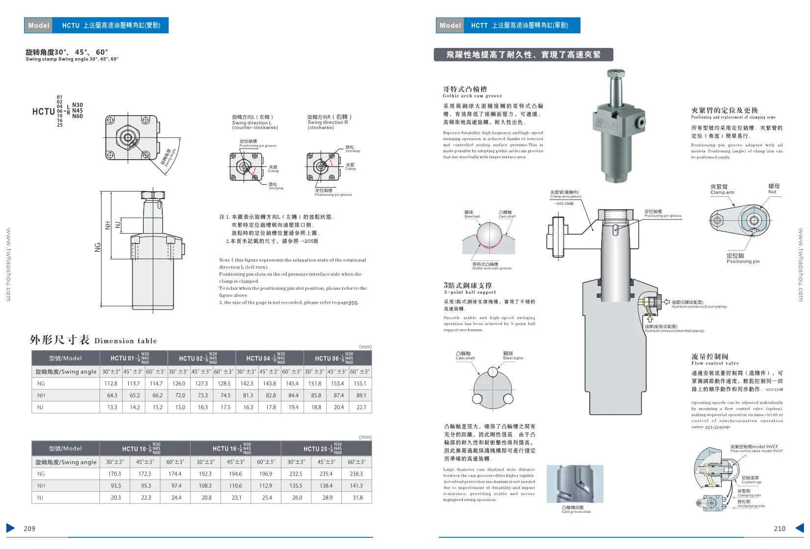
HCTT Up-Flange-Mounted High-Speed Hydraulic Swing Clamp Cylinder (Single-Acting)
The HCTT series is a high-speed, up-flange-mounted hydraulic swing clamp cylinder (single-acting). It features a Gothic cam groove and a three-point ball support mechanism. The balls make broad contact with the cam groove, effectively reducing contact pressure and enabling continuous, high-frequency, high-speed rotation with excellent durability. Seven sizes are available, from HCTT01 to HCTT25. At 7 MPa, cylinder force ranges from 2.0 to 20.5 kN, clamping force from 1.7 to 16.8 kN, and standard clamp arm length from 30 to 90 mm. Choose from rotation angles of 30°, 45°, or 60°. The rotation direction is clockwise during clamping. The model code indicates size, rotation direction, and special features. Variants include standard angle A, specified angles N30/N45/N60, and a locating-pin option P. Suitable for automated fixture systems requiring fast, frequent clamping.

HBTU Series Rotary Clamp Cylinder
The HBTU Series square-body, high-speed hydraulic rotary clamp cylinder features a Gothic cam groove and a three-point steel-ball support mechanism for smooth, high-speed rotation and excellent durability. Its large-diameter camshaft offers high rigidity, enabling stable high-speed rotation without an overload protection mechanism. Two connection options are available: G-thread piping and face-seal piping. The clamp arm is easy to position and replace using the locating pin slot. A flow control valve (model HVCF) can be added to adjust the operating speed independently, enabling convenient sequential or synchronized control. The square cylinder body is compact and requires no spacer blocks. Six sizes are available, from HBTU02 to HBTU25, with cylinder forces at 7 MPa ranging from 2.8 to 25.8 kN and clamping forces from 2.4 to 21.2 kN. Clamp arm lengths range from 35 to 90 mm, cylinder bore diameters from 29 to 82 mm, rod diameters from 18 to 36 mm, and effective areas from 10 to 23 cm². Ideal for automated production lines requiring high-speed rotary clamping.
HCTH Clamping Arms
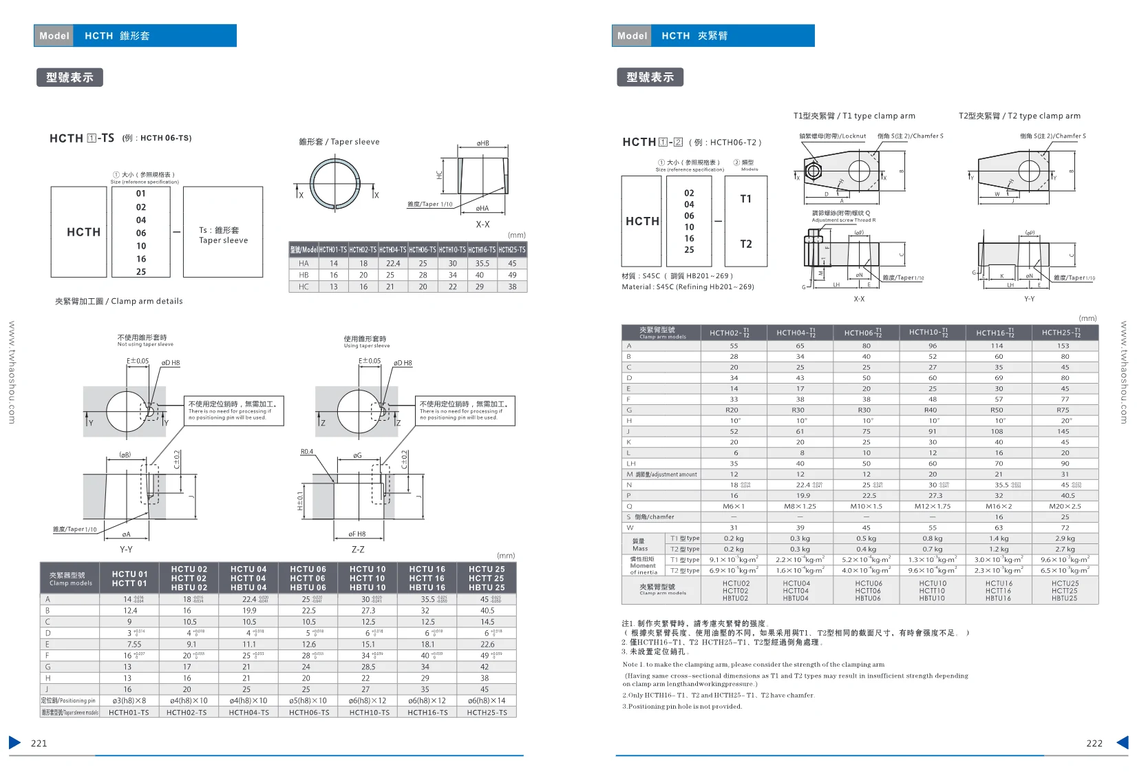
The HCTH series of clamping arms includes two types: taper sleeves (TS) and T1/T2 clamping arms. TS sizes range from 01 to 25, while T1/T2 sizes range from 02 to 25. Made from high-strength materials, these arms offer high rigidity and reliability, making them suitable for workpiece clamping and positioning in automation equipment. Detailed dimensions are provided for the T1/T2 types, including mounting holes, length, width, and angle, as well as mass and moment of inertia. The TS type features a taper-sleeve design for tensioning or positioning. None of the models have locating-pin holes. The T1/T2 types of HCTH16 and HCTH25 are chamfered.
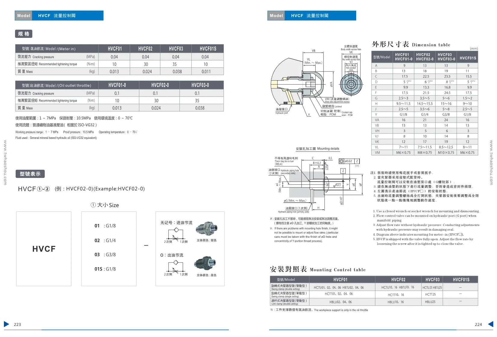
HVAC Flow Control Valve
The HVAC series flow control valves regulate inlet flow in hydraulic systems. Available models include HVAC01, HVAC02, HVAC03, and HVAC01S. The valve body is made of metal, and the hydraulic oil ports use standard sizes. Suitable for fluid control in industrial automation applications.

HCP Series Crank-Type Hydraulic Clamp
The HCP Series crank-type, dual-slider synchronous cylinder uses a crank-slider mechanism to achieve synchronized motion and provides a long slider stroke. All sliding surfaces are hardened and precision-ground, and are lubricated directly, delivering high clamping accuracy and effective protection against chips. The HCP-30-S model features an adjustable stroke. Suitable for applications requiring high-precision clamping, such as machine-tool fixtures and welding fixtures. Use filtered standard hydraulic oil. Operating temperature: -10 to 70°C; operating pressure: 10 to 35 kg/cm².

MOB Light-Duty Hydraulic Cylinder
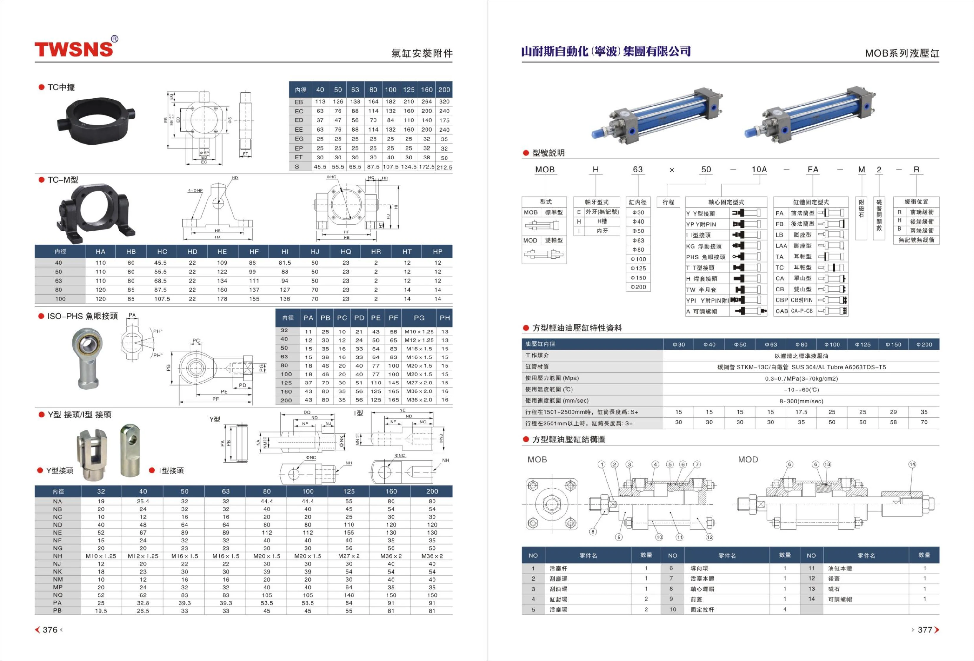
The MOB series comprises light-duty hydraulic cylinders that comply with the GB/T 15622-1995 standard. High-performance seals prevent leakage and provide a long service life. The end caps are made of 45 steel, and the piston rod is hard-chrome plated for a sturdy, durable construction. Bore diameters range from 30 to 125 mm; operating pressure is 0.3–7.0 MPa (3–70 kg/cm²), the temperature range is -10 to +60°C, and operating speed is 8–300 mm/s. A variety of mounting options are available, including SD, FA, FB, LB, TC, CA, CB, CBP, and CAB, to suit different design requirements. For standard strokes, piston length varies with bore diameter; special strokes can be made to order. When ordering, specify the type, cushioning method, bore diameter, piston-rod diameter, stroke, mounting style, and any other accessories.
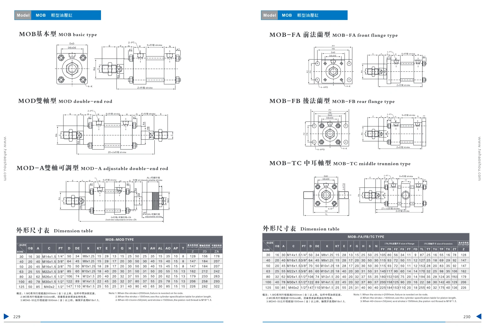
MOB Series Light-Duty Hydraulic Cylinders
The MOB series comprises light-duty hydraulic cylinders available in a basic model (MOB), a double-rod model (MOD), an adjustable double-rod model (MOD-A), and several mounting configurations: front flange (MOB-FA), rear flange (MOB-FB), and center trunnion (MOB-TC). Bore sizes range from 30 to 125 mm, with corresponding piston rod diameters of 16 to 50 mm. PT port sizes range from 1/4" to 1/2", and piston rod threads from M8x1.25 to M16x1.5. Depending on the model, standard strokes can exceed 2,000 mm. For strokes over 2,000 mm, a support bracket must be added at the midpoint of the tie rods. For strokes over 1,500 mm, adjust the piston length according to the cylinder specifications table. For 40–50 mm bore sizes with strokes of 1,500 mm or more, the piston rod thread changes to M16x1.5. The dimensional tables provide detailed mounting dimensions for each size. These cylinders are suitable for light-duty hydraulic applications.
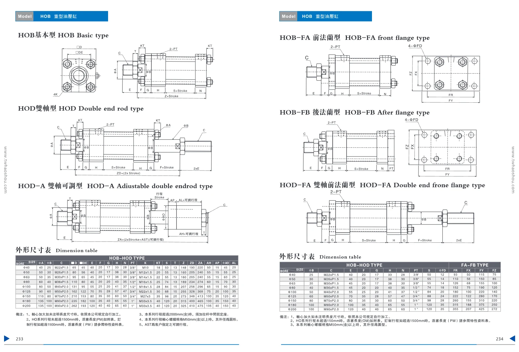
HOB Heavy-Duty Hydraulic Cylinder
The HOB series comprises heavy-duty hydraulic cylinders designed for demanding applications such as hydraulic fixtures. A range of mounting configurations is available: basic type (single piston rod), double-rod type, front-flange type, rear-flange type, center-trunnion type, front-trunnion type, single-clevis type, double-clevis type, left-and-right-foot type, and front-and-rear-foot type. Bore sizes range from Φ40 to Φ200. Standard stroke lengths are listed in the dimensional drawings. Strokes over 1,500 mm require special design; strokes over 2,000 mm require an intermediate support. For shaft nut sizes M50 and above, the outside diameter is round. Adjustable strokes can be customized. The operating pressure is not specifically stated; however, by industry standards, heavy-duty hydraulic cylinders typically reach 14–21 MPa. The series features a compact design and flexible mounting options, making it suitable for clamping, pushing, pulling, and similar industrial automation applications.

HAS Series Variable-Frequency Hydraulic Power Unit
This hydraulic power unit is especially suitable for hydraulic fixtures. Its powerful features include a compact design, variable-frequency control, and pressure retention. It meets customers’ requirements for low oil temperature, low energy loss, and low noise, and can be customized to order. Available motor power: 1 HP, 2 HP, 3 HP, or 5 HP. Pump options: variable-displacement piston pump (AP) or gear pump (GP), with displacements of 8, 12, 16, or 22 cm³/rev. Pressure ranges: A (10–40 kgf/cm²), B (15–70), C (20–140), or D (25–210). Standard voltages: AC 220 V or AC 380 V. Tank capacities: 10 L, 20 L, 30 L, 40 L, 60 L, or 80 L.
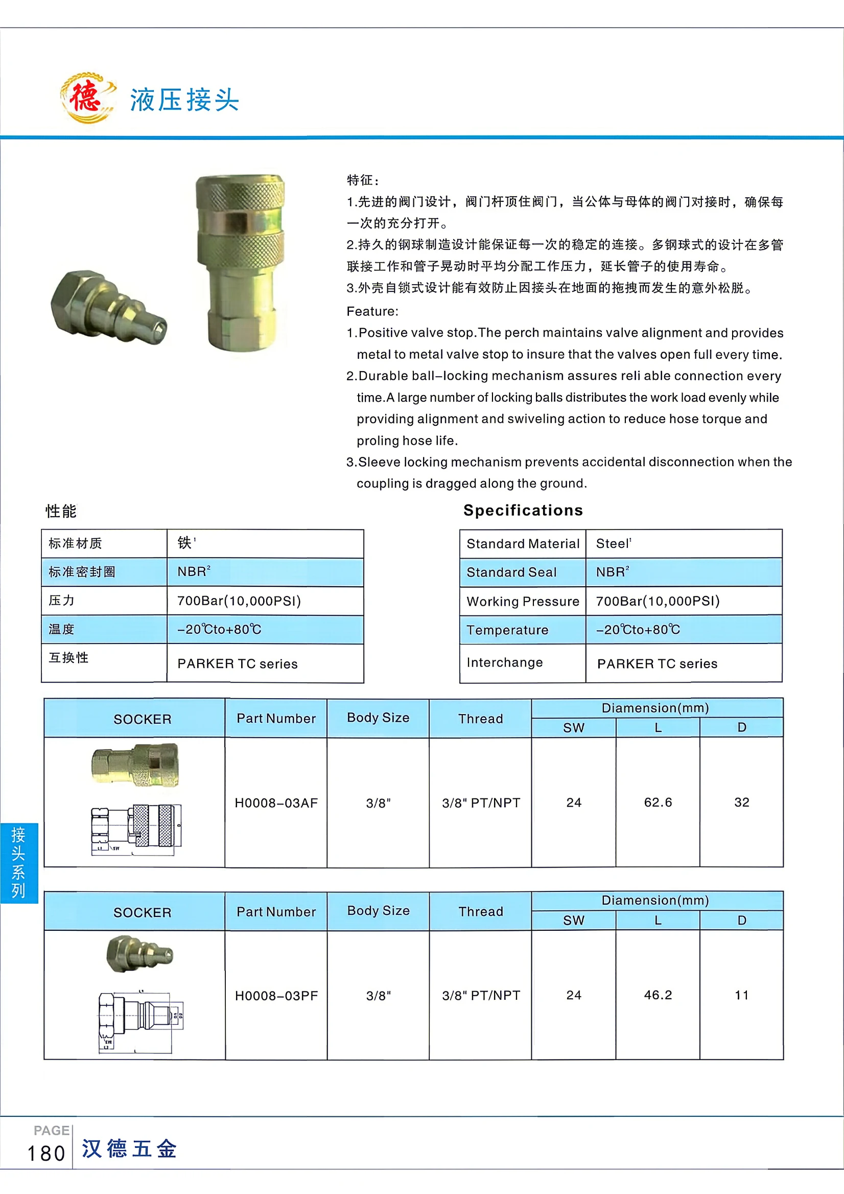
TC Series Hydraulic Couplings
The TC Series Hydraulic Coupling is a high-pressure quick coupler with a working pressure of up to 700 bar (10,000 psi) and a temperature range of -20°C to +80°C. Its advanced valve design ensures the valves open fully, while the multi-ball locking mechanism distributes the load evenly to extend hose service life. A self-locking sleeve prevents accidental disconnection. The standard material is steel, with NBR seals. The couplings are interchangeable with the PARKER TC Series. Suitable for hydraulic line connections, they are widely used in industry, construction machinery and other applications.
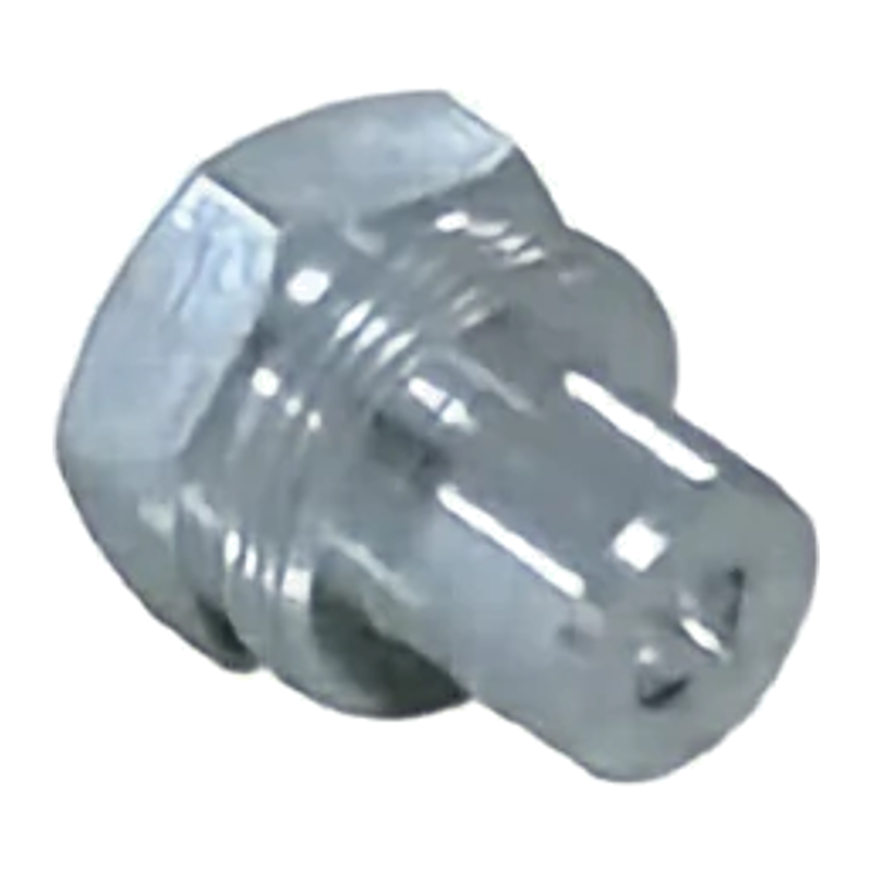
CT-JOINT H0010 Series
This series comprises CT-JOINT H0010 quick couplings, precision-machined from steel for excellent durability. The female coupling uses a threaded-sleeve locking mechanism and mates with a male plug featuring external threads; the connection must be made by hand. The valve uses a hard-seat valve or an aluminum-alloy steel ball with a spring to ensure secure valve seating. The seal is made of polyurethane rubber and resists extrusion under high pressure. Available in 1/4" and 3/8" sizes, the standard material is steel and the seal is NBR. Maximum working pressure is 700 bar (10,150 PSI), and the operating temperature range is -20°C to +80°C. Interchangeable with the Parker 3000 Series and Faster PVVM Series.
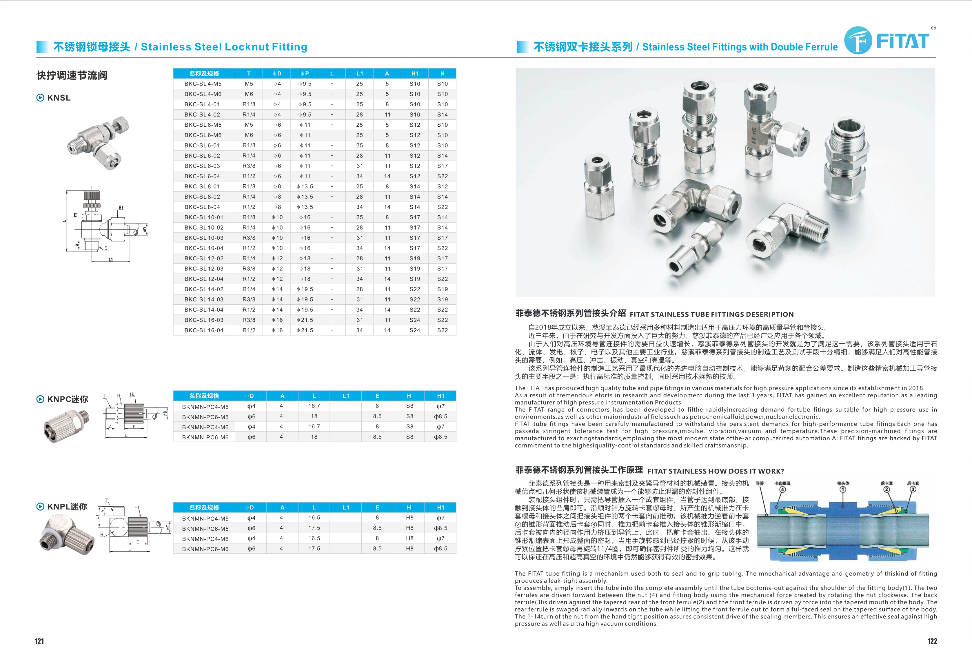
BKNNM-PC Series Stainless Steel Tube Fittings
The BKNNM-PC series comprises FITAT stainless steel tube fittings with a double-ferrule sealing and gripping design. During assembly, the tube is inserted into the fitting body until it reaches the shoulder. Tightening the ferrule nut compresses the front and rear ferrules radially against the tube and creates a seal against the tapered surface of the fitting body. The series is suitable for high-pressure, shock, vibration, vacuum, and high-temperature conditions and is commonly used in petrochemical, fluid handling, power generation, nuclear, and electronics piping systems. The catalog lists φ4 and φ6 tube diameters, M5 and M6 threads, and installation dimensions including L, E, H, and H1.
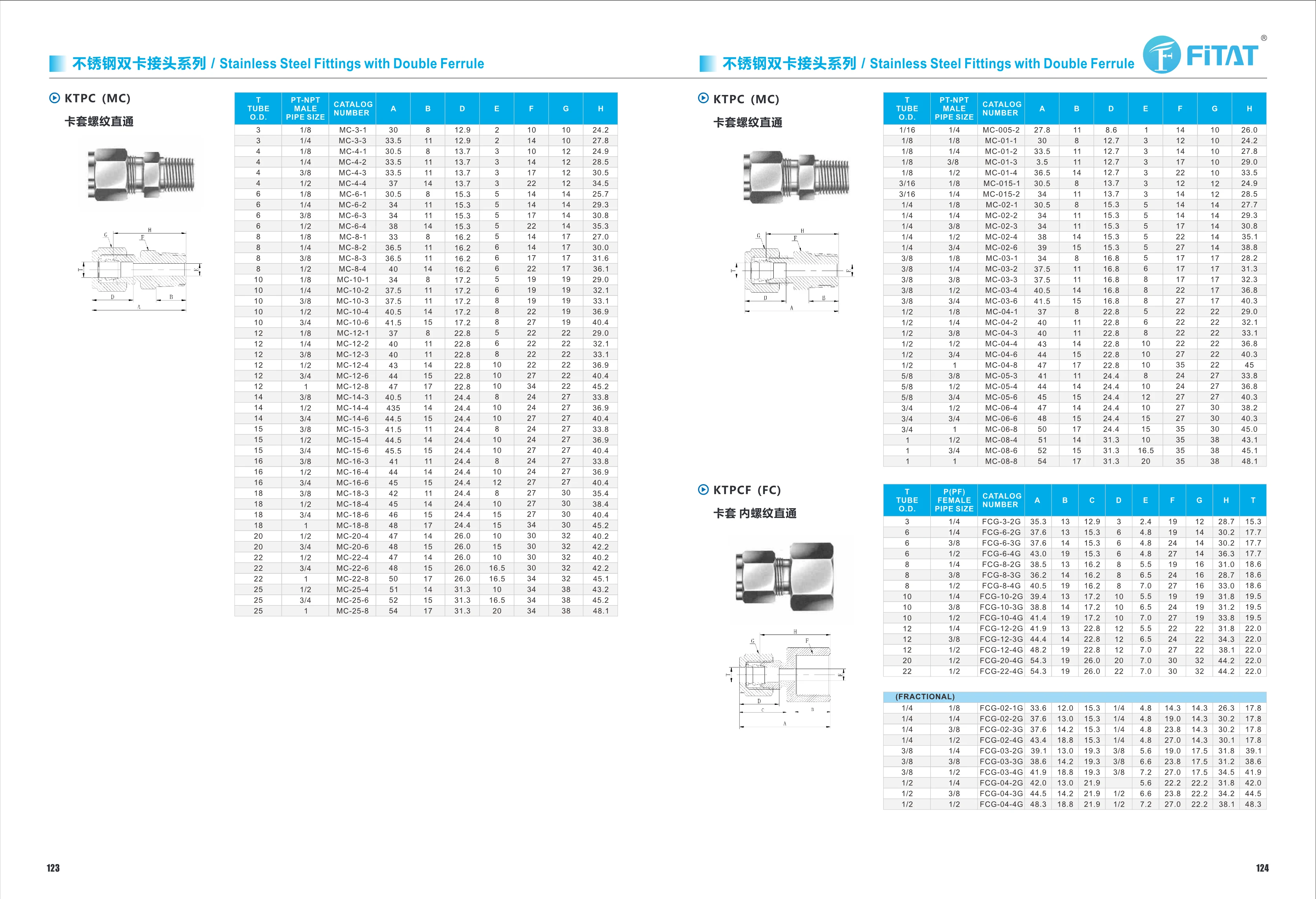
KTPC (MC) Straight Threaded Ferrule Fitting
The KTPC (MC) straight threaded ferrule fitting is part of the stainless steel twin-ferrule fitting series. Its twin-ferrule design is suitable for tubing connections in instrumentation lines, hydraulic and pneumatic systems, and automated equipment. It offers corrosion resistance, reliable sealing, and resistance to vibration and loosening. Tube outside diameters range from 3–25 mm in metric sizes and 1/16–1/2 in in imperial sizes. Thread sizes include PT/NPT 1/8–1, and various A, B, C, D, E, F, G, and H dimensions are available to accommodate different installation spaces.
KTPCF (FC) Series Female Straight Ferrule Fittings
KTPCF (FC) series stainless steel twin-ferrule female straight fittings provide a sealed tube connection without welding. They are suitable for instrumentation, hydraulic, and pneumatic lines. They accommodate metric tube outside diameters of 3~22mm and imperial sizes of 1/4~1/2in, with PT/PPT 1/8~1/2in female threads. Catalog numbers begin with FCG. The table lists overall and installation dimensions A, B, C, D, E, F, G, H, and T to assist with selection and piping design.
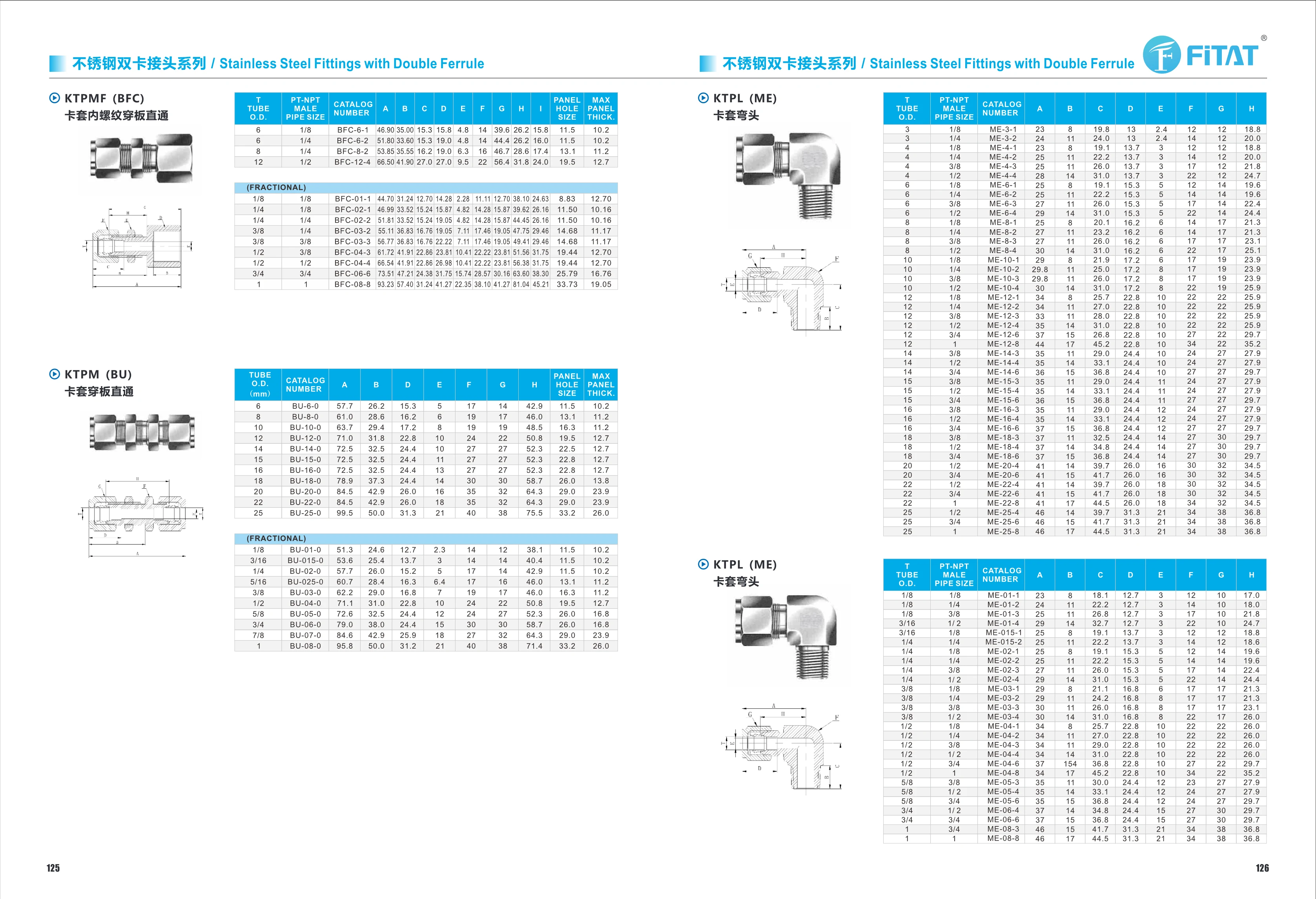
KTPM (BU) Series Ferrule Bulkhead Union
The KTPM (BU) series stainless steel double-ferrule bulkhead union provides a straight connection and secures tubing as it passes through a panel or partition. Its double-ferrule design seals reliably against the tube outer diameter, making it suitable for instrumentation, hydraulic, pneumatic and fluid lines. The catalog covers 11 sizes for tube outer diameters of 6~25 mm, with panel hole sizes of 11.5~33.2 mm and maximum panel thicknesses of 10.2~26.0 mm. Overall and installation dimensions A, B, D, E, F, G and H are provided for each size to simplify selection by panel hole and tube diameter. Made of corrosion-resistant stainless steel, it is suitable for applications requiring a connection through a panel.
KTPMF (BFC) Female Thread Ferrule Bulkhead Straight Connector
The KTPMF (BFC) is a female thread ferrule bulkhead straight connector in the stainless steel double-ferrule fitting range. Its double-ferrule sealing design uses front and rear ferrules to grip and seal the steel tube as the nut is tightened. It is suitable for panel mounting in instrumentation, pneumatic and hydraulic lines. The stainless steel body is corrosion-resistant and designed for long-term use in medium- and high-pressure applications. Sizes are classified by tube outside diameter (TUBE O.D.), with 11 sizes covering 6, 8, 10, 12, 14, 15, 16, 18, 20, 22 and 25 mm, with corresponding codes such as BU-6-0 and BU-25-0. The catalog lists the key A, B, D, E, F, G and H dimensions for each size, along with panel mounting parameters: PANEL HOLE SIZE (11.5~33.2 mm) and MAX PANEL THICK (maximum panel thickness, 10.2~26.0 mm), to aid panel hole design and nut and washer selection.
KTPL (ME) Ferrule Elbow
The KTPL (ME) ferrule elbow is part of the stainless steel twin-ferrule fitting series. It uses a twin-ferrule seal to connect tubing to a PT-NPT male threaded port at an angle in instrumentation lines, hydraulic systems, and pneumatic systems. The catalog lists a PT-NPT male thread size of 1/8 and models from ME-3 to ME-22, covering various tube outside diameter and connection combinations. Installation dimensions A–H are provided to aid selection and piping layout. The media used must be compatible with stainless steel and the ferrule seal.
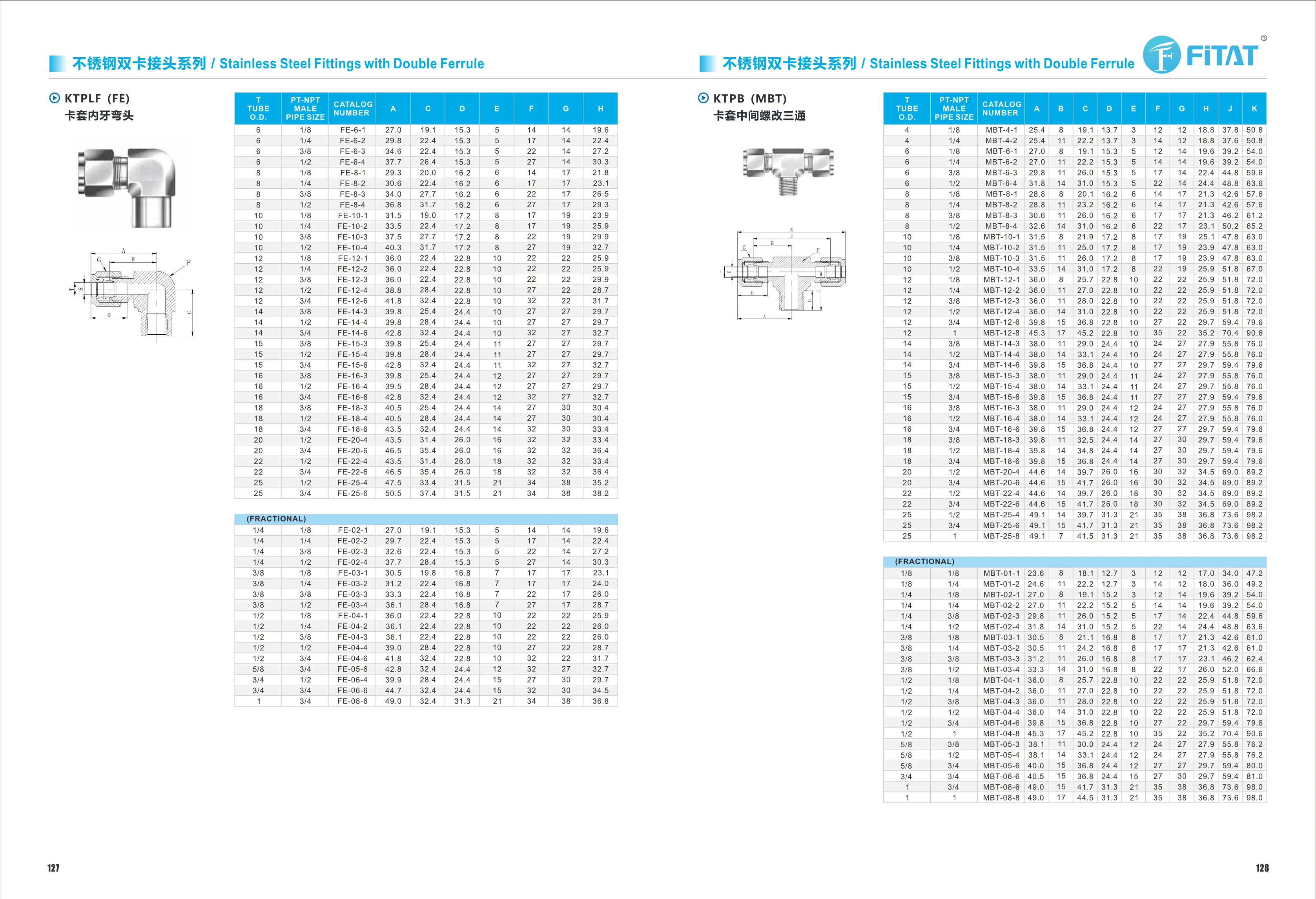
KTPLF (FE) Female Elbow Tube Fitting
The KTPLF (FE) series female elbow tube fittings are stainless steel twin-ferrule fittings designed for 90° connections between tubing and PT-NPT threaded ports in instrument lines. The catalog offers metric tube outside diameters of 6~25 mm and imperial sizes of 1/4~3/4 in, with threaded port sizes from 1/8~3/4 in. Overall and installation dimensions A, C, D, E, F, G and H are listed for each size in mm. The stainless steel body provides corrosion resistance, reliable sealing and convenient repeated assembly and disassembly. These fittings can be used in hydraulic, pneumatic, instrumentation and analytical piping systems. Order by combining the tube outside diameter code with the PT-NPT thread size code, for example FE-6-1 or FE-02-1.
KTPB (MBT) Ferrule Male Branch Tee
The KTPB (MBT) series ferrule male branch tee is a stainless steel twin-ferrule fitting used to connect a tube branch to a female threaded port. Its twin-ferrule sealing design provides high-pressure resistance, corrosion resistance and reliable sealing for instrumentation, hydraulic and gas lines. It is made of stainless steel, typically 316/304. Available tube outside diameters are 4, 6, 8 and 10mm, with PT/NPT thread sizes of 1/8, 1/4, 3/8, 1/2 and 3/4. The model code consists of the base model MBT, tube outside diameter and thread size code. For example, MBT-6-2 indicates a tube outside diameter of 6mm and a 1/4 thread. Dimensional parameters include A, B, C, D, E, F, G, H, J and K, in mm.
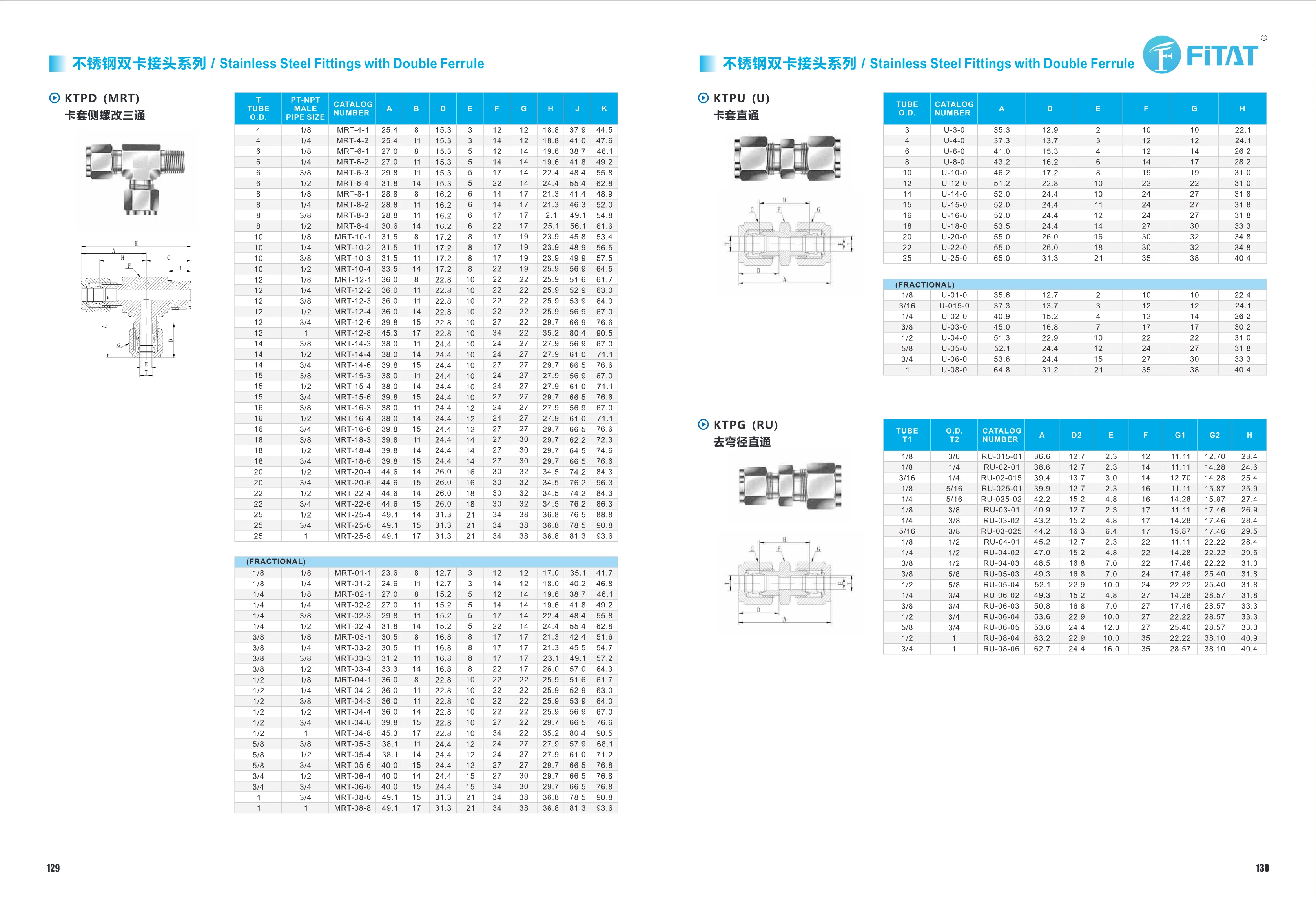
Stainless Steel Double Ferrule Fittings Series
The stainless steel double ferrule fittings series consists of 316 stainless steel tube fittings with a front and rear ferrule sealing structure. The nut compresses the ferrules, causing the tube to contract radially for a reliable seal. These fittings offer high pressure and corrosion resistance, vibration resistance, resistance to loosening, and good reassembly capability. The series covers metric and fractional tube sizes (approximately 3~40mm and 1/8"~2") and includes male straight connectors (MRT), straight unions (U), elbows and tees (UT/UE), reducing tees (UCR), weld elbows (UCR/EBW), straight weld connectors (ODBW), tube caps (C), ferrule nuts (N), front/rear ferrules (FF/BF), and check valves (KTCVC). The operating temperature is -23~190°C, and the maximum working pressure for the check valve is 414 bar(6000 psig). They are widely used in petrochemical, semiconductor, instrumentation tubing, hydraulic, and high-purity fluid applications.
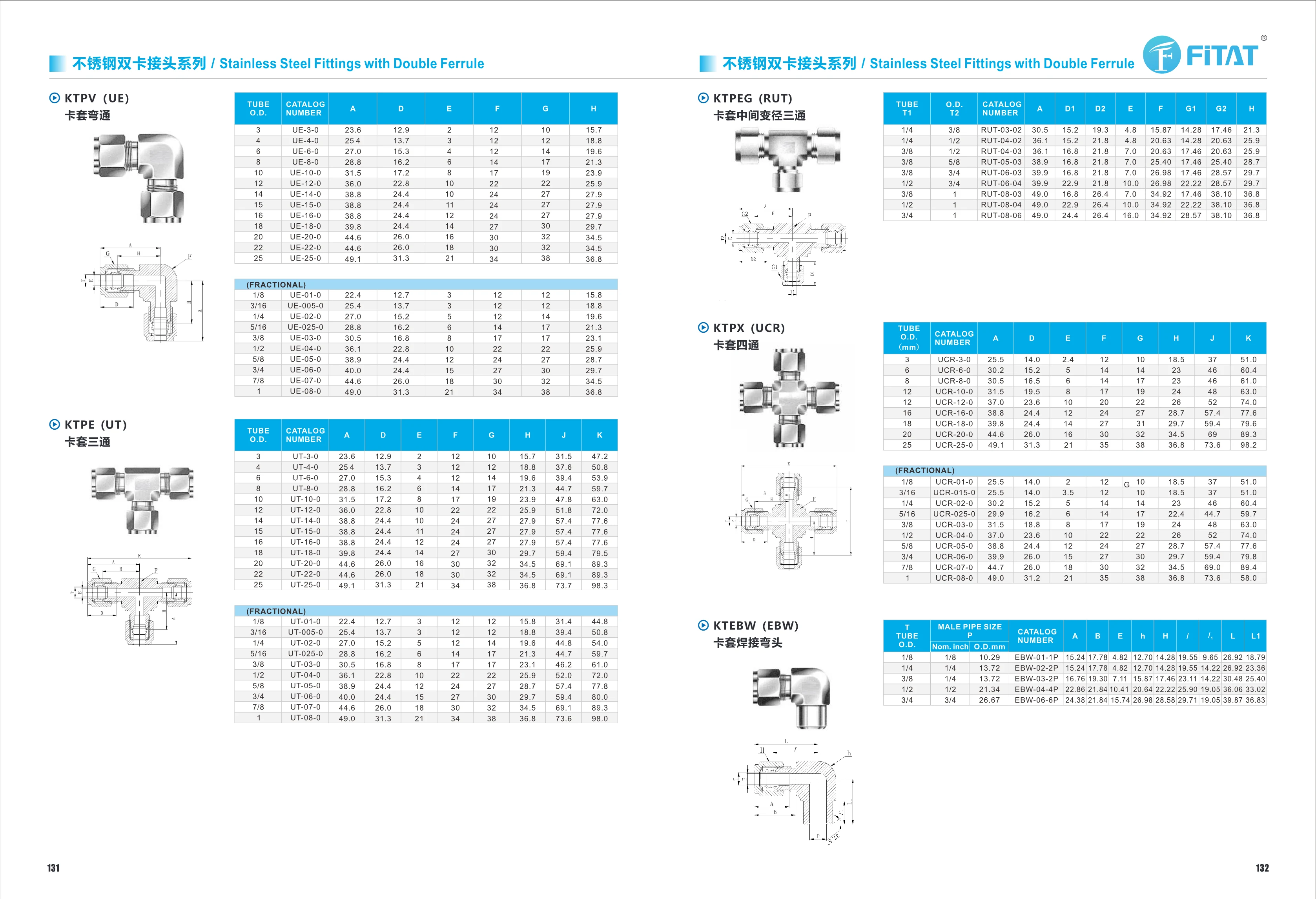
KTPV (UE) Ferrule Union Elbow
The KTPV (UE) ferrule union elbow is a 90° stainless steel double-ferrule fitting for connecting two tubes at a right angle. Its double-ferrule design uses a nut to compress the front and rear ferrules, elastically deforming the tube wall to create a seal. It requires no welding, is easy to install and remove, and resists high pressure and corrosion. It is suitable for instrumentation, fluid, pneumatic and hydraulic piping systems. Compatible tube outside diameters include 3, 4, 6, 8, 10, 12, 14, 16, 18, 20, 22 and 25mm, as well as 1 inch. The main dimensions are A, D, E, F, G, H and J (in mm). Part numbers follow the format UE/UT-tube outside diameter-variant. Common materials are 316/304 stainless steel.
KTPE (UT) Series Ferrule Tee Fittings
The KTPE (UT) series consists of twin-ferrule equal tee fittings for three-way branch connections in rigid tubing systems, including stainless steel and carbon steel tubing. The front and back ferrules grip the tube with two cutting edges to create a metal-to-metal seal. These fittings resist high pressure, vibration and temperature cycling, and can be repeatedly assembled and disassembled without welding. Common tube outside diameters include 3, 4, 6, 8, 10, 12, 14, 16, 18, 20, 22 and 25 mm, as well as 1 inch, for metric and imperial tubing. Bodies are commonly made of 316/304 stainless steel, with brass and carbon steel versions also available. The catalog lists overall and installation dimensions A, D, E, F, G, H, J and K for each tube outside diameter to facilitate tubing design and clearance checks. Suitable media include oil, water, gas and generally corrosive fluids. Applications include semiconductor equipment, analytical instruments, hydraulic and pneumatic systems, petrochemical installations, and food and pharmaceutical processing lines. Select the model according to tube outside diameter, such as UE-6-0 or UE-8-0, and confirm the thread specification and material as required.
KTPEG (RUT) Ferrule Branch-Reducing Union Tee
KTPEG (RUT) series branch-reducing union tees feature a twin-ferrule design for connecting stainless steel tubing and offer high-pressure and corrosion resistance. Available for tube outside diameters from 1/4 inch to 1 inch or 25mm, their reducing design connects tubing of different sizes. The twin-ferrule design provides a reliable seal and allows easy installation without welding. They are widely used in instrumentation tubing systems in the petroleum, chemical, power generation, and water treatment industries. Dimensional parameters include A, D1, D2, E, F, G1, G2, and H to ensure a precise fit.
KTPEW (UBW) Ferrule Weld Elbow
The KTPEW (UBW) ferrule weld elbow is part of a stainless steel double-ferrule fitting series, designed for right-angle turns and welded connections in instrumentation tubing. Its double-ferrule sealing design fits metal tubing with outside diameters of 1/8–1 inch. The weld-end elbow maintains a seal under high pressure, vibration, and temperature fluctuations. The catalog provides dimensions A, B, E, H, I, and L1 for layout and installation. Made of stainless steel, it is suitable for piping requiring corrosion resistance in petrochemical, instrumentation, hydraulic, and pneumatic systems. Catalog numbers range from UCR-01-0 to UCR-08-0 according to tube outside diameter.
KTEBW (EBW) Ferrule-to-Weld Elbow
KTEBW (EBW) series ferrule-to-weld elbows are stainless steel twin-ferrule fittings that connect tubing to welded steel pipe with a 90° change in direction. The twin-ferrule sealing design connects to tubing at one end and has a weld connection at the other, allowing the tube end to be sealed without welding. Ten sizes are available for tube outside diameters from 1/8″ to 1″. Typically made of 316/304 stainless steel, they offer pressure and corrosion resistance for instrumentation lines, hydraulic and pneumatic systems, and high-purity piping. Select the fitting to match the tube outside diameter and connection size. Note: The catalog numbers in the catalog table are listed as UCR-xx-x, which differs from the EBW series designation. They are reproduced here as originally listed.
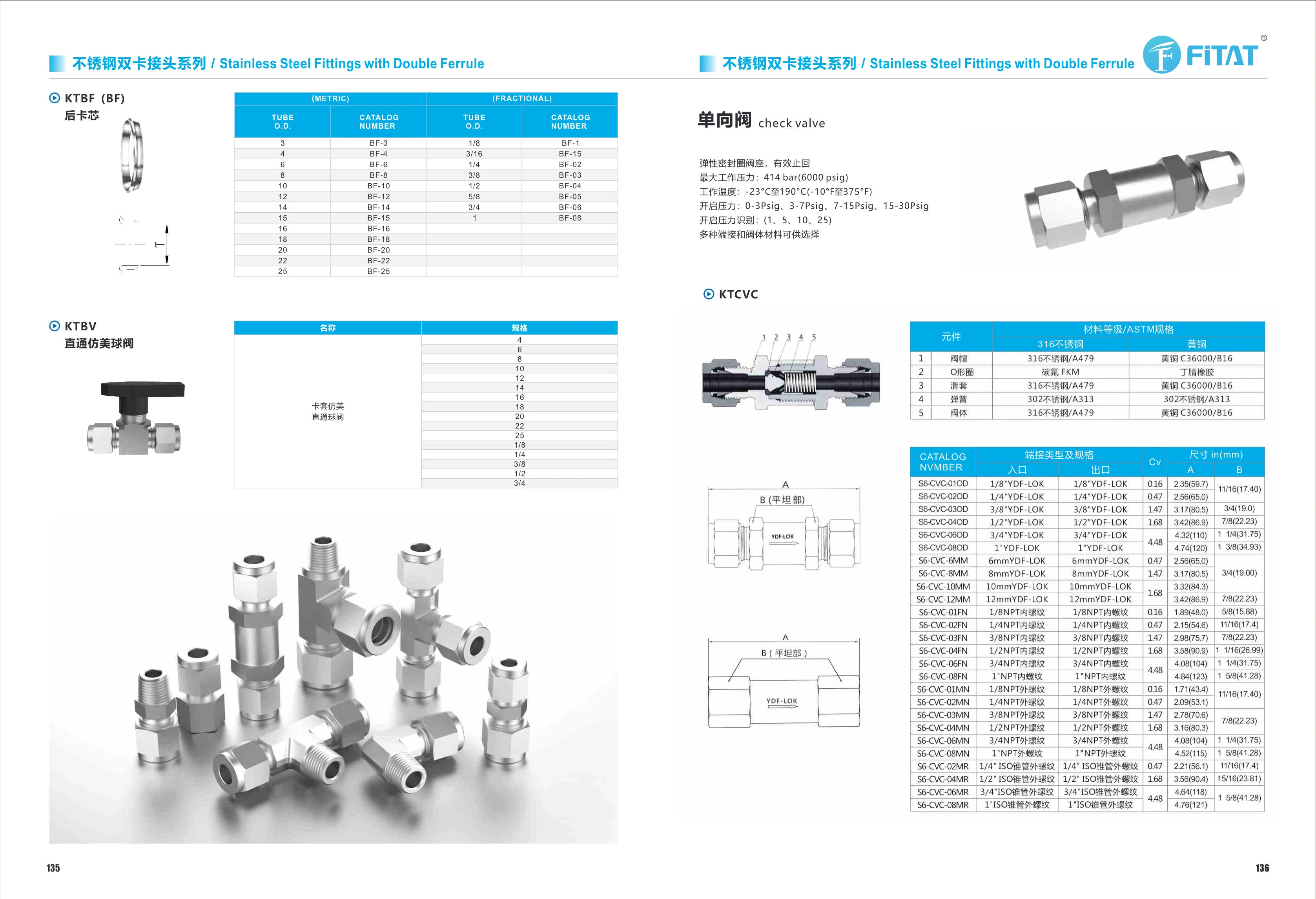
KTCVC Series Check Valves
KTCVC series check valves use a resilient seal seat to provide reliable one-way flow and prevent backflow in piping systems. Maximum working pressure is 414 bar (6000 psig), and operating temperature ranges from -23°C to 190°C (-10°F to 375°F). Bodies are available in 316 stainless steel (ASTM A479) or brass (C36000/B16). The bonnet and sleeve are made of the same material as the body, and the spring is 302 stainless steel (A313). O-rings are fluorocarbon FKM for 316 stainless steel bodies and nitrile rubber for brass bodies. Four cracking pressure ranges are available: 0-3, 3-7, 7-15 and 15-30 psig, corresponding to identification numbers 1, 5, 10 and 25. YDF-LOK double-ferrule end connections are available in imperial sizes from 1/8 to 1 inch and metric sizes from 6 to 32 mm. CV values range from 0.16 to 4.48, with a choice of end connections and body materials.
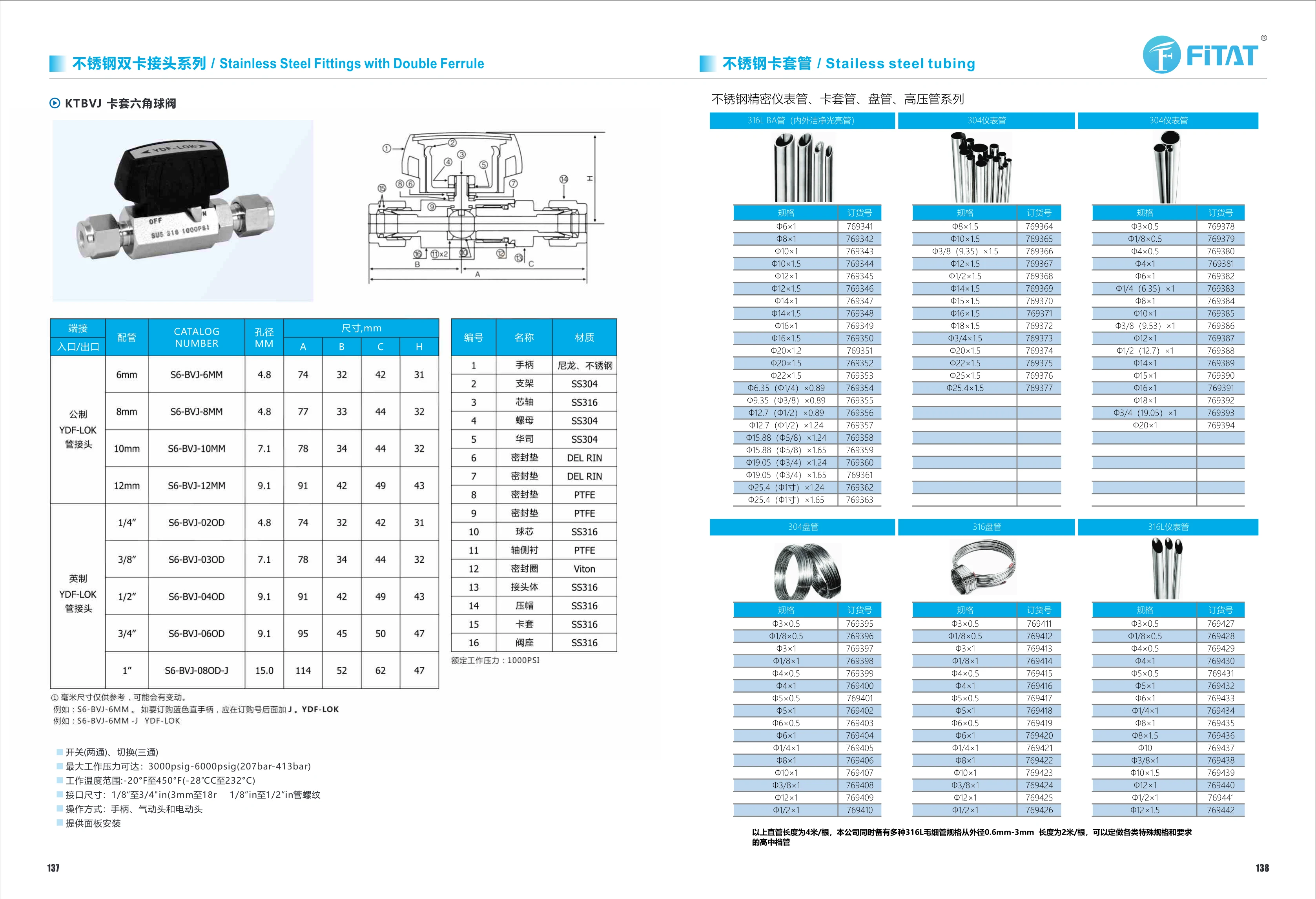
KTBVJ Series Hexagonal Ferrule Ball Valve
The KTBVJ series hexagonal ferrule ball valve is a stainless steel instrumentation valve with twin-ferrule fittings. Its hexagonal body connects to tubing via twin ferrules for on/off control of media in automation equipment, instrumentation lines, and fluid systems. The catalog lists metric tubing sizes from Φ3×0.5 to Φ20×1, as well as imperial and mixed sizes such as Φ1/8×0.5 and Φ3/4(19.05)×1, with corresponding order numbers 769378~769394. When selecting a valve, verify the tubing outside diameter, wall thickness, and end connection type. During installation, tighten in accordance with twin-ferrule fitting specifications to ensure a leak-tight seal.
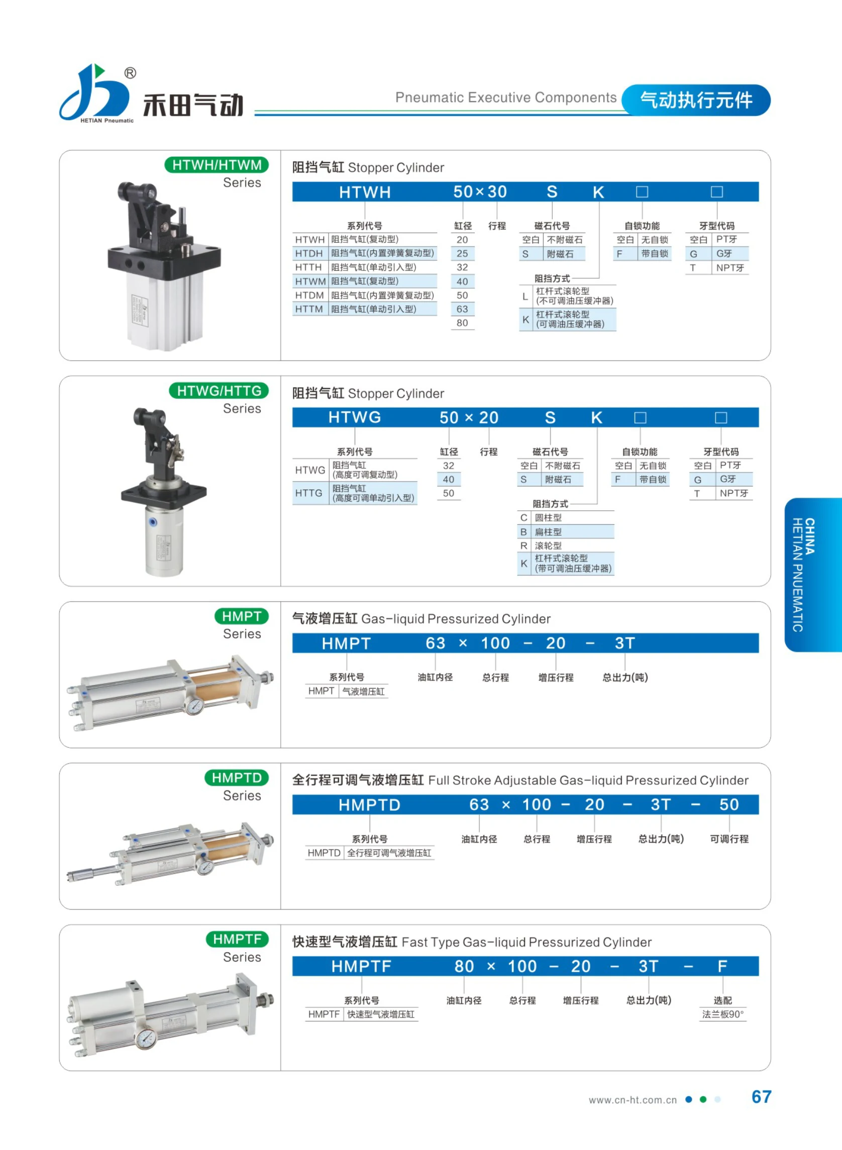
HMPT Series Air-Hydraulic Booster Cylinders
The HMPT series air-hydraulic booster cylinder is a pneumatic actuator that converts and intensifies low-pressure compressed air to drive a hydraulic cylinder. It combines the fast action of a pneumatic cylinder with the high force of a hydraulic cylinder, making it suitable for stamping, riveting, press fitting, bending, shearing, and other applications requiring high momentary force. The model code consists of the series designation HMPT, cylinder bore, total stroke, boost stroke, total output force (tons), and adjustable stroke or option code. For example, HMPT 63×100-20-3T 50 indicates a 63mm cylinder bore, 100mm total stroke, 20mm boost stroke, 3-ton total output force, and 50mm adjustable stroke. The suffix option code F indicates a fast-type air-hydraulic booster cylinder.
HMPT Series High-Speed Air-Oil Booster Cylinders
An air-oil booster cylinder is an actuator that converts low-pressure compressed air into high-pressure hydraulic output through a booster. It combines the fast action of a pneumatic cylinder with the high force of a hydraulic cylinder and is widely used for press-fitting, riveting, stamping, bending and cutting. The HMPT series comprises high-speed air-oil booster cylinders. Specifications are expressed as “hydraulic cylinder bore×total stroke-boost stroke-total output force (tons).” For example, 63×100-20-3T indicates a hydraulic cylinder bore of 63mm, a total stroke of 100mm, a boost stroke of 20mm and a total output force of 3 tons; 80×100-20-3T indicates a hydraulic cylinder bore of 80mm, a total stroke of 100mm, a boost stroke of 20mm and a total output force of 3 tons. Common specifications include hydraulic cylinder bores of 63 and 80mm, a total stroke of 100mm, a boost stroke of 20mm and a total output force of 3T. An adjustable stroke (such as 50mm) can be added to the standard type, while option F is available for the high-speed type. Select the output tonnage according to the press-fitting force required by the workpiece, and determine the total stroke and boost stroke according to the available working space and stroke requirements.

MOB Series Hydraulic Cylinders
The MOB series is a standard hydraulic cylinder manufactured by Shansi Automation (Ningbo) Group Co., Ltd., with MOB as the type designation. Bore diameters include Φ30, Φ40, Φ50, Φ63, Φ80, Φ100, Φ125, Φ160, and Φ200, and the stroke can be specified to suit user requirements. Cylinder mounting options include FA front flange, TC intermediate trunnion, and TC-M configurations. The rod-end mounting type is a Y-type clevis, which can be used with an ISO-PHS rod-end bearing for pivoting connections. Rod thread types are H or E (external thread, unmarked). A magnet (M) and cushioning positions (2/R) are optional. The catalog provides overall and mounting dimensions such as EB, EC, ED, EE, EG, EP, ET, and S for each bore size, as well as detailed dimensions including HA~HP for the TC-M type and PA~PH and NA~PB for the ISO-PHS rod-end bearing and Y-type clevis. These dimensions facilitate selection by bore and stroke and verification of installation space.
Y-Type Clevis
A Y-type clevis is a forked pivoting attachment fitted to the end of a pneumatic or hydraulic cylinder piston rod. It connects the rod to a load or oscillating mechanism, allowing angular movement while supporting tensile and compressive loads. The catalog provides dimensional series for cylinder bores of 32, 40, 50, 63, 80, 100, 125, 160, and 200 mm, including dimensions and thread specifications such as PA/PB/PC/PD/PE/PF/PG/PH and NA/NB/NC/NE/NF/NG/NH/NJ/NK/NM/MP/NQ/PA/PB. Threads range from M10×1.25 to M36×2. Select according to cylinder bore and available mounting space.
HOB Series Square Heavy-Duty Integral-Body Hydraulic Cylinder
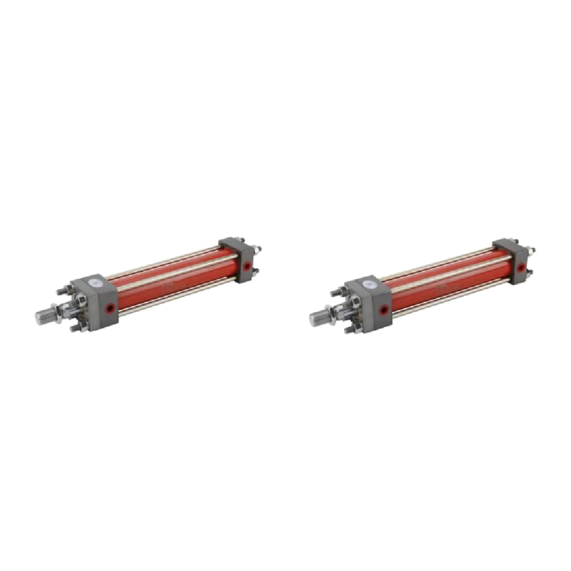
The HOB series heavy-duty hydraulic cylinder features a square cylinder body with an integral-body construction. It is designed for high-pressure, heavy-load hydraulic applications such as stamping, injection molding, construction machinery, and automated equipment. Bore sizes include Φ40, Φ50, Φ63, Φ80, Φ100, Φ125, Φ150, Φ180, and Φ200, with custom strokes available. Cylinder mounting options include front flange (FA), while piston rod end options include 10A and Y. A magnet and cushioning at position R are standard. Cylinder bore and rod dimensions correspond to the standard specification table. The A-mount steel sleeve can be extended 5mm beyond the body for easier installation and adjustment.

ROB Series Hydraulic Cylinders
The ROB series hydraulic cylinders are hydraulic actuators from Shansi Automation (Ningbo) Group Co., Ltd., designed for linear push-pull, clamping, and ejection operations in molds, machine tools, fixtures, and automation equipment. Cylinder bore and stroke are the primary selection parameters. The piston rod thread is available in five sizes: M8×1.25, M10×1.25, M14×1.25, M16×1.25, and M22×1.25. Different rod-end and mounting accessory configurations accommodate a range of installation methods, including flanges and clevises. When ordering, specify the model, rod thread type, cylinder bore, stroke, rod-end mounting type, and mounting accessory type in that order, as indicated in the model designation, to ensure compatibility between the cylinder body, rod-end thread, and mounting interface. Wrench clearance dimensions A, B, C, D, E, J, H, and R for the corresponding threads are specified by cylinder bore to facilitate installation and maintenance.