Mechanical Standard Parts — Page 2
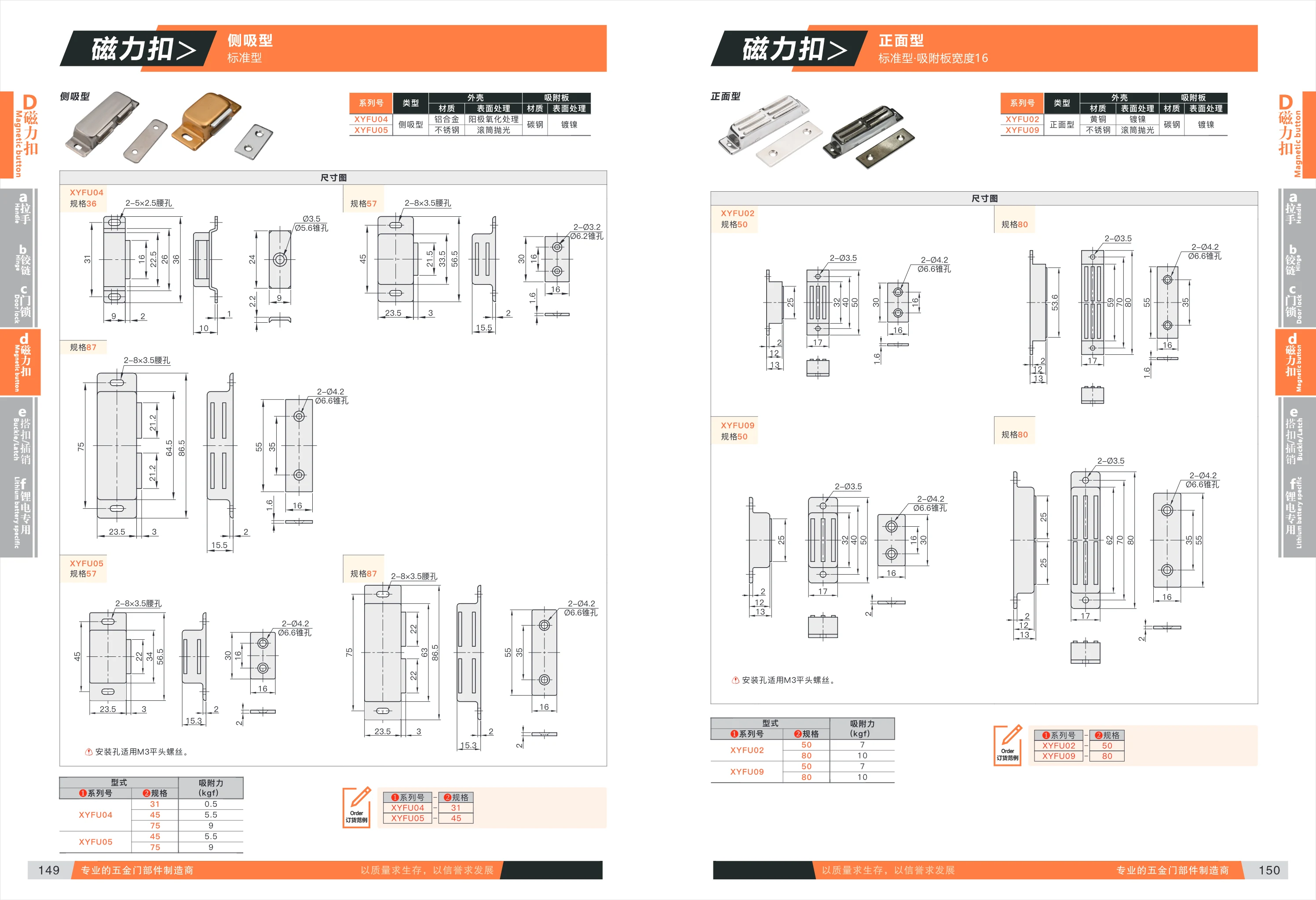
XYFU Series Magnetic Holding Products
The XYFU series comprises magnetic holding products for automation components. It includes models such as XYFU02, XYFU04, XYFU05, and XYFU09, each available in different sizes (such as 31, 45, and 75) and with different holding forces (kgf). These products are suitable for applications such as gripping and positioning in industrial automation.
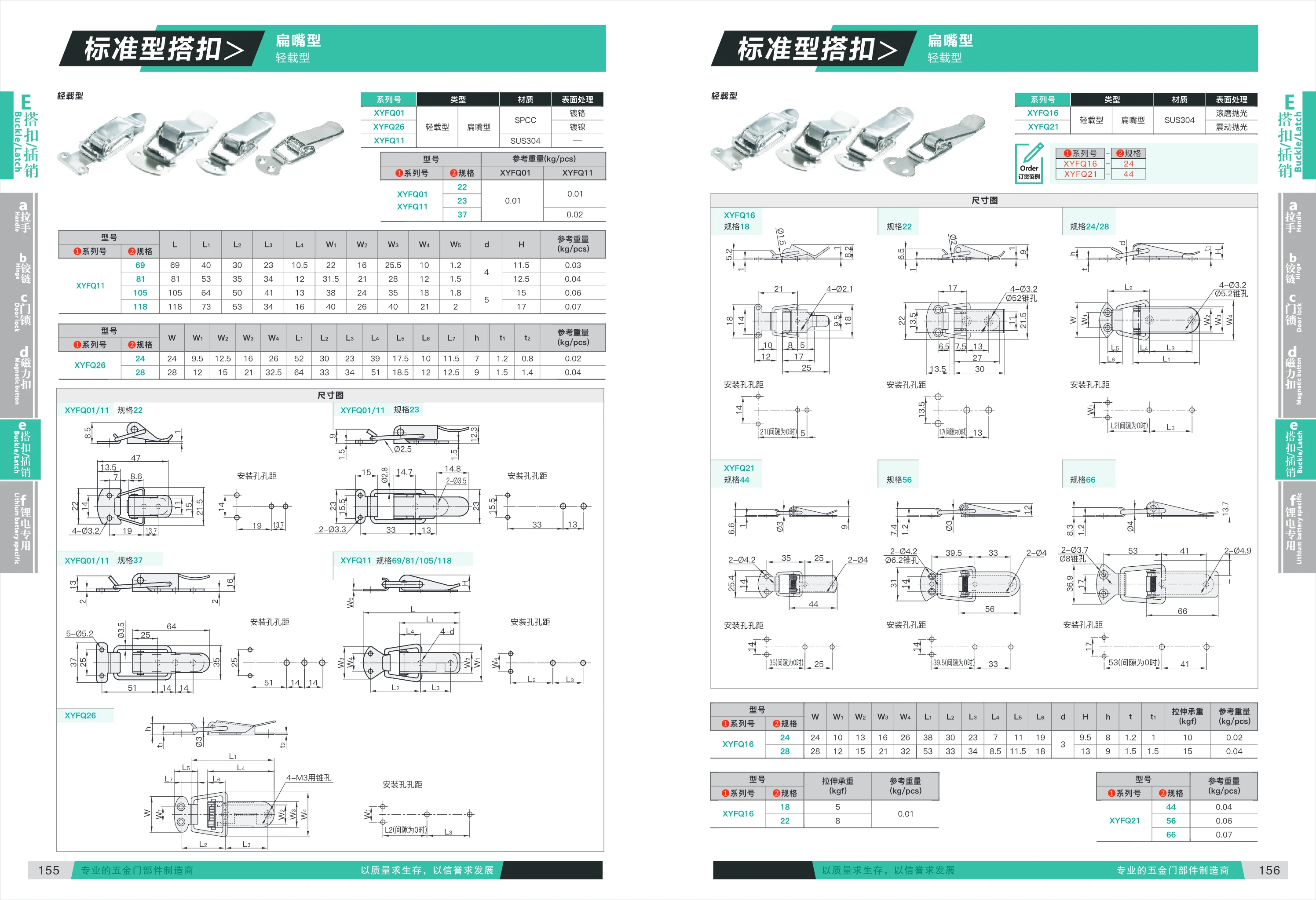
XYFQ Series Mechanical Components
The XYFQ series includes mechanical components made from a range of materials, including light-duty models (chrome-plated SPCC), stainless steel models (SUS304), and retaining rings (XYFQ31/41/46). Designed for mechanical connections, fastening, and locking applications, these components are available in a variety of sizes to meet different load requirements. The reference weight is 0.01 kg/pc for light-duty models and 0.02 kg/pc for stainless steel models. Retaining ring products include detailed installation dimensions; tensile loads are calculated based on a 1 mm interference fit when fastened.
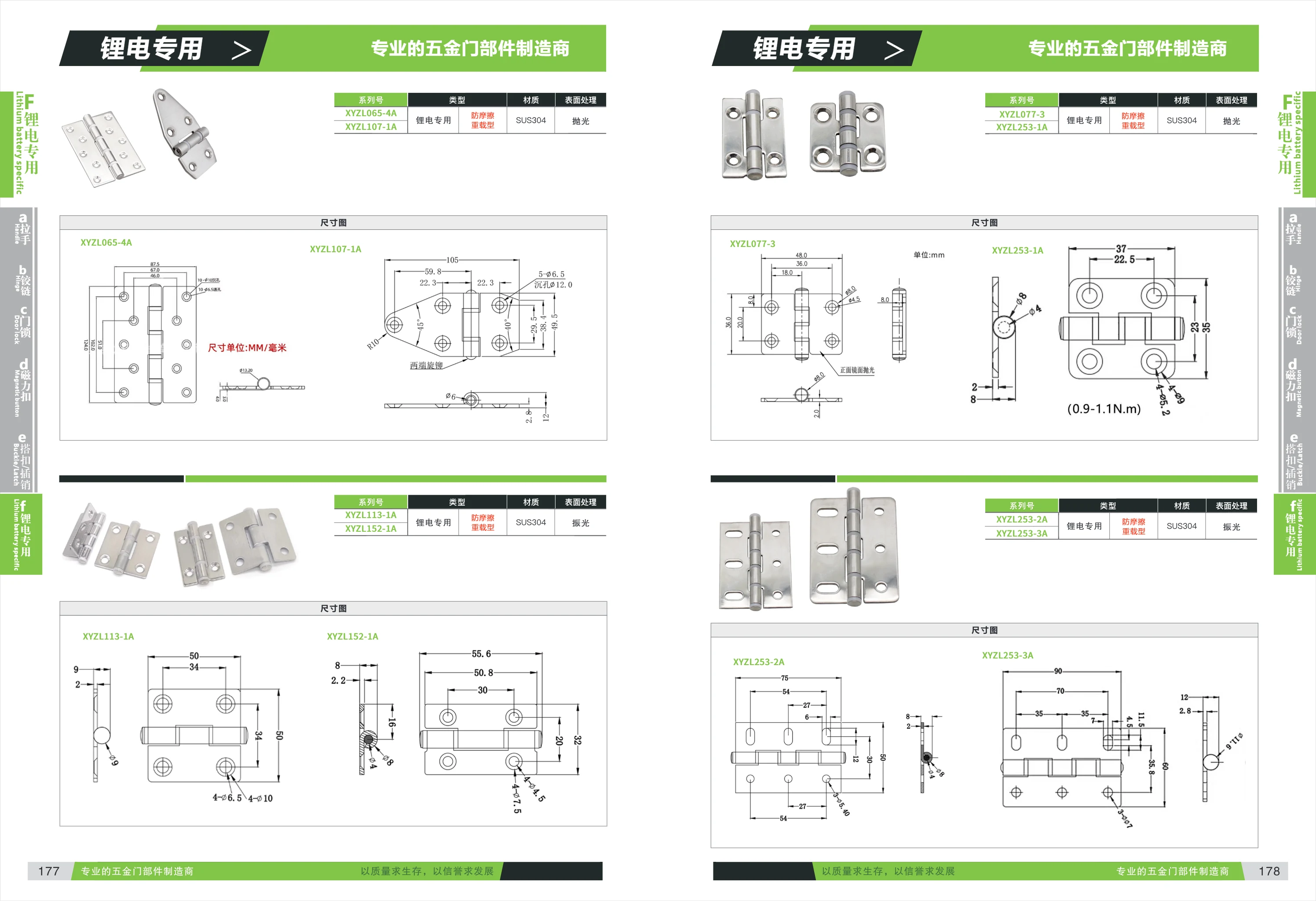
XYZL Series Anti-Friction Type for Lithium Battery Equipment
XYZL series anti-friction components for lithium battery equipment are designed specifically for lithium battery manufacturing machinery. Made of SUS304 stainless steel, they feature a SUS304 surface finish. The series includes loaded and non-loaded types, with a range of specifications such as XYZL065-4A, XYZL077-3, XYZL253-1A, XYZL253-2A, and XYZL253-3A to suit different installation requirements. With anti-friction properties, these products are suitable for applications with strict requirements for friction and wear, helping ensure long-term, stable equipment operation.
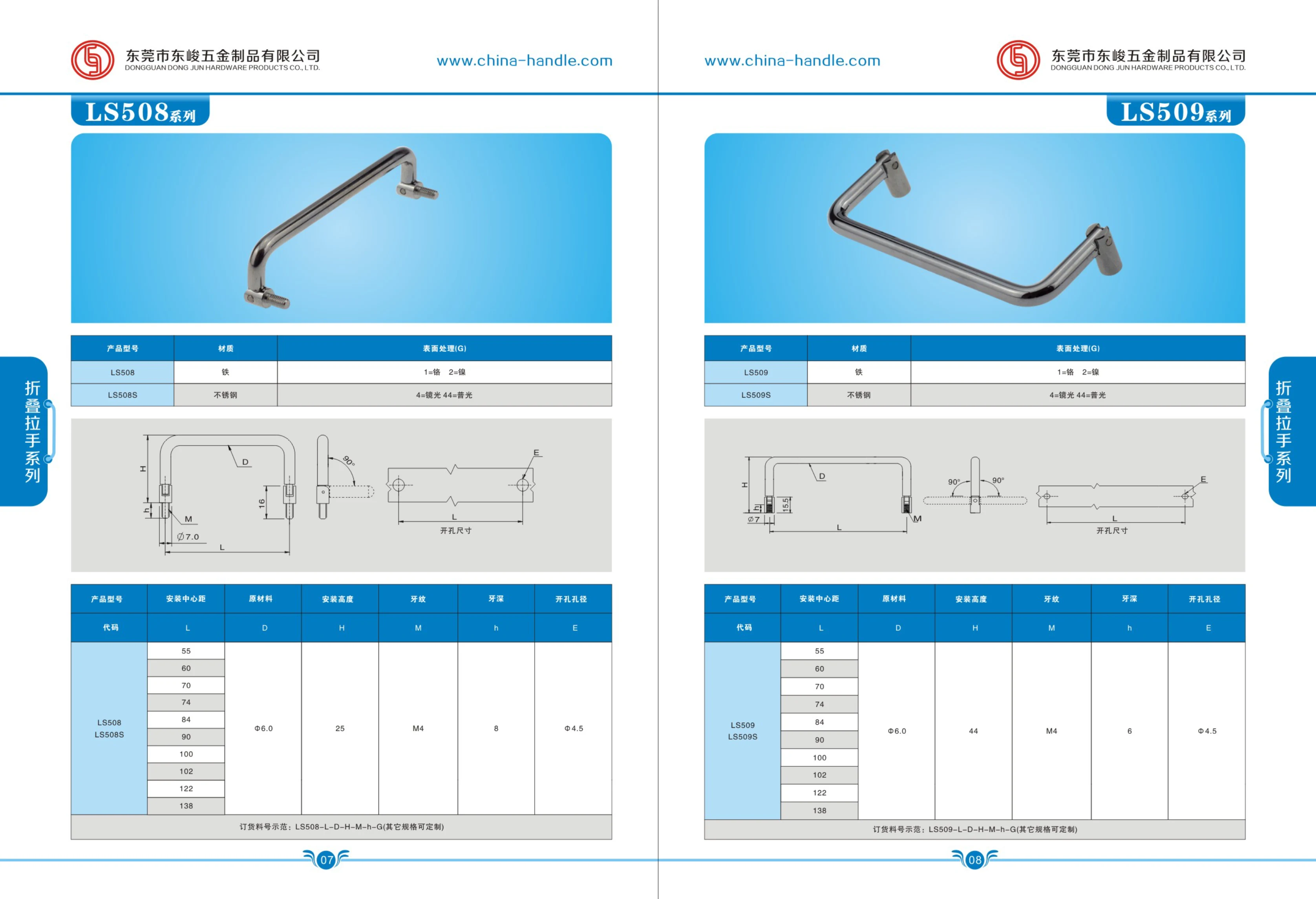
LS Series
LS Series mounting bases are available in four models: LS508, LS508S, LS509, and LS509S. Materials include iron and stainless steel. Surface finishes include chrome (1), nickel (2), bright plating (4), and standard bright finish (44). The LS509 series offers several mounting center distances (55–138 mm), a fixed-part material diameter of Φ6.0, a mounting height of 44 mm, an M4 thread, a thread depth of 6 mm, and a hole diameter of Φ4.5 mm. Other specifications can be customized.
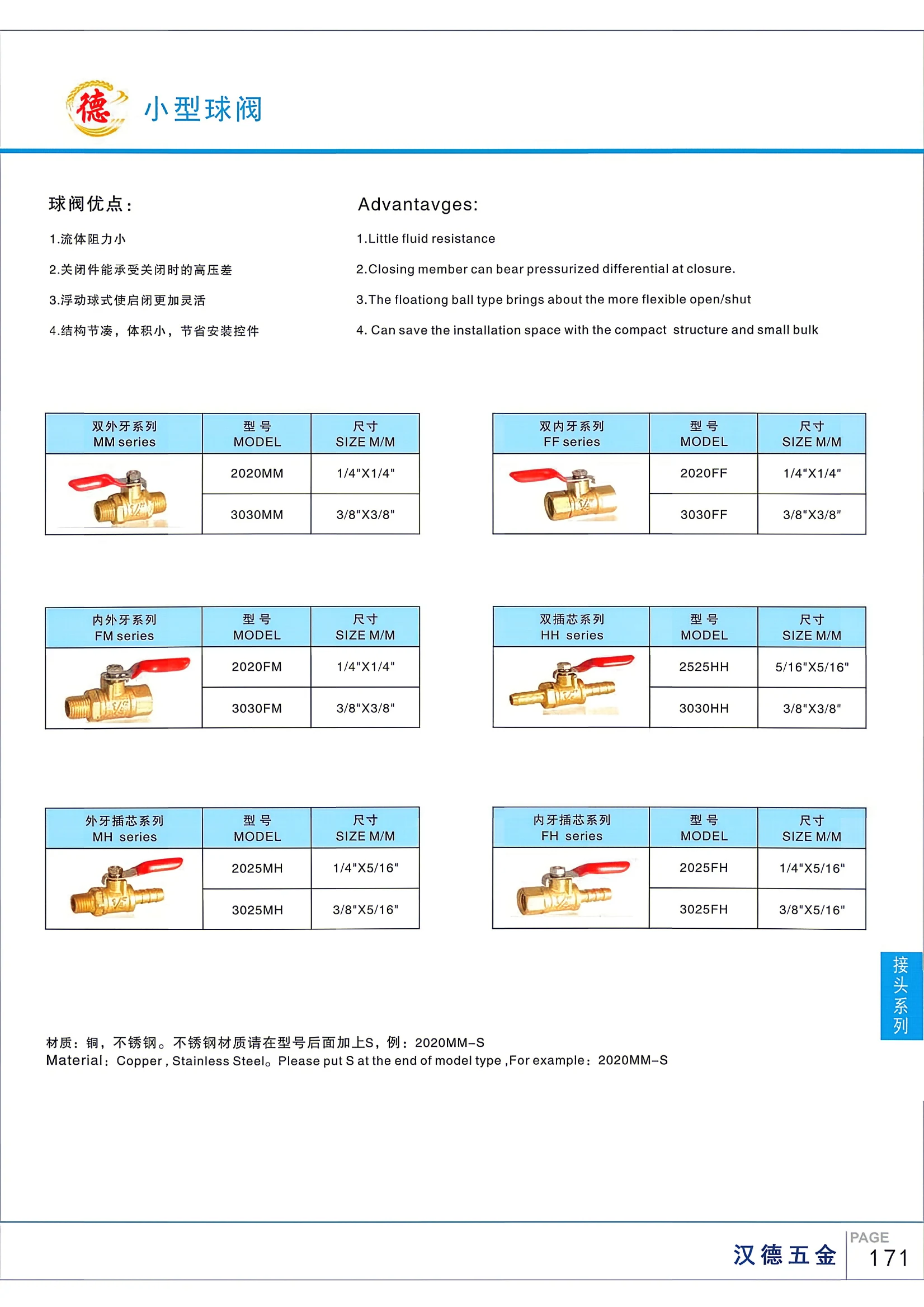
Ball Valve Series
The ball valve series is made of brass or stainless steel and features low fluid resistance, smooth opening and closing, and a compact design. Products are available with various connection types, including double male (MM), double female (FF), and male-female (MF/FM), as well as special models such as full-bore high-temperature valves (up to 280°C) and butterfly-handle valves. Working pressure: 1.6–3.0 MPa. Working temperature: -20°C to 100°C (up to 280°C for high-temperature models). Suitable for water and other non-corrosive liquids. Threads comply with ISO 228.
Double Male Thread Series MM Series
Double Male Thread Series MM Series ball valves feature a floating-ball design for smooth operation and a compact, space-saving structure. They offer low flow resistance, and the closure element can withstand high differential pressure. Available in brass and stainless steel; add S to the model number for stainless steel, for example, 2020MM-S. Common sizes include the 2020 series (1/4" x 1/4") and the 3030 series, suitable for a variety of pipe connections.
FM Series Male/Female Threaded Ball Valves
FM series ball valves feature a floating-ball design for smooth operation, low flow resistance, and reliable shutoff under high differential pressure. Their compact construction saves installation space. Available in brass and stainless steel; stainless steel models have an “S” suffix. A range of size and thread combinations is available, including 1/4" × 1/4" and 1/4" × 5/16", making them suitable for industrial piping systems.
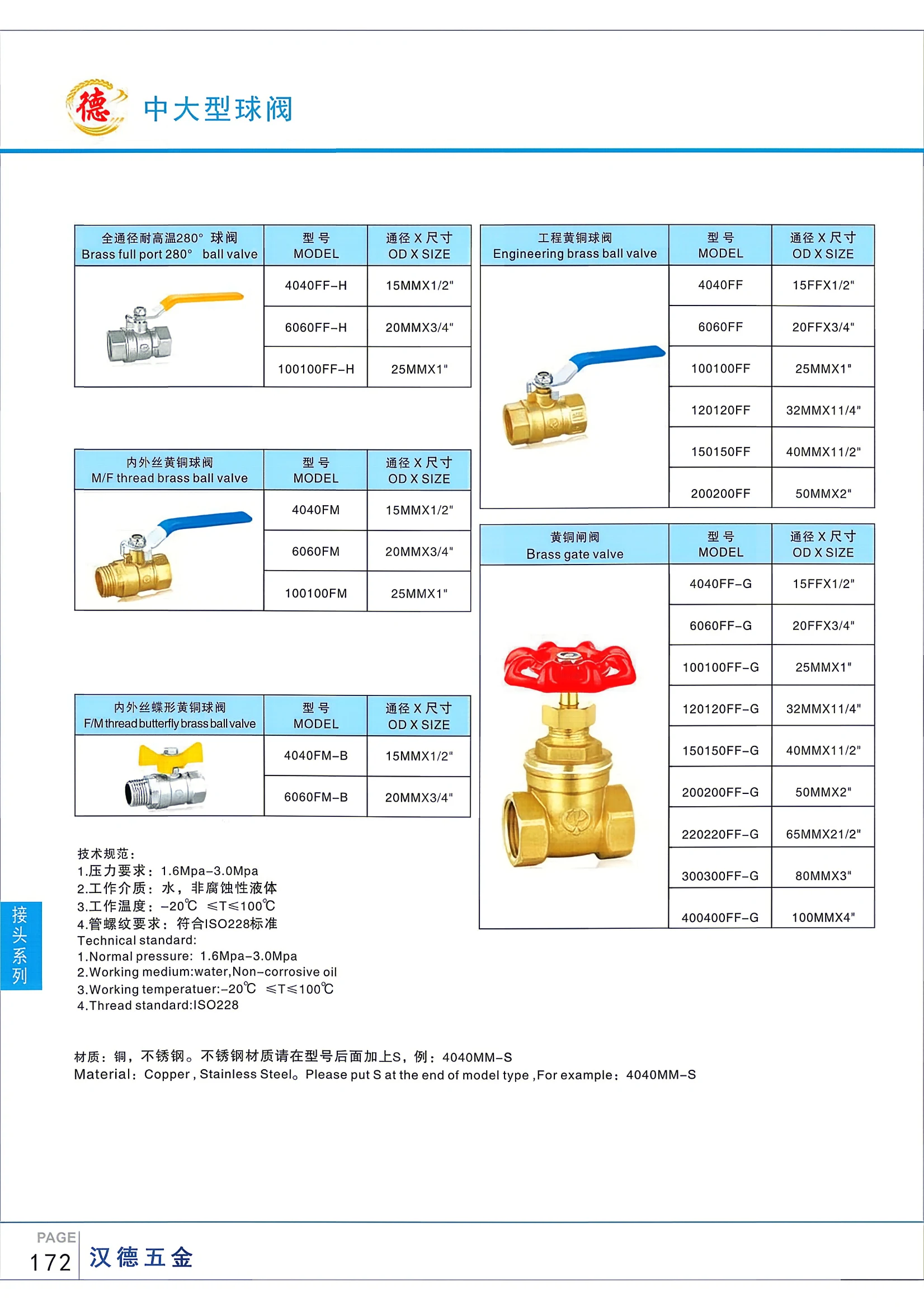
Full-Bore Ball Valve, Heat-Resistant to 280°
The full-bore, heat-resistant-to-280° ball valve series includes engineering brass ball valves, male-female brass ball valves, male-female butterfly-handle brass ball valves, and other types. Made of brass (stainless steel available on request; add S to the model number). Pressure range: 1.6–3.0 MPa. Operating temperature: −20°C to 100°C. Pipe threads comply with ISO 228. Bore sizes range from 15 mm to 50 mm, with corresponding thread sizes from 1/2" to 2".
Engineering Brass Ball Valves
The engineering brass ball valve series includes a range of types, such as full-bore ball valves rated for temperatures up to 280°, female-to-male threaded brass ball valves, and female-to-male threaded brass ball valves with butterfly handles. Made of brass or stainless steel (stainless steel models carry the suffix S), the valves are rated for pressures of 1.6–3.0 MPa and operating temperatures from −20°C to 100°C. Pipe threads conform to ISO 228. Nominal diameters range from 15 mm to 50 mm, with connection thread sizes from 1/2" to 2". Suitable for water and other non-corrosive liquids.
Brass Ball Valve Series
This series of brass ball valves includes several types, such as full-bore ball valves rated for high temperatures up to 280°, industrial brass ball valves, brass ball valves with female and male threaded ends, and butterfly-handle brass ball valves with female and male threaded ends. Operating pressure: 1.6–3.0 MPa. Suitable media: water or non-corrosive liquids. Operating temperature: −20°C to 100°C. Pipe threads comply with ISO 228. Available in brass and stainless steel (stainless steel models carry the suffix S). Models include 4040FF-H (15MMX1/2") and 4040FF (15FFX1/2"), among others, in a range of nominal bore sizes.
Female-to-male threaded brass ball valve with butterfly handle
Female-to-male threaded brass ball valve with butterfly handle, made of brass (stainless steel optional), for water and non-corrosive liquids. Working pressure: 1.6–3.0 MPa; working temperature: −20°C to 100°C. Pipe threads comply with ISO 228. The suffix -S in the model number indicates stainless steel.
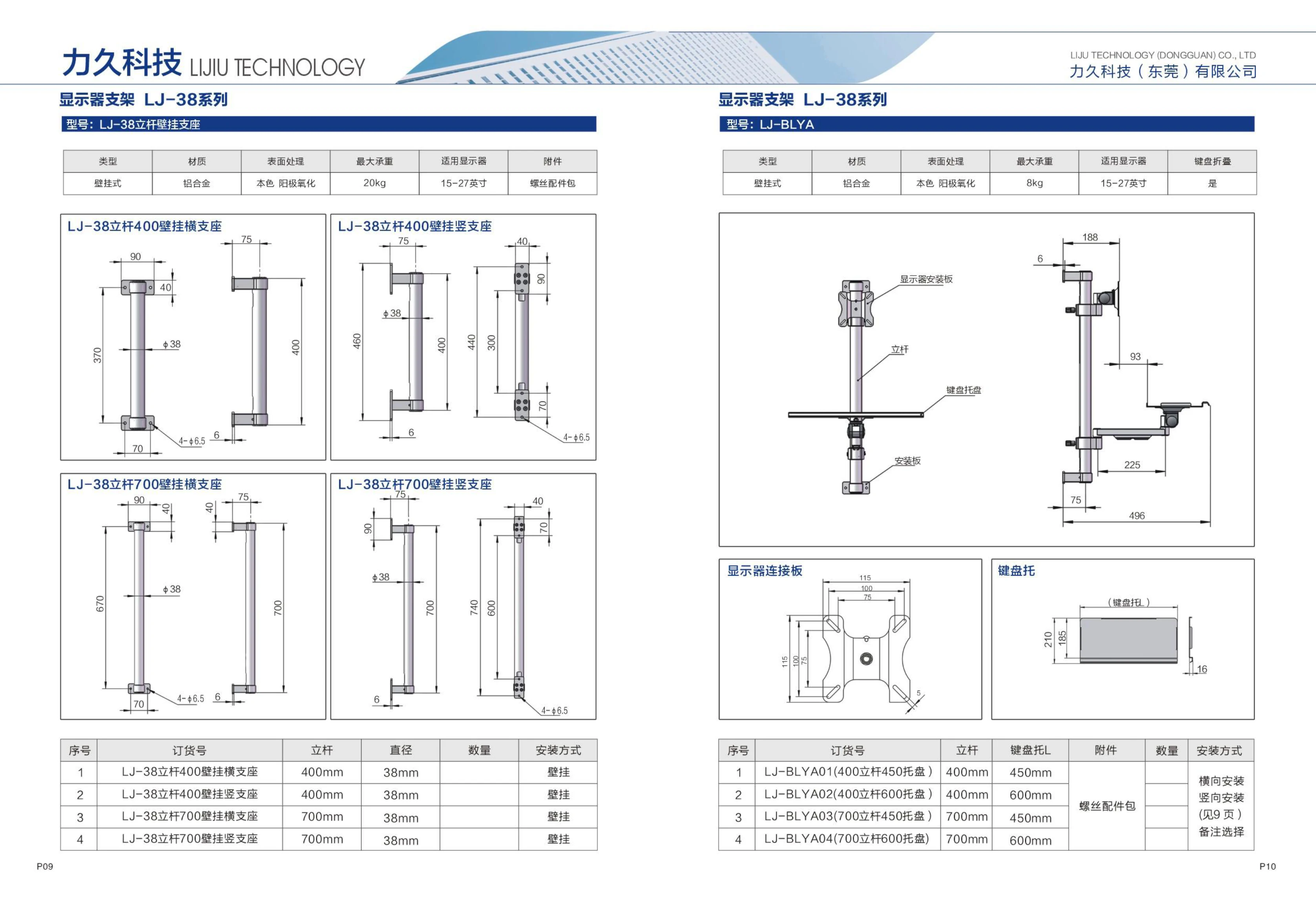
LJ Series Support Posts
LJ Series support posts are support components for industrial automation and office equipment. The posts have a diameter of 38 mm and are available in lengths of 400 mm or 700 mm. They can be installed with a horizontal or vertical wall-mount bracket, or paired with a keyboard tray (LJ-BLYA models). Keyboard trays are available in lengths of 450 mm and 600 mm. A screw accessory kit is included. Suitable for machines, workstations and other applications, these posts offer flexible mounting options.
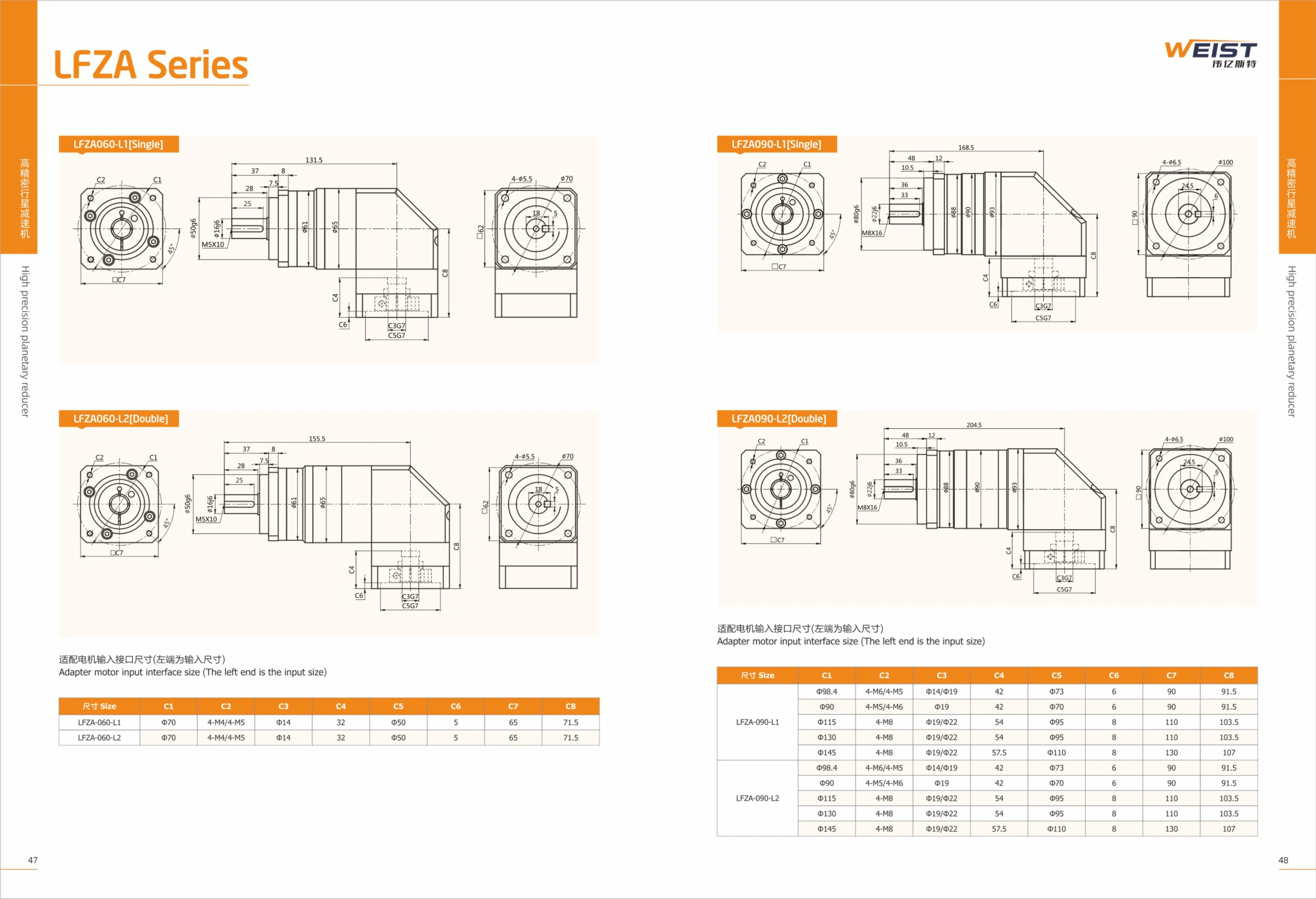
LFZA Series Motor Input Interface Adapter
The LFZA series adapters are designed for servo motor input interfaces. They are available in several sizes (060/090/115/140/180) and two mounting configurations: single slide (L1) and dual slide (L2). The C1–C8 dimensional parameter table lists the motor interface dimensions compatible with each model, including key measurements such as mounting hole spacing, center hole diameter, and flange outer diameter. The adapters suit a range of motor interface standards, including center holes from Φ14 to Φ42 and threaded holes from M4 to M12.
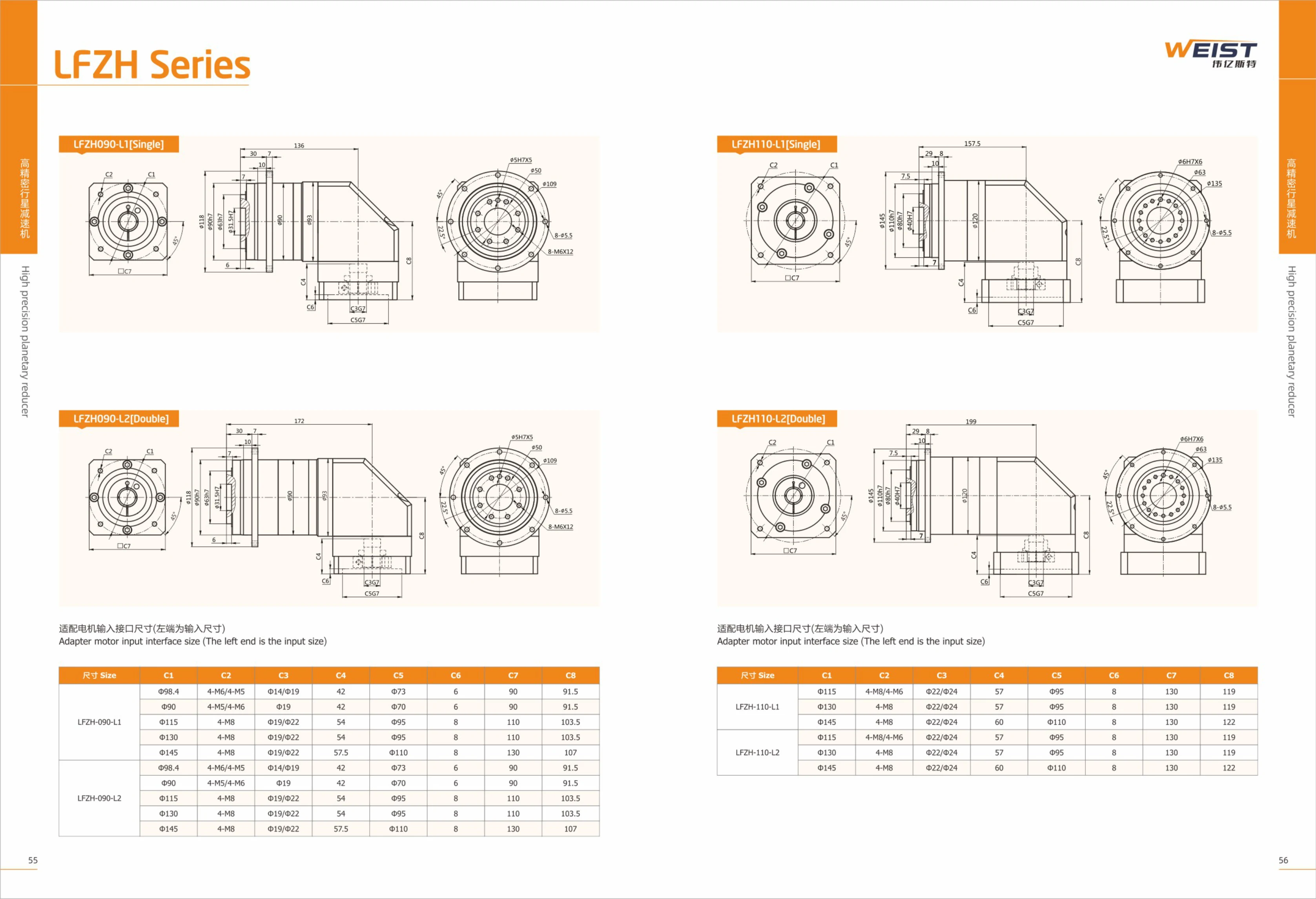
LFZH Series Motor Input Interface Adapters
LFZH Series Motor Input Interface Adapters connect motors to mechanical equipment. Available in single-stage (L1) and double-stage (L2) versions to suit different installation requirements, the range includes four basic models: LFZH090, LFZH110, LFZH140, and LFZH200. Each model offers a variety of flange interface combinations (sizes C1–C8) to accommodate different motor flange outer diameters, mounting threads, shaft diameters, and more. Highly reliable and interchangeable, these adapters are widely used in automation equipment, machine tools, robotics, and other fields.
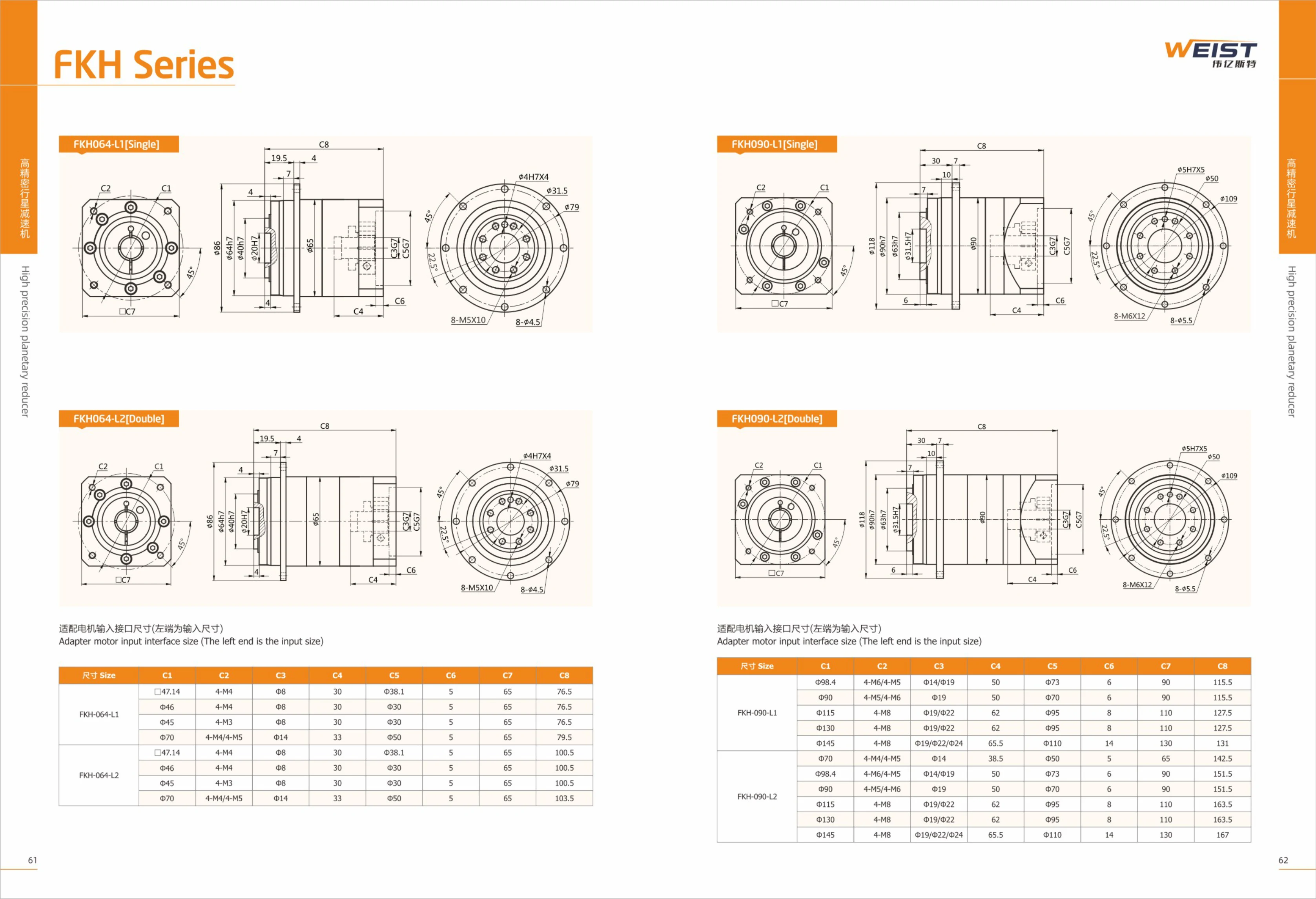
FKH Series
FKH series planetary gearboxes are designed for servo motors and are available in a range of flange sizes (064, 090, 110, 140) and lengths (L1, L2) to suit different motor interfaces. Precision manufacturing ensures smooth, quiet operation. They are widely used in automation equipment, machine tools, robotics, and other applications. The table lists the mounting dimensions (C1–C8) for each model to help customers select or replace a unit.
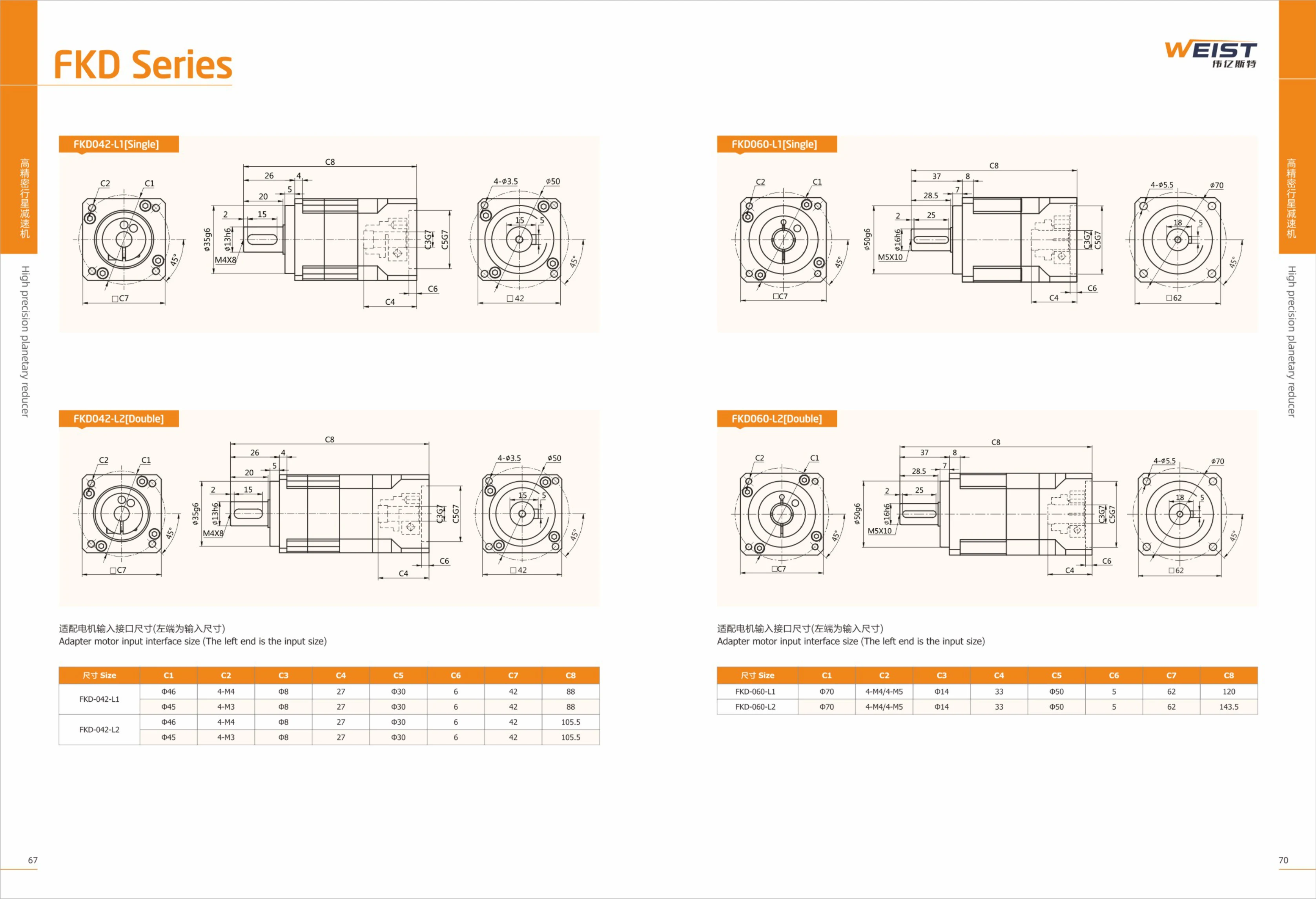
FKD Series Motor Connection Flanges
FKD Series motor connection flanges connect servo motors to loads or gearboxes and are available in a range of sizes and interface configurations. The series includes several models, such as FKD-042, FKD-060, FKD-090, FKD-115, and FKD-142, each available in two lengths: L1 and L2. The flanges offer multiple input dimensions (C1 to C8) to suit the mounting holes and shaft diameters of different motors. They are suitable for automation equipment, robots, CNC machine tools, and other applications, providing reliable connection and positioning.
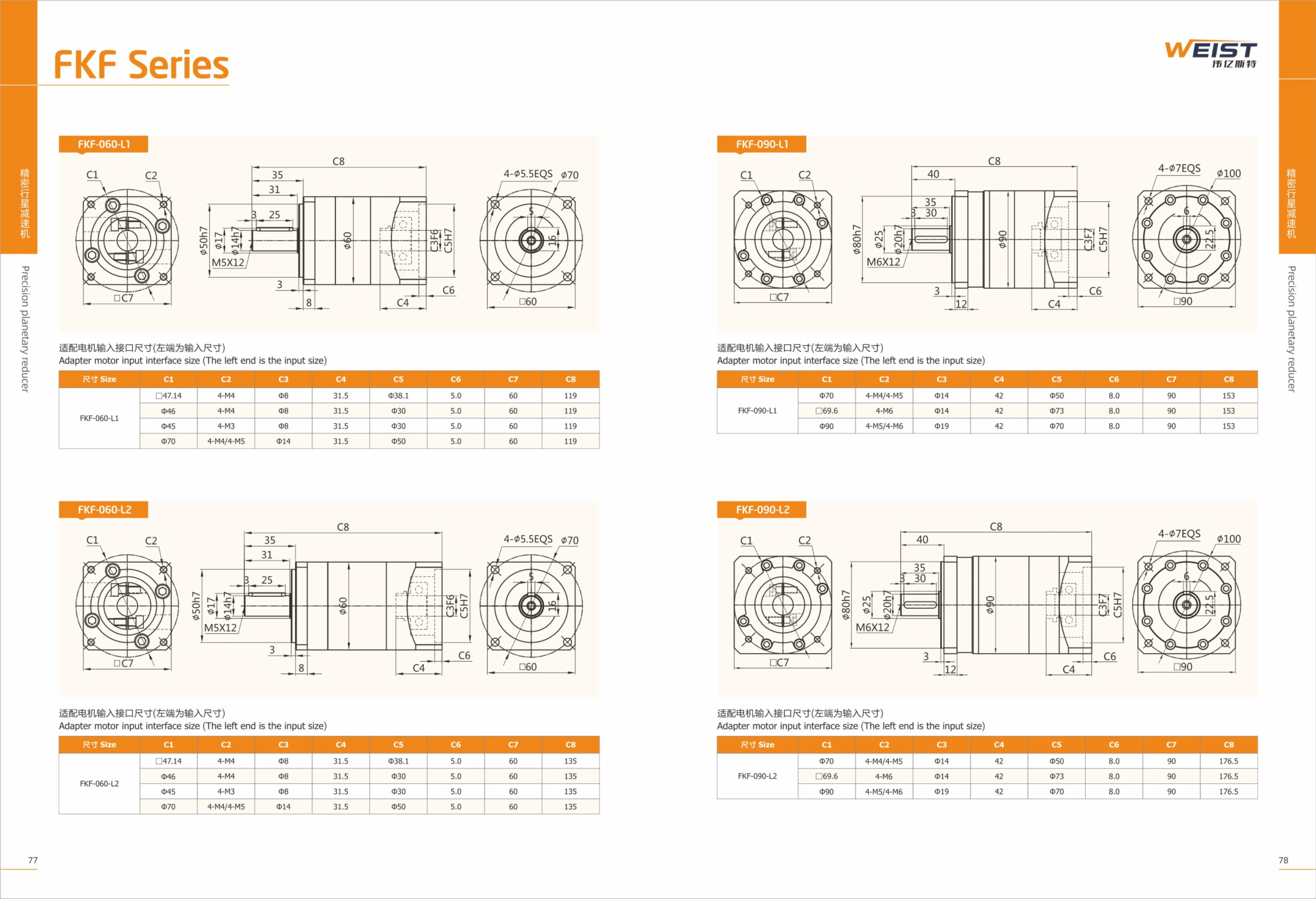
FKF Series Motor Interface Adapters
The FKF series adapts to motor input interface dimensions and is available in several models, including FKF-060-L1, FKF-060-L2, FKF-090-L1, FKF-120-L1, FKF-120-L2, and FKF-160-L1, to suit different motor mounting dimensions. The table lists interface parameters C1 through C8, including mounting hole spacing, hole diameter, and boss diameter, ensuring precise connection between the motor and the equipment. With a modular design, this series is widely used for motor drive connections in automation equipment.
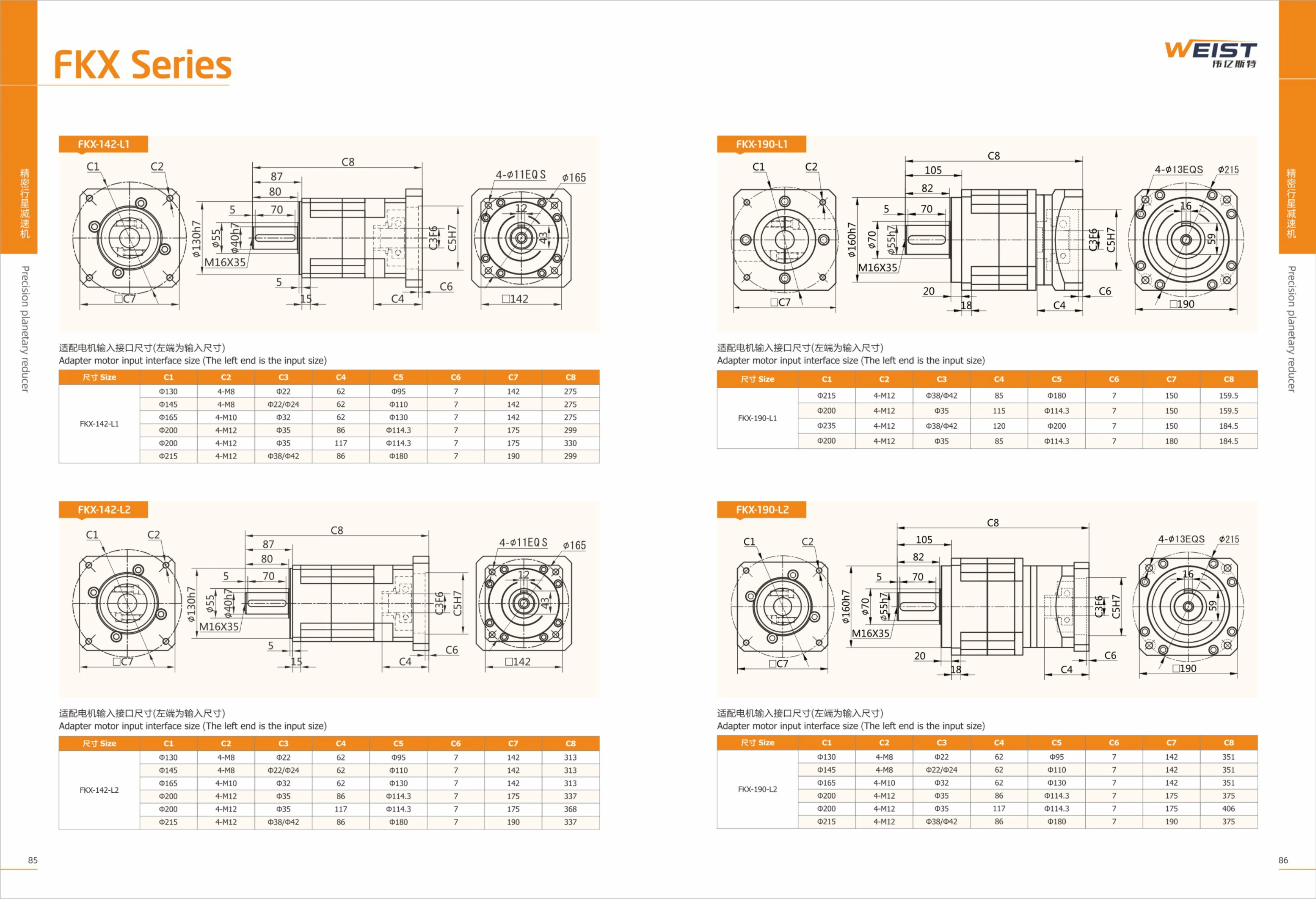
FKX Series Motor Interface Adapters
FKX series motor input interface adapters connect motors to loads and are available in various flange sizes and shaft bore specifications. The range includes two main models, FKX-142 and FKX-190, each available in two lengths, L1 and L2. They accommodate different motor interfaces (such as Φ130, Φ145, Φ165, Φ200, and Φ215), with mounting hole positions and depths varying by model. C1 indicates the adapter flange outer diameter; C2, the number and specifications of bolt holes; C3, the input shaft bore diameter; C4, the shaft extension length; C5, the mounting face outer diameter; C6, the keyway width (where applicable); C7, the adapter thickness; and C8, the overall length. Suitable for a range of standard motor interfaces, these adapters are common drive connection components in automation equipment.
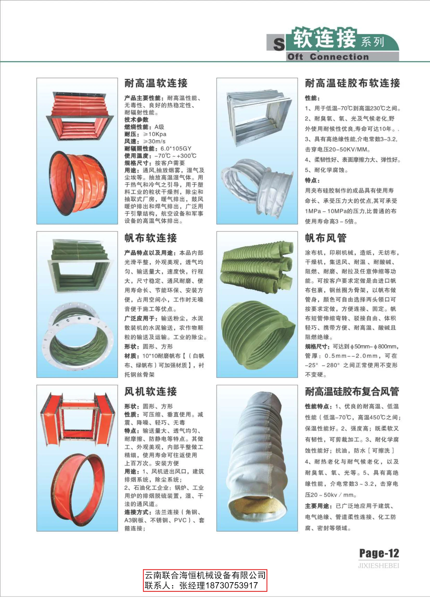
High-Temperature Silicone-Coated Fabric Flexible Connector
A high-temperature silicone-coated fabric flexible connector is used in high-temperature piping systems. Made from heat-resistant silicone-coated fabric, it offers excellent heat resistance (typically above 200°C), corrosion resistance, vibration and noise reduction, and compensation for thermal expansion and contraction. It is suitable for systems conveying high-temperature media, including ventilation ducts, flue-gas ducts, and chemical pipelines. Easy to install, it can effectively extend the service life of piping.
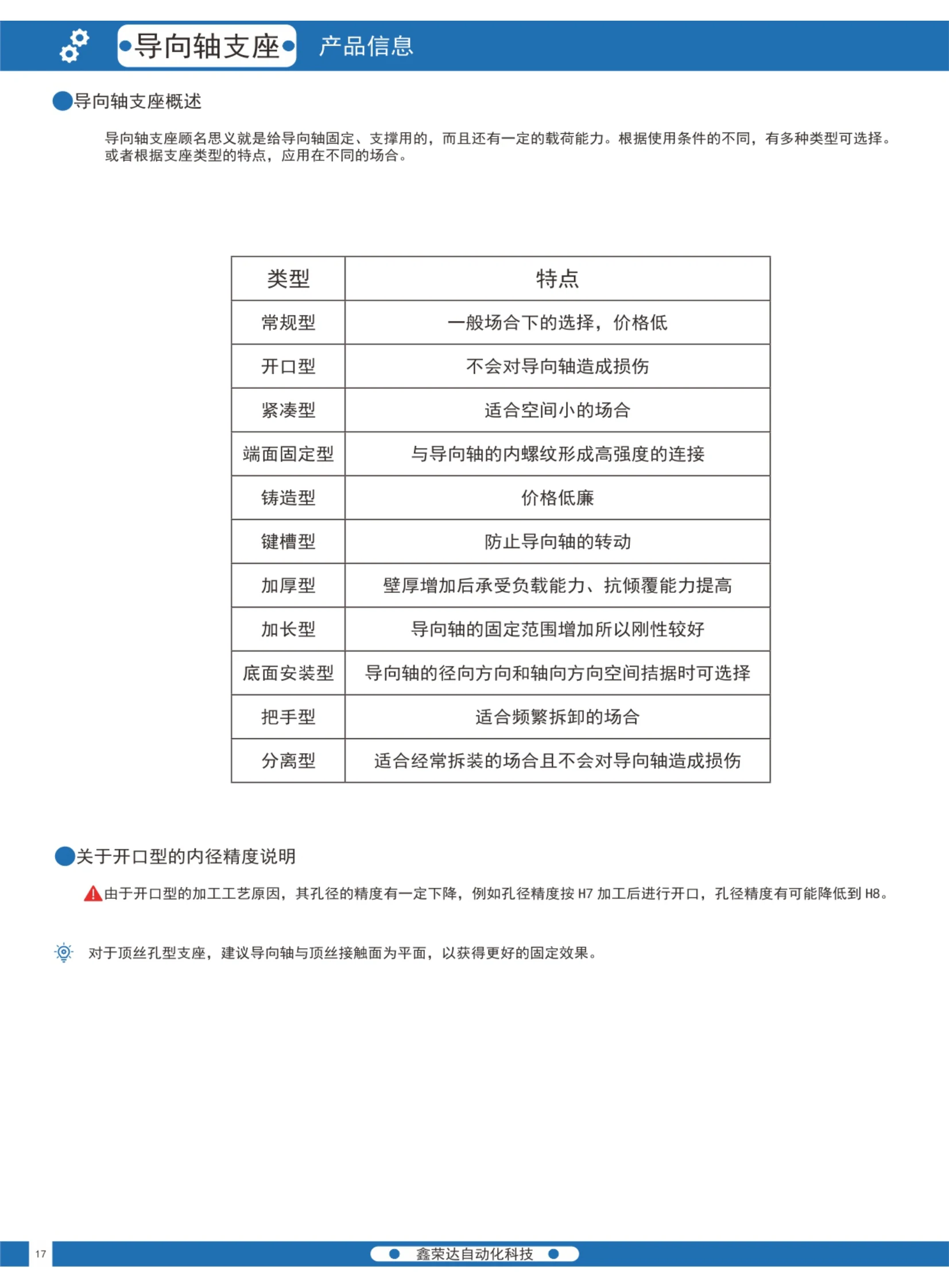
Guide Shaft Supports
Guide shaft supports secure and support guide shafts while bearing a certain load. They are commonly used in the linear-motion mechanisms of automation equipment and are often used with guide shafts and linear bearings. The catalog offers a variety of types to suit different operating conditions and mounting methods, including standard, slotted, compact, end-face mounting, cast, keyway, thick, extended, bottom-mounting, handle, and split types. The slotted type has reduced bore accuracy due to the slot machining, typically from H7 to H8. The catalog lists two code series—selectable-height and fixed-height types—with examples such as BLK01 and BLK12, and provides specifications and dimension tables for the mounting through-holes, whose bore tolerances are H7. Hex socket head cap screws are included as standard. Select a model according to the guide shaft diameter, mounting height, available space, and frequency of assembly and disassembly.
Carbon Steel Leveling Feet Series
The carbon steel leveling feet series provides adjustable supports for heavy equipment. The adjusting screw is grade 88, and the base is cast from 45# steel with an elastic polyurethane (TPU) pad bonded to the bottom. The TPU layer offers high resilience, shock absorption, slip resistance, and resistance to wear, oil, acids, alkalis, chemical corrosion and radiation. Its breaking strength is approximately 2~10 times that of natural rubber. These feet are used for leveling and vibration damping in heavy machinery and equipment. They feature high wear resistance, easy load support, high-temperature resistance, a thickened and reinforced construction, and flexible swiveling. The catalog lists various thread sizes and lengths for base diameters of 50/60/80/100/120mm, with mounting heights and load capacities provided in the table. Adjusting screw lengths, sizes and metric or imperial threads can be ordered to customer requirements. The threaded rod is available in a chrome-plated or stainless steel finish, and the base is made of carbon steel.
Nylon Leveling Feet Series
The nylon leveling feet series features grade 8.8 screws and premium imported nylon (PA6) bases. The chrome-plated screws resist impact, knocks and corrosion and allow directional adjustment. The bases contain SEBS elastomer, providing high resilience, shock absorption, slip resistance, and resistance to wear, oil, tearing, chemical corrosion and radiation. Load capacity ranges from 500~4000kg, base diameter from 50~100mm, thread size from M10~M30, screw length from 50~200mm, and total mounting height from 29~50mm. Suitable for leveling and vibration-damping support of machinery, workshop equipment and production lines. Screw length, size and tolerance system can be customized to customer requirements.
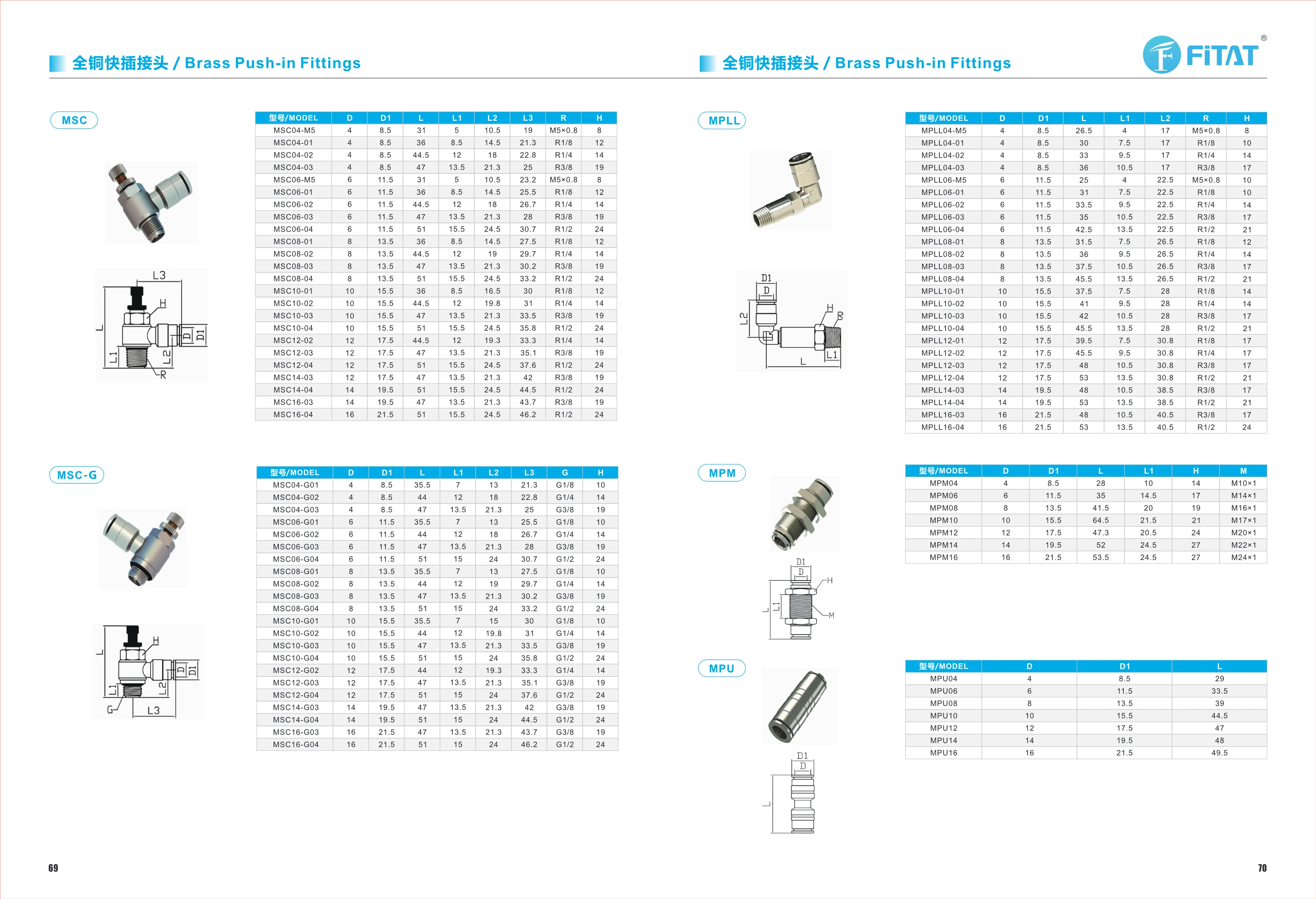
MPM Series Threaded Connection Accessories
The MPM series consists of connection accessories with fine-pitch external threads. Five sizes are available by bore (mating) diameter D: MPM08, MPM10, MPM12, MPM14 and MPM16, with M16×1, M17×1, M20×1, M22×1 and M24×1 fine-pitch external threads, respectively. The dimensions are defined by bore diameter D (8~16 mm), outer sleeve diameter D1 (always D+5.5 mm), overall length L (41.5~64.5 mm), threaded section length L1 (20~24.5 mm) and hex width across flats H (19~27 mm). Overall size increases with D. The bore accommodates a shaft or rod of the corresponding diameter, while the fine-pitch thread secures the accessory to the mating component. The hex section H provides a wrench grip. These accessories are suitable for threaded transitions and fastening where installation space is limited. Smaller MPL sizes (MPL04-M5 and MPL06) are also available for smaller rod diameters. To select a model, first determine D from the rod diameter, then select M and L1 to match the mating thread, and finally check that L fits the available space.
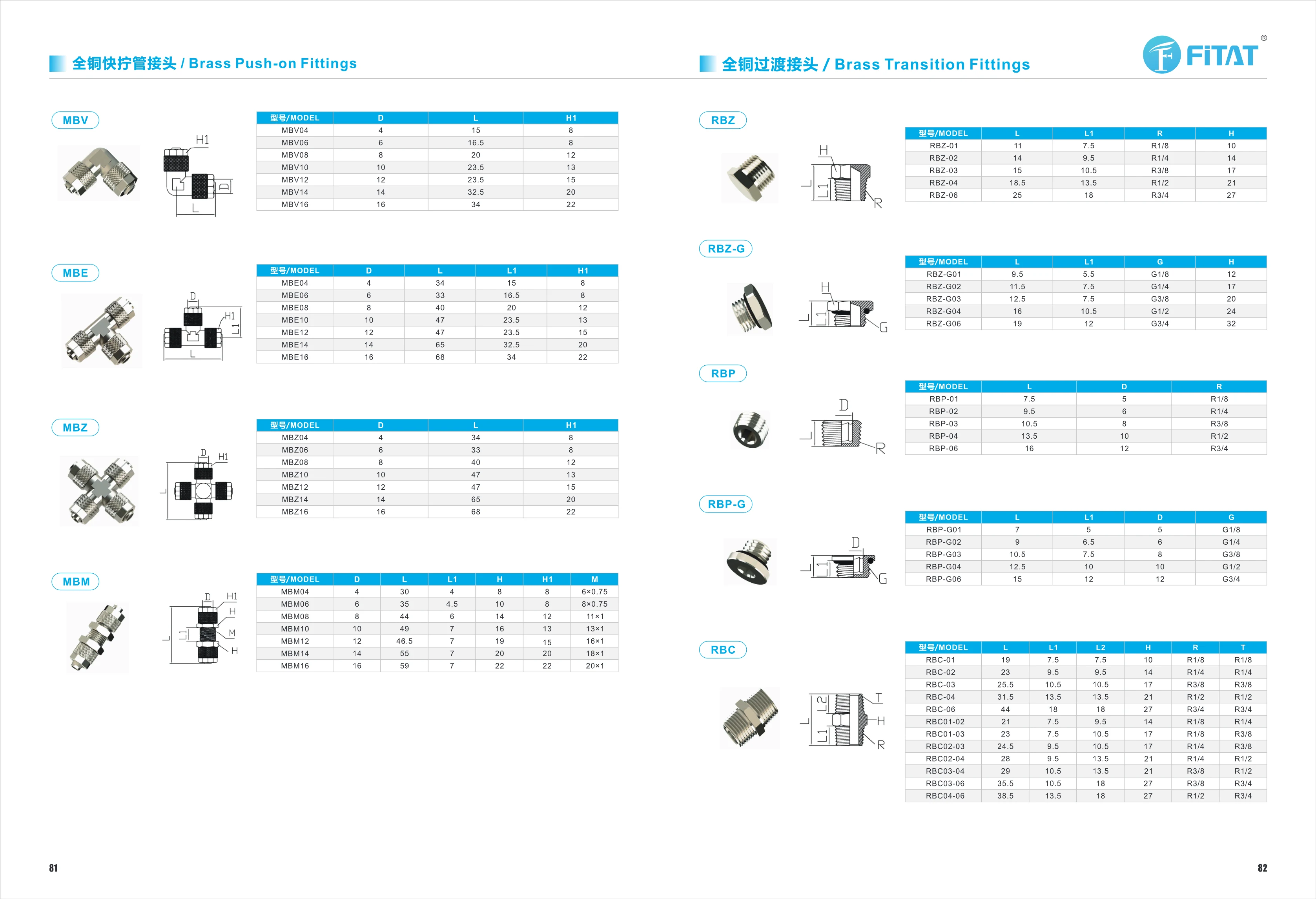
MBV Series Small Connection Accessories
The MBV series comprises small connection accessories for factory automation equipment. It is available in seven nominal sizes: MBV04, MBV06, MBV08, MBV10, MBV12, MBV14, and MBV16, with nominal diameters D of 4, 6, 8, 10, 12, 14, and 16 mm, respectively. Dimensions generally increase with the size designation: overall length L ranges from 15 mm for MBV04 to 34 mm for MBV16, while mounting height H1 ranges from 8 mm to 22 mm. Note that MBV10 and MBV12 both have an L of 23.5 mm, but their H1 values are 13 mm and 15 mm, respectively. To select a model, first determine the MBV size based on the nominal diameter or thread size of the mating component, then check that overall length L and height H1 meet the available mounting space and travel requirements. When multiple accessories are used on the same equipment, ensure consistent H1 values to maintain coaxial alignment during assembly. Common materials include zinc-plated carbon steel and stainless steel, suitable for connection and mounting needs in general industrial environments.
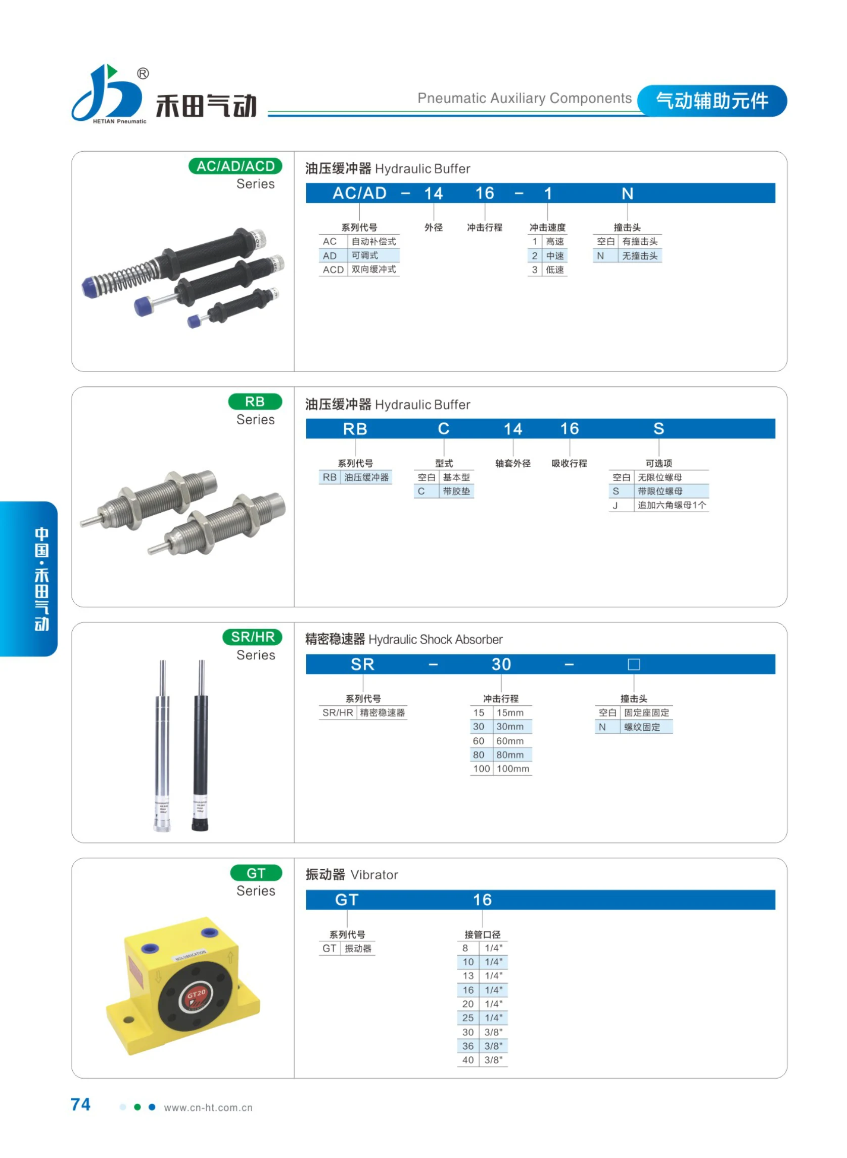
AC/AD/ACD Series Hydraulic Shock Absorbers
AC/AD/ACD series hydraulic shock absorbers are installed at the end of travel of moving mechanisms such as cylinders, slides, and conveyor lines. They use hydraulic oil throttling to convert the kinetic energy of moving parts into heat, providing smooth deceleration, reducing impact and noise, and protecting equipment and workpieces. The series is divided into AC, AD, ACD, and other subseries by design and application, with options for different mounting methods, shock absorber strokes, and energy absorption capacities. Selection generally requires calculating the required energy absorption based on the mass and impact velocity of the moving object, mounting orientation, and number of impacts per hour, then determining the appropriate size and quantity. This page is only a series title page and does not provide parameter tables for specific model codes, strokes, threaded connections, or energy absorption capacities. Refer to the dimension tables and model code descriptions on subsequent pages for detailed specifications.
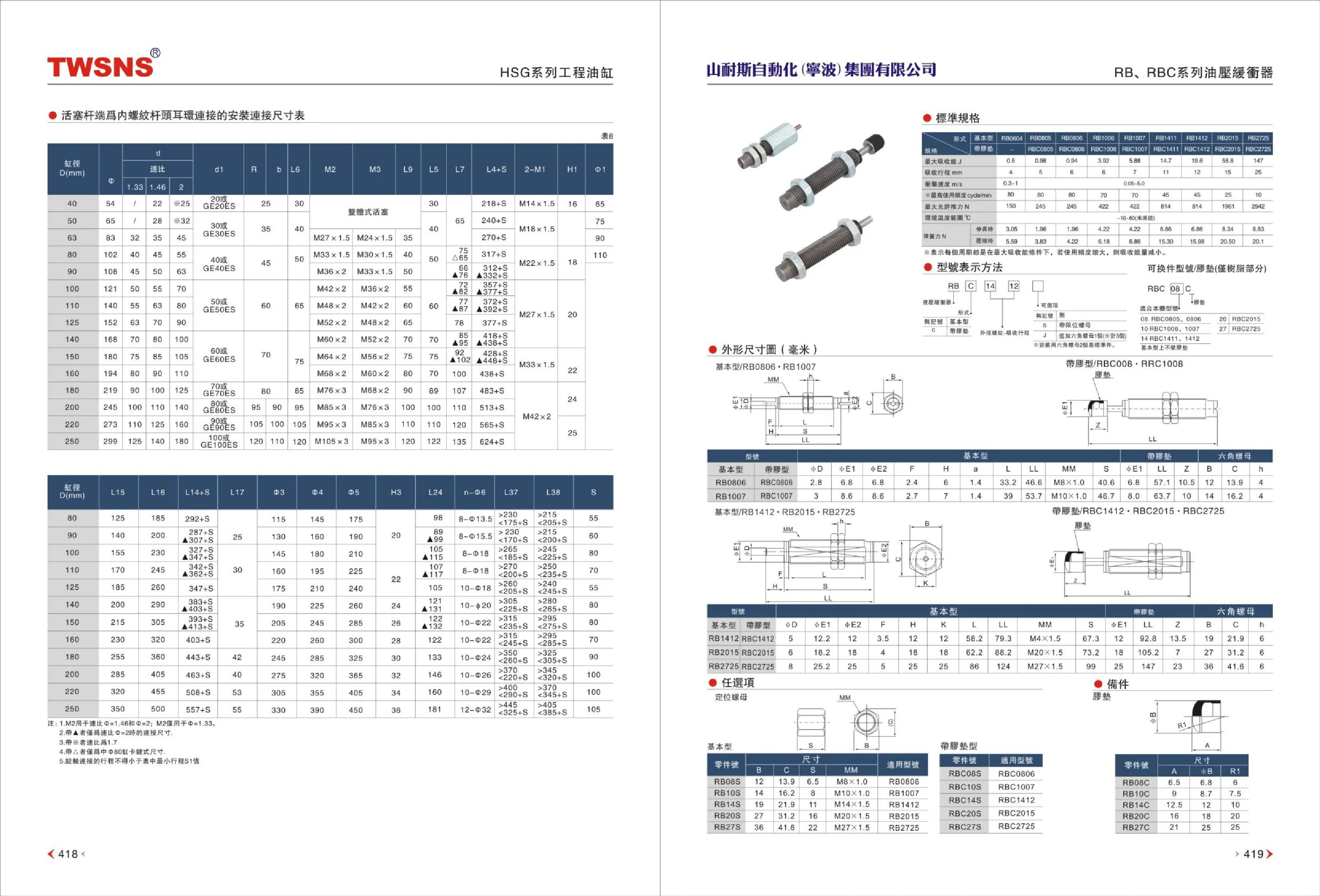
RB and RBC Series Hydraulic Shock Absorbers
RB and RBC series hydraulic shock absorbers absorb impact energy from moving parts in automated equipment, reducing noise and vibration while protecting equipment, fixtures, and workpieces. Standard catalog models include RB0604, RB0805, RB0806, RB1006, RB1007, RB1411, RB1412, RB2015, and RB2725, with maximum energy absorption of approximately 0.5~147 J and strokes of 4~25 mm. Smaller models are suitable for light loads and short strokes, while larger models are designed for heavy loads and high-impact conditions. Selection should take into account impact energy, stroke, impact velocity, mounting method, and environmental conditions.
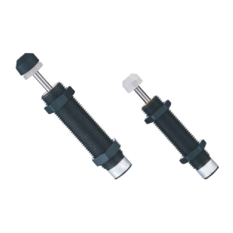
AC Series Self-Compensating Shock Absorbers
AC series self-compensating shock absorbers absorb impact energy and reduce vibration and noise in industrial automation equipment. They provide end-of-stroke cushioning for cylinders, slides, conveyor lines, and similar equipment. The self-compensating design accommodates a range of impact speeds. The externally threaded body ranges from M6×1 to M36×1.5, with strokes of 5~80 mm. The catalog lists models AC0806, AC1005, AC1008, AC1210, AC1412, AC1416, AC1420, AC2016, AC2020, AC2030, AC2050, AC2525, AC2550, AC2580, AC2540, and AC3660, with overall dimensions A~I provided for installation and selection.
AC/AD Series Shock Absorbers
AC/AD series shock absorbers (industrial hydraulic shock absorbers) absorb impact energy and reduce noise and vibration in automation equipment, at cylinder end positions, and on conveyor lines. AC denotes the self-compensating type (no adjustment required), while AD denotes the adjustable type (damping force can be adjusted to the load). Model numbers consist of the series code (AC/AD) + outside diameter (2 digits) + impact stroke (2 digits). For example, AC1416 indicates an outside diameter of 14mm and a stroke of 16mm. Nominal thread sizes range from M6×1 to M36×1.5, with impact strokes of 5~80mm. The catalog lists overall dimensions A~I for each model to assist with installation and selection.

AD Series Hydraulic Shock Absorbers
AD series adjustable hydraulic shock absorbers absorb impact energy from moving machinery for smooth deceleration and precise positioning. A multi-orifice throttling structure provides hydraulic damping, and the damping force can be adjusted continuously to suit the load and impact velocity. AC self-compensating models are also available and require no adjustment. Outer diameter sizes range from M14~M64, including the large UNF 2-1/2-12 size. Impact strokes range from 10~150mm, maximum impact velocities are approximately 1.5~4.5m/s, and the operating temperature range is -10~80℃. They can accommodate impact energy from applications ranging from small pneumatic cylinders to heavy-duty mechanisms handling large loads. Model numbers combine the series code (AD adjustable/AC self-compensating), outer diameter, impact stroke, impact velocity (1 high speed/2 medium speed/3 low speed), and cap option (blank with cap/N without cap). Standard model components are written consecutively, as in AD1410 (outer diameter 14, stroke 10). They are widely used for end-of-travel cushioning and collision protection in automated equipment, conveyor lines, machine tools, packaging machinery, and lifting equipment.
AD Series Adjustable Hydraulic Shock Absorbers
The AD series consists of adjustable hydraulic shock absorbers designed to absorb impact and reduce noise at the end of travel in automated equipment, conveyor lines, pneumatic cylinders, robotic arms, and similar applications. Damping force can be adjusted for different impact speeds, with high, medium, and low settings available. The shock absorber assembly is available with or without a damping cap (N). Key specifications include an outside diameter of 14~64 mm, threads from M14×1.5~M42×1.5 and UNF2 1/2-12, a stroke of 10~150 mm, maximum energy absorption of approximately 20~36000 J, a maximum impact speed of approximately 1.5~4.5 m/s, and an operating temperature of -10~80 ℃. The table lists standard models including AD1410, AD2016, AD2525, AD3625, AD4225, AD4250, AD4275, and AD-64050. Only dimensional data is provided for some models.

AC Series Hydraulic Shock Absorbers
AC series hydraulic shock absorbers are automation components that use hydraulic throttling to absorb impact kinetic energy and bring machinery to a smooth stop at the end of its travel. They are widely used for end-of-travel cushioning in cylinders, slides, conveyor lines, and robotic arms. Models are classified by bore and stroke combinations (such as AC2540, AC4250, and AC46050), with strokes of 25~150mm, maximum energy absorption per cycle of 115~4200Nm, and energy absorption per hour of 75000~260000Nm. Each model is available in three impact-speed versions: -1 high speed, -2 medium speed, and -3 low speed, with maximum impact speeds of 3/2/1m/s, respectively. The maximum effective weight is specified for each speed range (for example, AC2540: 300kg at high speed, 900kg at medium speed, and 1400kg at low speed). Both energy and effective weight must be checked when selecting a model. Mounting thread sizes range from 1/2"-1", allowing direct compatibility with various mechanical interfaces.

AD Series Shock Absorbers
AD Series shock absorbers are industrial hydraulic shock absorbers designed to absorb impact energy from moving mechanisms and reduce vibration and noise. The catalog provides a complete model list organized by stroke and cylinder bore, with specifications covering strokes of 16~50 mm, maximum energy absorption per cycle of 35~250 Nm, energy absorption per hour of 39000~95000 Nm/h, and maximum effective weights of 220~720 kg. The series includes standard and low-speed versions (model suffix -5). Some models have a -C suffix (such as AD2016-C and AD2540-C) and have slightly different energy absorption ratings from standard models with the same stroke. S Series non-adjustable models (see the corresponding page for specifications and dimensions) and A Series adjustable models are also available. Select the stroke and energy absorption capacity based on the moving component's impact speed, total weight, and number of cycles per hour, ensuring that neither the per-cycle nor hourly energy absorption rating is exceeded. These shock absorbers are widely used for end-of-stroke cushioning and controlled deceleration during positioning on pneumatic slides, conveyor lines, and automated assembly equipment.
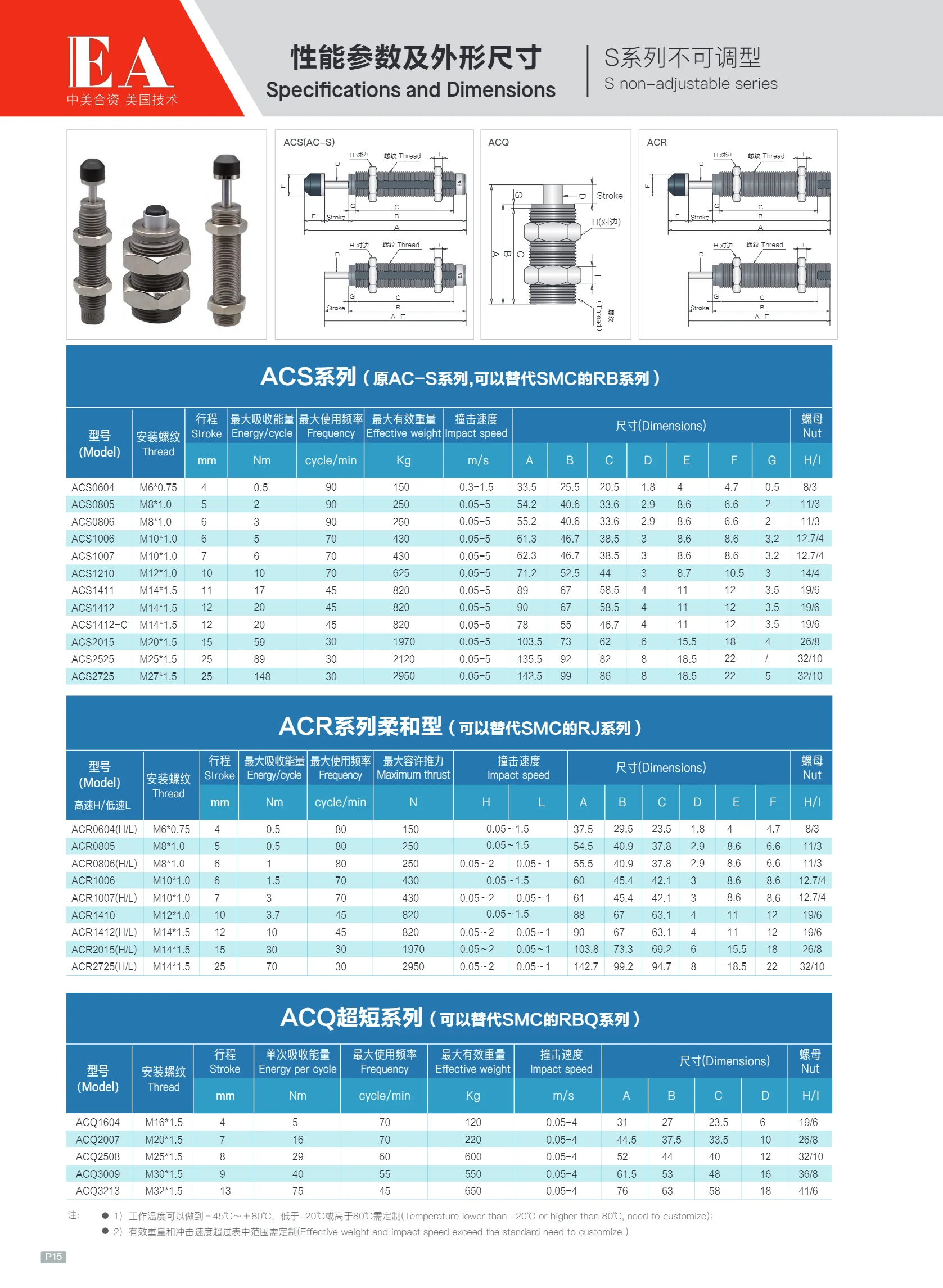
ACS Series Non-Adjustable Shock Absorbers
The ACS series non-adjustable shock absorbers, formerly the AC-S series, absorb impact energy and reduce noise and vibration. They can replace the SMC RB series. Models include ACQ6040H(L), ACQ8050, and ACQ1200H(L), with mounting threads of M6×0.75, M8×1.0, and M14×1.5. Stroke lengths range from 4~320 mm (10~320 mm in 5 mm increments for ACQ1200H(L)). Maximum energy absorption ranges from 0.5~2.0 J, maximum operating frequency is 80 cycles/min, and maximum effective weight ranges from 0.05~1.5 kg. The non-adjustable design requires no adjustment and is suitable for automated equipment, conveyor lines, cylinder end stops, and other applications requiring impact absorption.

S Series Non-Adjustable Shock Absorbers
The S series of non-adjustable shock absorbers includes the ACS subseries (formerly AC-S) and can replace the SMC RB series. The fixed-orifice design provides consistent impact energy absorption for end-of-travel cushioning in automated mechanisms such as cylinders and slide tables. Catalog models include ACQ6040H(L), ACQ8050, and ACQ1200H(L), with mounting threads of M6×0.75, M8×1.0, and M14×1.5. Stroke lengths include 4 mm, 5 mm, and 10~320 mm for ACQ1200H(L) (in 5 mm increments). Maximum energy absorption is 0.5~2.0 J, maximum operating frequency is 80 cycles/min, and maximum effective weight is 0.05~1.5 kg. Select a model based on impact speed, load mass, and available mounting space.
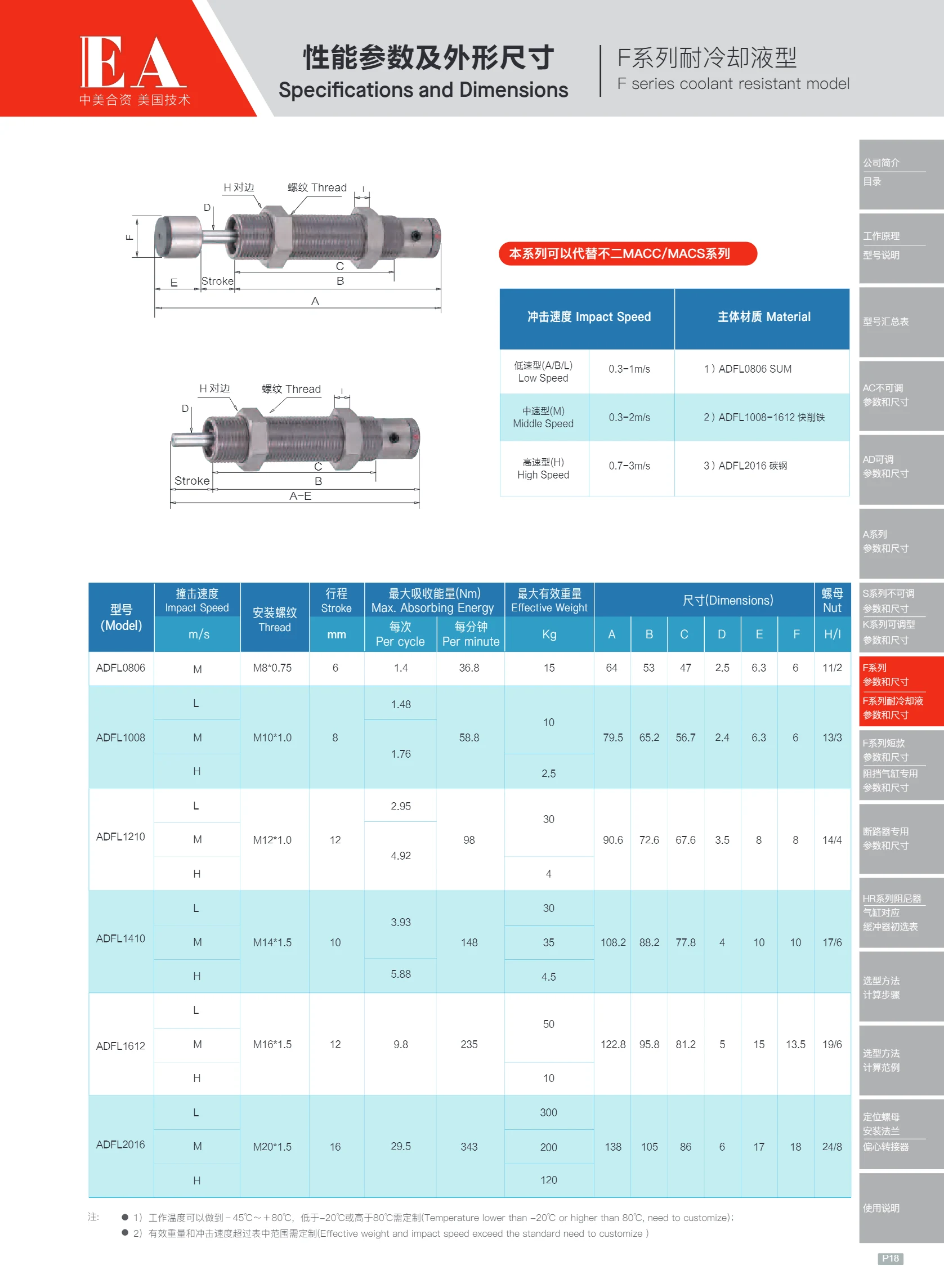
S Series Non-Adjustable Shock Absorbers
S Series (ADFL Series) non-adjustable shock absorbers are self-compensating hydraulic shock absorbers that require no adjustment. They absorb shock and reduce noise at the end of travel of high-speed moving components such as cylinders, slides, and conveyor lines, providing consistent shock absorption without manual adjustment. The model number consists of ADFL + a two-digit mounting thread code + a two-digit stroke code. For example, ADFL1210 denotes an M12×1.0 thread and a 10mm stroke. Available specifications cover six mounting threads: M8×0.75, M10×1.0, M12×1.0, M14×1.5, M16×1.5, and M20×1.5, with strokes of 6~16mm. Each size is available in three impact-speed ratings: M (medium speed), H (high speed), and L (low speed), with corresponding maximum energy absorption (Nm) and maximum effective weight (kg) values. When selecting a model, check all three criteria: energy absorption, effective weight, and impact speed. The compact, maintenance-free body is threaded for mounting and supplied with a lock nut.
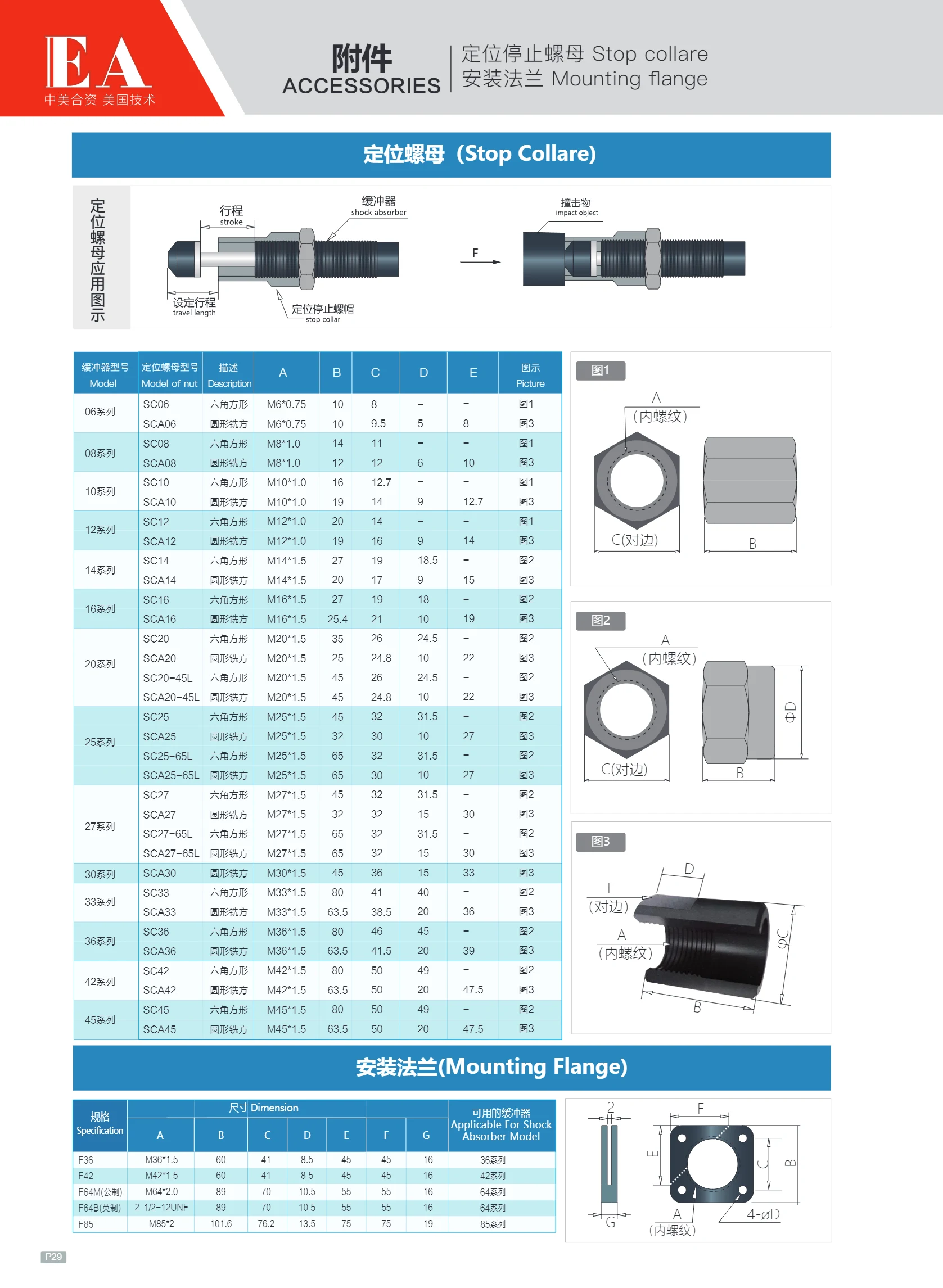
Shaft Collars
Shaft collars, also known as stop collars or limit rings, position and restrain components axially on a shaft. The collar fits over the shaft and is secured with a side set screw or a split-clamp mechanism, preventing bearings, sprockets, pulleys, gears and other components from moving along the shaft. The mounting flange style shown here adds a flange face and mounting holes to the collar, allowing it to be bolted directly to a frame, panel or slide table for easy attachment of stops, sensor brackets, limit switch actuators and other accessories. Common materials include carbon steel with a black oxide or zinc-plated finish, stainless steel and aluminum alloy. Sizes are based on the compatible shaft diameter; when selecting a collar, check the shaft diameter, flange dimensions and mounting hole spacing.
Mounting Flanges
Mounting flanges are accessories for locating nuts (stop rings and shaft collars). They use screws to secure the locating nut axially to a panel, frame, or equipment end face, providing axial positioning, preventing rotation, and ensuring flush mounting. Common materials include carbon steel with a black oxide or zinc-plated finish and stainless steel. Designs include single-slot, double-slot, and raised-boss types, with mounting holes typically countersunk or threaded. When selecting a flange, match it to the bore diameter, outside diameter, and width of the corresponding locating nut, and check the mounting hole center spacing, flange outside diameter, and thickness. This catalog page provides only the title of the mounting flange dimension table; it does not list specific dimensions or model codes. Refer to the selected locating nut's specification page and corresponding drawing for actual dimensions.
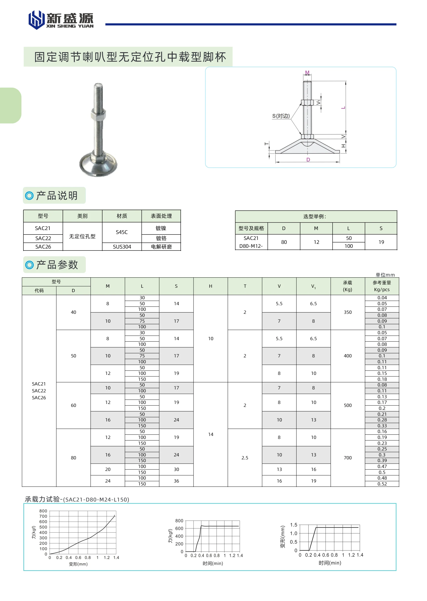
SAC/SAD Series Adjustable Leveling Feet
This series includes a variety of adjustable leveling feet for applications ranging from light-duty to ultra-heavy-duty. The main types are fixed-adjustment, horn-shaped, medium-duty feet without locating holes (SAC21/22/26); horn-shaped, medium-duty feet with locating holes (SAC31-34); all-PA base feet (SAD26-28); light-duty vibration-isolating feet with all-rubber bases (SAC02/05/06); economical heavy-duty vibration-isolating feet with carbon steel and rubber bases (SAC51/52/55/56); fixed-adjustment, vibration-isolating or non-isolating, ultra-heavy-duty precision feet (SAC61-63); fixed-adjustment, ultra-heavy-duty precision non-slip feet (SAC71/72); and round bases for precision leveling feet (SAC96/97). Materials include carbon steel, SUS304, PA, and NBR rubber. Surface treatments include nickel plating, chrome plating, zinc plating, and electrolytic polishing. Thread sizes range from M12 to M60, as well as trapezoidal threads such as Tr42x6. Load capacities range from 100kg to 11000kg. Suitable for supporting, vibration isolation, and leveling a wide range of industrial equipment.

SAD Series Leveling Feet
This series includes a variety of leveling feet: fixed-adjustment, rubber-padded, fine-adjustment, all-nylon base, heavy-duty with bearing, heavy-duty with handle, anti-vibration and anti-slip, and economical anti-slip types. They are suitable for supporting, leveling, and vibration damping in industrial equipment. Materials include SUS304 stainless steel, S45C carbon steel, and PA6-GF25 nylon. Surface finishes include nickel plating, chrome plating, electrolytic polishing, and black electrophoretic coating. Thread diameters range from M8 to M24, base diameters from 20 to 160 mm, and lengths from 50 to 300 mm. Load capacities reach 1,000–3,400 kg.

Fine-Adjustment All-Stainless-Steel Heavy-Duty Leveling Foot
The SAD18 Series fine-adjustment, all-stainless-steel heavy-duty leveling foot is made of SUS304 stainless steel. Its base features a rubber pad, and its surface is treated with nitrile rubber, providing excellent corrosion resistance and shock absorption. Designed to support heavy equipment requiring precise leveling, it offers high load capacity and excellent stability. Thread diameters include 100 mm, 150 mm, and 200 mm, with screw lengths including 16 mm and 50 mm. The overall height and base diameter can be selected to suit specific requirements. It is widely used for supporting and leveling industrial machinery, automation equipment, conveyor systems, and other applications.

SAR Universal-Adjustable Light-Duty Leveling Feet
The SAR series of universal-adjustable light-duty leveling feet includes nylon-base models (SAR31/SAR32), models with rubber pads (SAR41/SAR42), and models without rubber pads (SAR61–SAR66). Nylon-base models are made of S45C or PA6 and have a black finish. For models with rubber pads, the screw is made of S45C with zinc or chrome plating, the base is PA6, and the pad is NBR. Models without rubber pads are made of S45C with a black finish. Designed for light-duty applications, they offer universal adjustment. Options include base diameter D (e.g., 50 mm), thread size M (e.g., M8, M10, M12, M16), and length L (e.g., 50 mm, 75 mm, 100 mm). Load capacity: 120–300 kg.

SAG Series Leveling Feet
SAG Series Leveling Feet are support and adjustment components commonly used in factory automation. They are available in swivel-adjustable and fixed-adjustable types, and in materials including all-nylon, reinforced polyacetal, and metals such as S45C and SUS304. Surface finishes include chrome and zinc plating. Load capacities range from 300 kg to 2,830 kg to suit different requirements. Some models feature rubber pads for vibration damping. Typical applications include supporting equipment bases and leveling worktables.
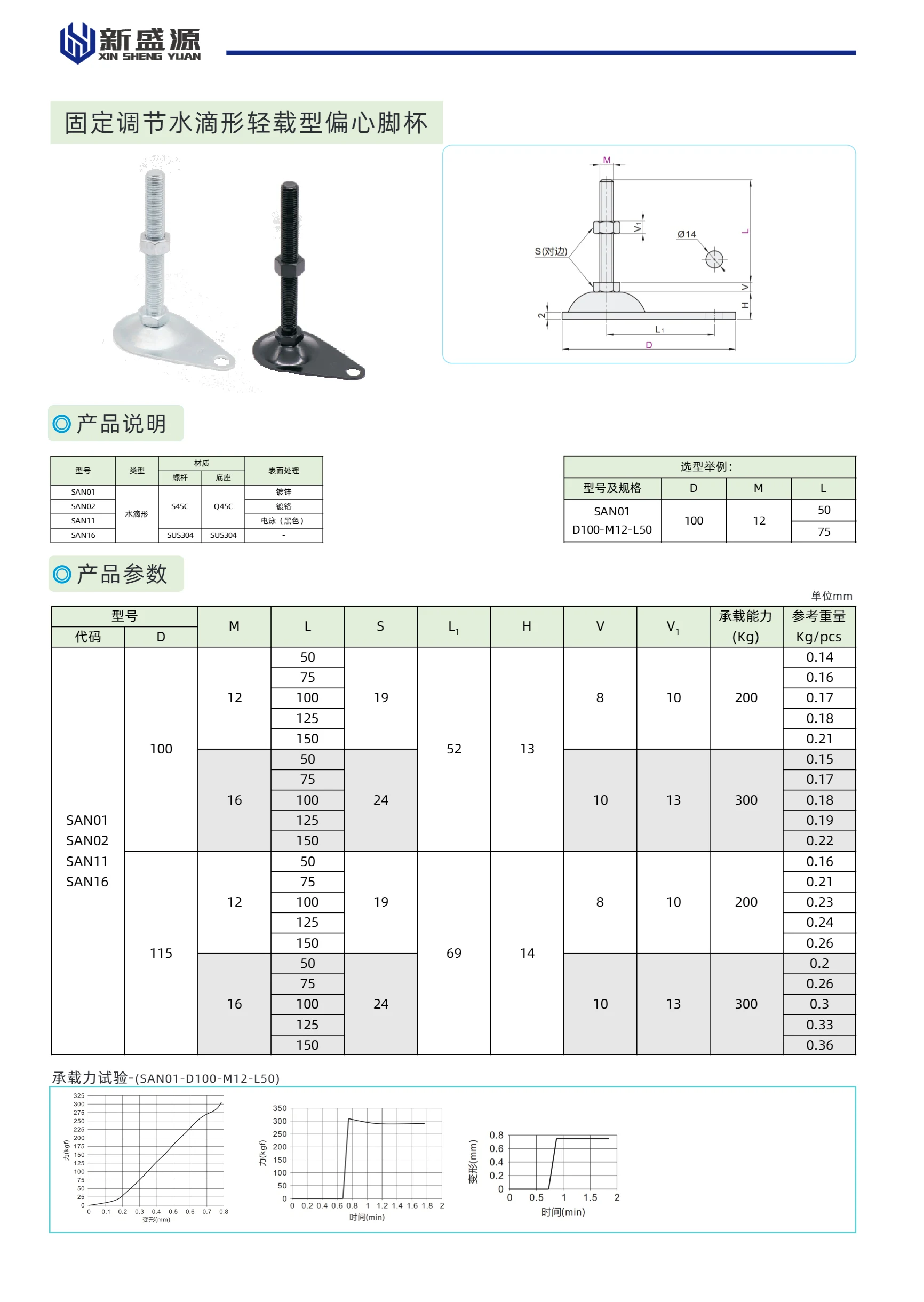
Fixed-Adjustment Light-Duty Eccentric Leveling Feet
This series of fixed-adjustment, light-duty eccentric leveling feet is designed for fine leveling and support in applications such as automation equipment, conveyor lines, and workbenches. Available in two shapes—teardrop (SAN01/02/11/16) and half-moon (SAN51/52/61/66)—the products are made from materials including threaded rod, S45C, and S35S04, with finishes such as zinc plating and black plating. They feature an M12 thread, lengths of 50–150 mm, a 19 mm hex size, a 10 mm offset, and load capacities of 50–200 kg. Their compact design and convenient adjustment make it easy to level equipment in confined spaces.
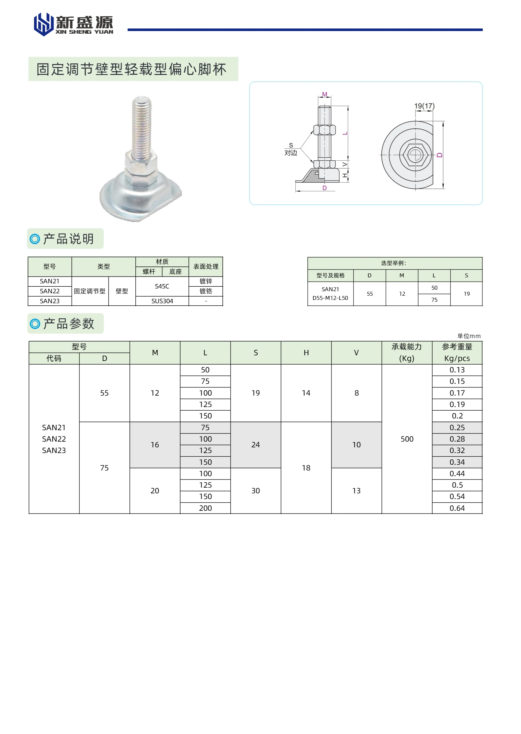
SAN Series Eccentric Leveling Feet
This series features fixed-adjustment, wall-mounted eccentric leveling feet for light loads. Models include SAN21, SAN22, and SAN23. SAN21 has a zinc-plated screw, SAN22 has a 45C chrome-plated screw, and SAN23 has a SUS304 stainless steel screw. The load capacity is approximately 8 kg, making these feet suitable for light-duty leveling applications. Dimension M is 55 mm; L ranges from 75 to 150 mm; S is 19 mm; H is 14 mm; and V is 18 mm. Reference weight varies with length, from 0.13 kg to 2.79 kg. Surface finishes are zinc plating, chrome plating, and untreated (stainless steel), respectively.
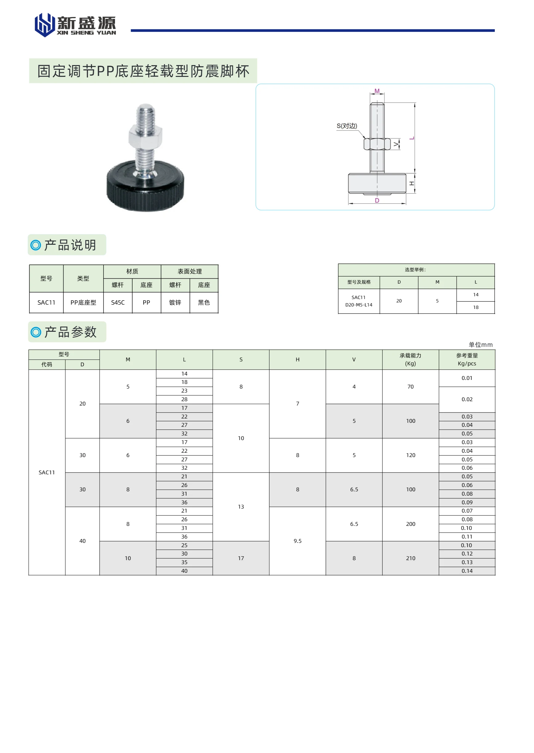
Fixed, adjustable light-duty anti-vibration leveling foot with PP base
This series features light-duty anti-vibration leveling feet with PP bases, model SAC11, made of PP with a black finish. The feet have adjustable height and are suitable for vibration damping and leveling of light-duty equipment. Various thread sizes and base diameters are available. Load capacity ranges from 70–120 kg, and the reference weight is 0.01–0.14 kg/pc. Key specifications include thread size M, length L, and base diameter D. Select according to your requirements.
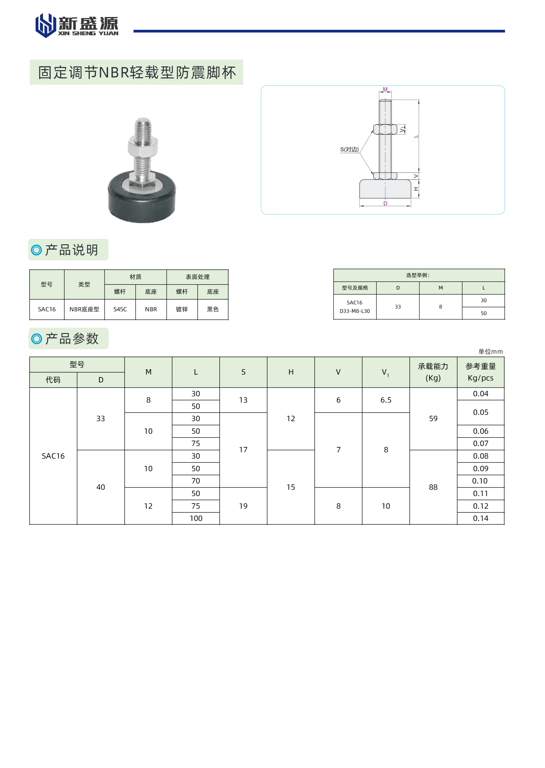
Fixed-Adjustment NBR Light-Duty Anti-Vibration Leveling Foot
This series of fixed-adjustment NBR light-duty anti-vibration leveling feet is model SAC16. The base is made of NBR (nitrile rubber), offering good vibration absorption and wear resistance. It has a zinc-plated finish and is black. Designed to support and reduce vibration in light-duty equipment, the height can be adjusted using the adjustment screw. Typical applications include automation equipment, conveyors, and workbenches.
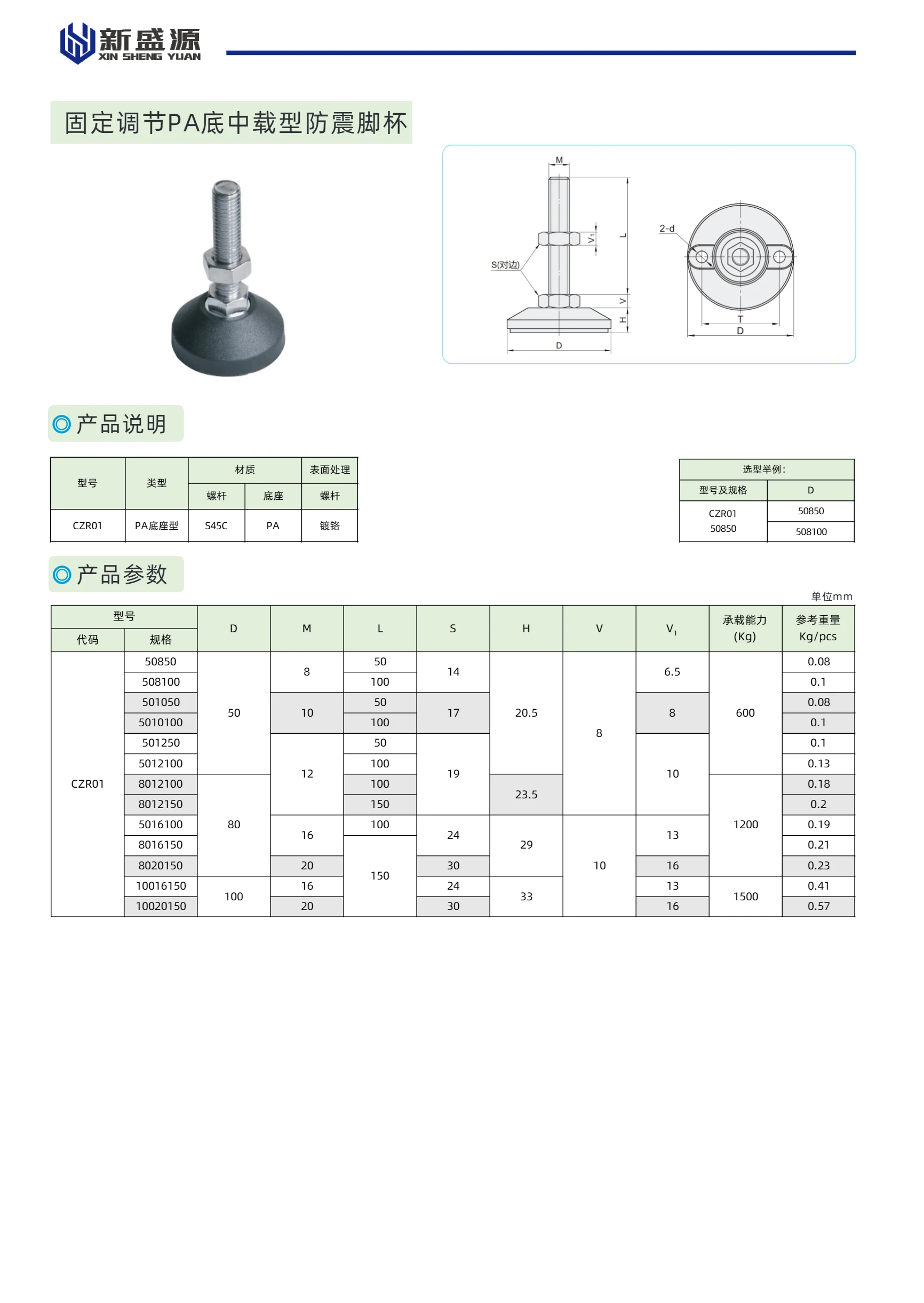
Fixed-Adjustment Medium-Duty Anti-Vibration Leveling Foot with PA Base
This series of fixed-adjustment, medium-duty anti-vibration leveling feet features a PA base and S45C steel construction with a chrome-plated finish. Designed to support and dampen vibration in medium-duty equipment, these feet are stable and easy to adjust, making them suitable for a wide range of applications, including automation equipment, conveyor lines, and workbenches.
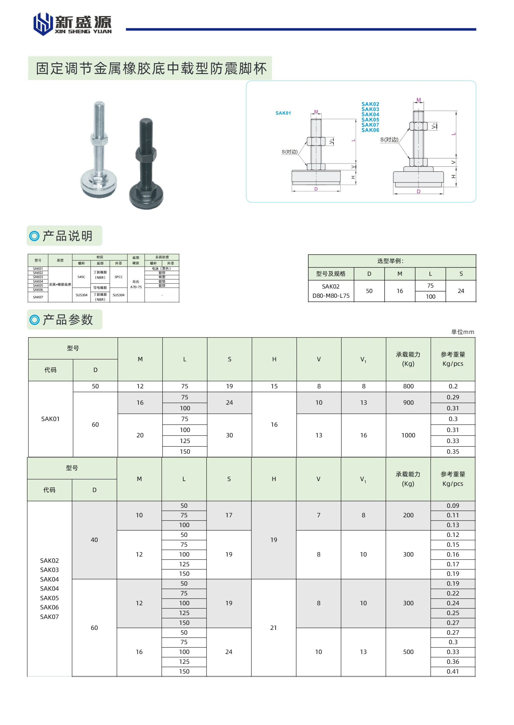
Fixed-Adjustment, Metal-Cover, Rubber-Base Medium-Load Anti-Vibration Leveling Mount
This series of fixed-adjustment, metal-cover and rubber-base anti-vibration mounts is designed to support industrial equipment and reduce vibration. Each mount features a metal cover (S45C) and a rubber base (NBR) with an anti-vibration rubber finish. Multiple models are available, with thread diameters (M) from 40 mm to 60 mm, lengths (L) of 10 mm or 12 mm, a base height (S) of 75 mm, overall heights (H) of 17 mm or 19 mm, and load capacities from 200 kg to 1,000 kg. Other models include SAK21, SAK22, and SAK26; detailed specifications are not provided. Suitable for vibration-isolating installation beneath a wide range of machinery.