Linear Motion Accessories — Page 16

LGC Series Crossed Roller Guides and Tables
The LGC series of three-row crossed roller guides is a standardized AIRTAC product line. Its rollers are arranged in three crossed rows to provide linear guidance with high rigidity, precision, and load capacity. The series comprises two subseries, LGC1A and LGC2A, with guide widths of 17 mm and 24 mm and heights of 4.5 mm and 6.5 mm, respectively. Lengths range from 20 mm to 180 mm, with increments varying by subseries. Counterbored mounting holes feature a consistent pitch—10 mm for the LGC1A series and 15 mm for the LGC2A series—for easy installation. These guides are suited to applications requiring compact linear guides, such as precision automated machinery, material-handling equipment, and industrial robots. Dynamic and static load ratings are calculated based on the number of rolling elements; exact values vary by model. The products meet AIRTAC standards and are compatible with leading brands on the market.
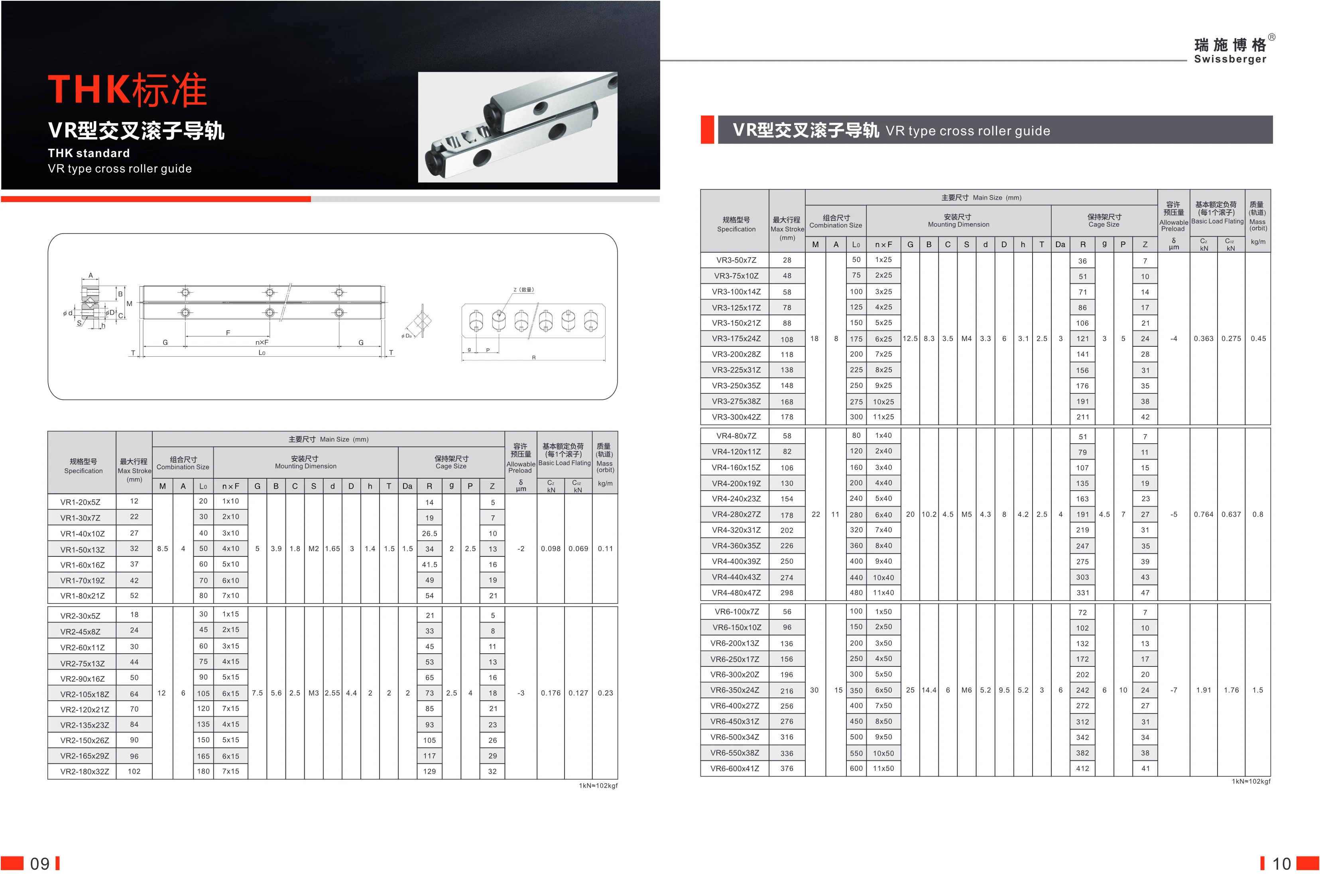
VR-type crossed roller guide
The THK-standard VR-type crossed roller guide is a high-rigidity linear motion component featuring a crossed roller arrangement for high load capacity and precision. The product range includes several sub-series, such as VR1, VR2, VR9, VR12, VR15, and VR18. Rail lengths range from 20 mm to 1,200 mm, with maximum strokes from 12 mm to 750 mm. It is suitable for automated equipment requiring high-precision guidance and heavy-load capacity, including machine tools, semiconductor equipment, and industrial robots. The guide consists of a cage and rollers, with a basic dynamic load rating of up to 4.31 kN per roller. Preload is adjustable, the unit is lightweight, and mounting dimensions are standardized.
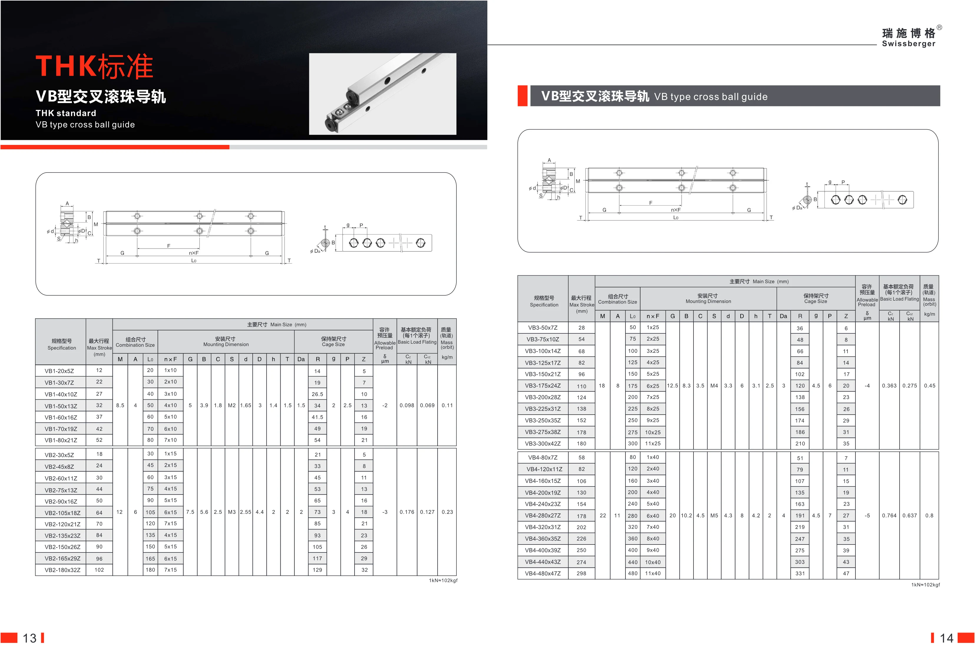
VB-type crossed roller guide
THK standard VB-type crossed roller guides feature a crossed-roller design for high rigidity and precision, making them ideal for precision positioning and linear motion in automation equipment. The series includes models such as VB1, VB3, VB4, and VB6, with strokes ranging from 12 mm to 298 mm. Different roller counts (Z suffix) are available to meet load requirements. The compact mounting dimensions, adjustable preload, and high rated load make these guides a versatile choice.
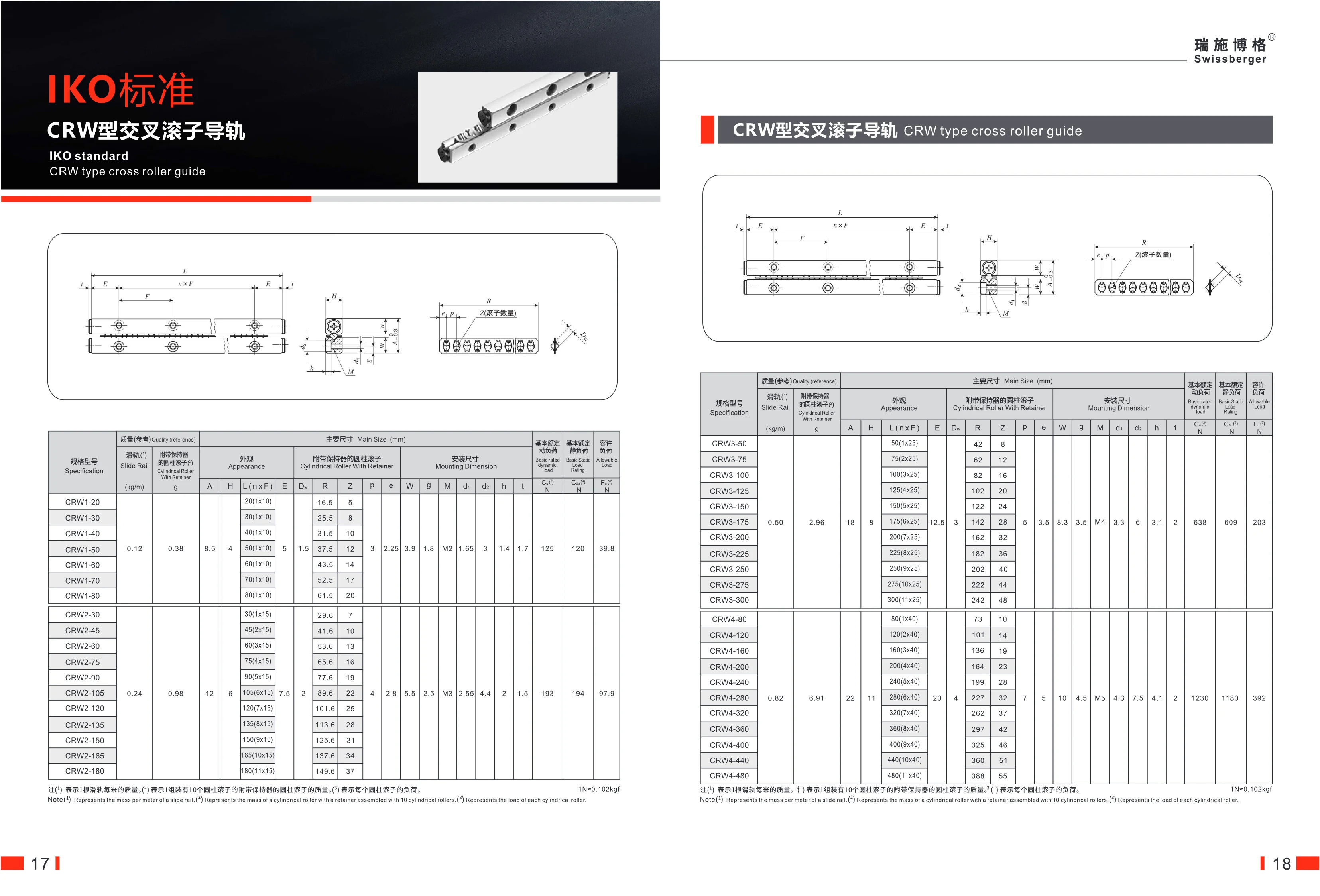
CRW-type crossed roller guide
CRW-type crossed roller guides are high-precision linear motion components that meet IKO standards. Their cylindrical rollers are arranged crosswise, allowing them to withstand loads in all directions. The series includes various sizes, such as CRW1, CRW3, CRW6, CRW9, and CRW12, each with a different guide width and rated load capacity. Lengths can be selected as required. These products are suitable for high-rigidity, high-precision automation equipment, including precision machine tools, semiconductor equipment, and medical instruments. Technical specifications such as key dimensions, rated dynamic load, static load, and allowable load are detailed in the catalog.
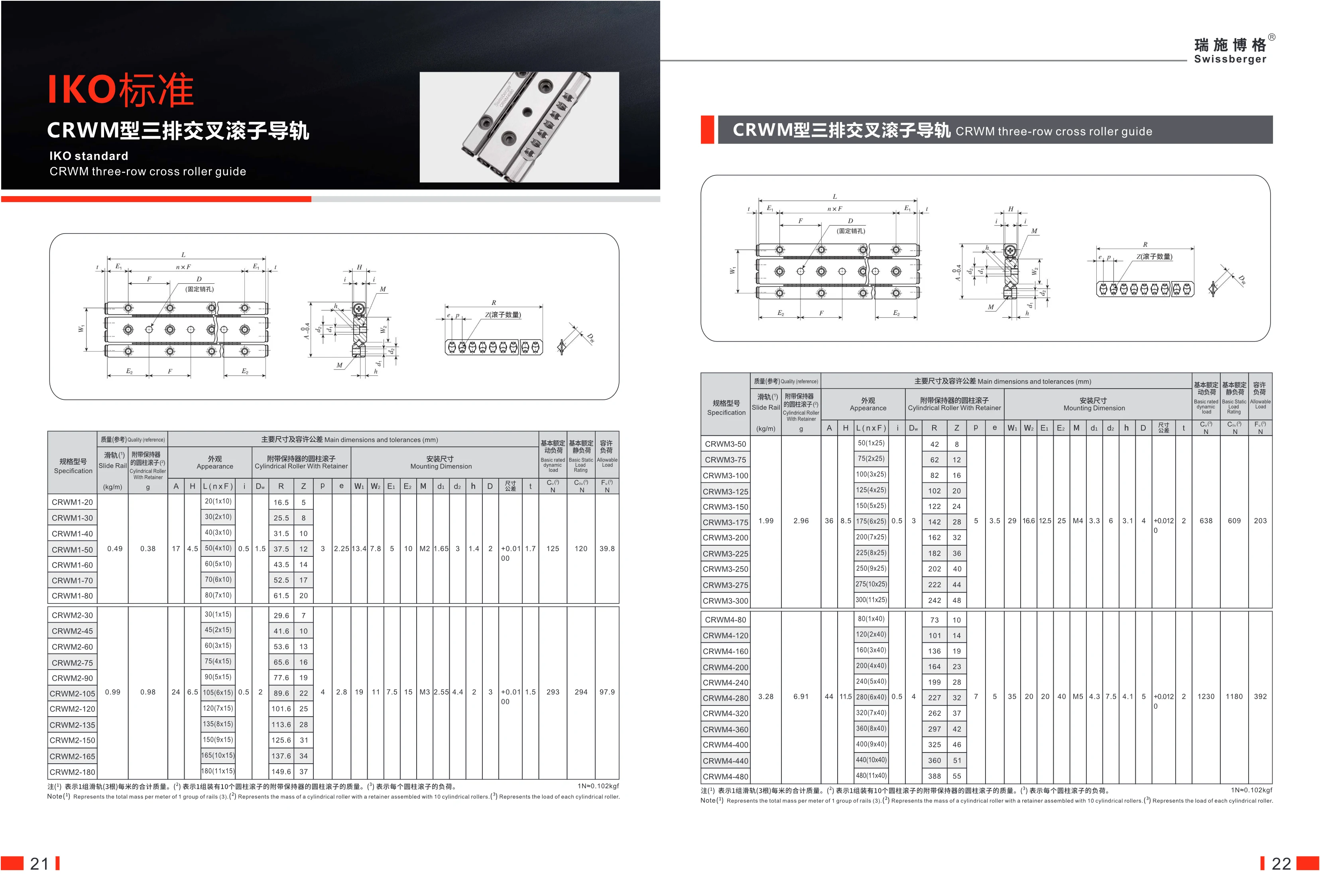
CRWM Three-Row Crossed Roller Guide
The CRWM three-row crossed roller guide is a standard IKO product. Its three-row cylindrical roller arrangement provides high rigidity, precision, and load capacity. It is suitable for linear motion applications requiring high load capacity and rigidity, such as machine tools, industrial robots, and precision measuring equipment. The guide is available in three width series—CRWM1, CRWM2, and CRWM3—with lengths ranging from 20 mm to 300 mm. Its basic dynamic load rating is at least 125 N, and it supports high permissible loads. Precise mounting dimensions ensure excellent interchangeability.
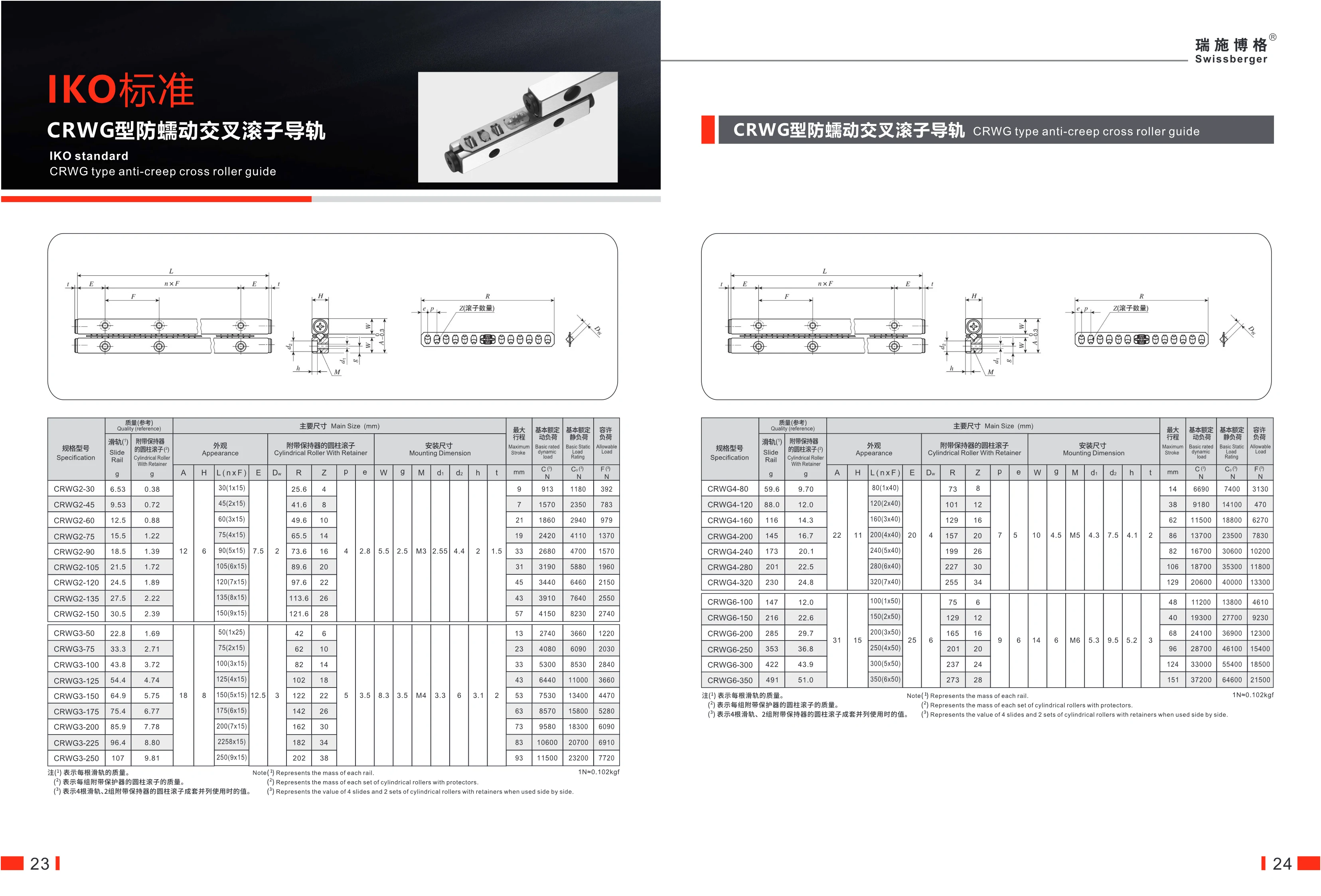
CRWG Anti-Creep Crossed Roller Guideway
The CRWG anti-creep crossed roller guideway is a high-rigidity linear motion component designed to IKO standards. Its crossed cylindrical rollers effectively prevent creeping at low speeds, ensuring smooth, stable linear motion. It is suitable for applications requiring high-precision positioning, including precision machine tools, semiconductor equipment, and medical devices. The guideways are available in widths of 4 mm and 6 mm, and lengths from 80 mm to 350 mm to suit different stroke requirements. Basic dynamic and static load ratings are provided to meet a range of load requirements.
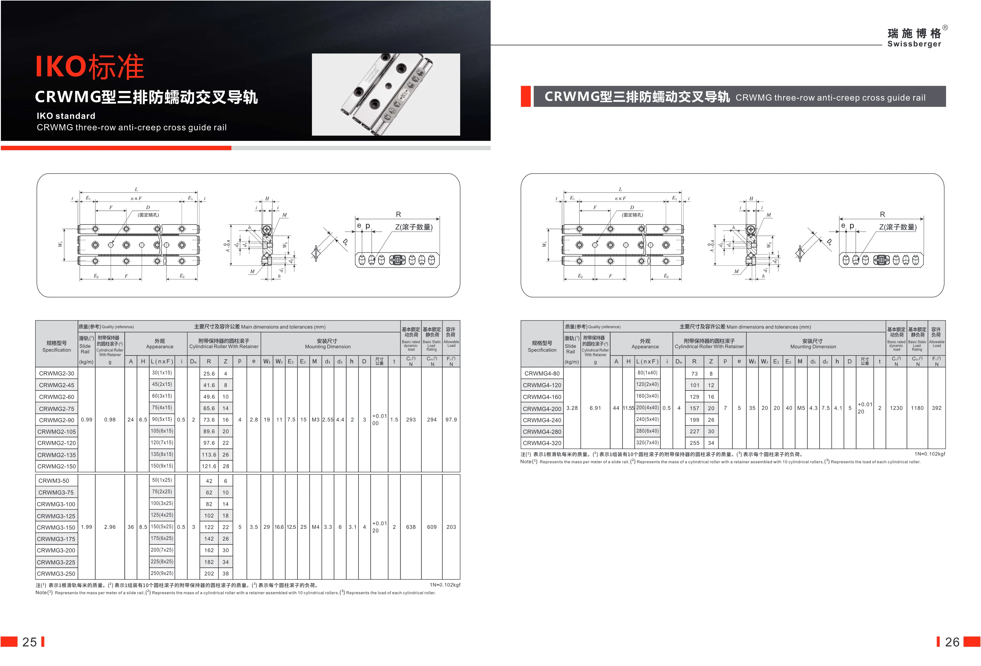
CRWMG Three-Row Anti-Creep Crossed Roller Guide
The CRWMG three-row anti-creep crossed roller guide is part of IKO’s standard product range. It features a three-row cylindrical roller design with anti-creep functionality, making it suitable for high-precision linear motion applications. The guide comes with side protectors and is available in various mounting dimensions. Its basic dynamic load rating starts at 1,230 N, its basic static load rating at 1,180 N, and its allowable load is 392 N. Models range from CRWMG4-80 to CRWMG4-320 in 40 mm length increments to accommodate different travel requirements. Its compact design and high rigidity make it widely used in automation equipment, machine tools, semiconductor equipment, and other fields.
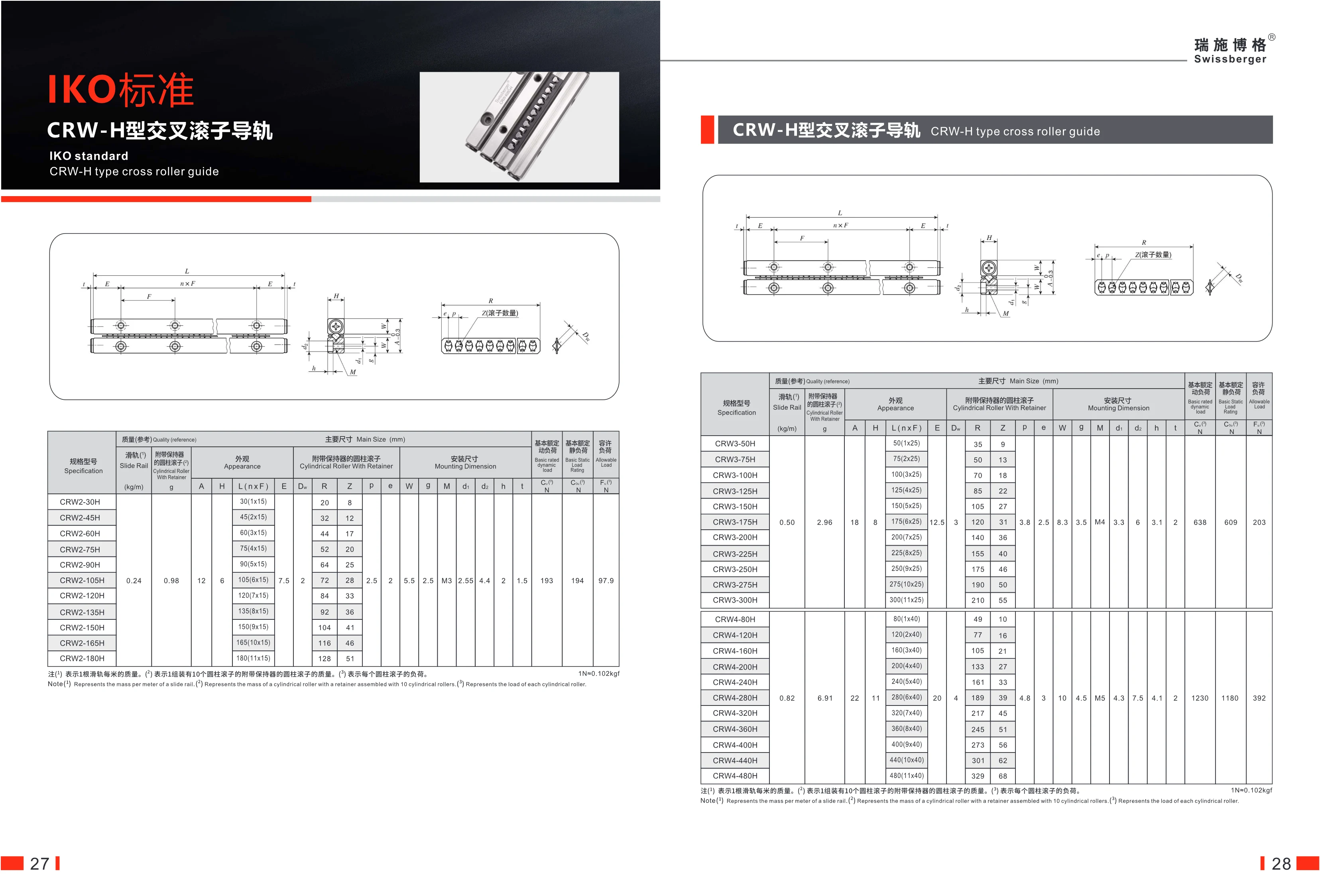
CRW-H Series Crossed Roller Guides and Slides
The CRW-H crossed roller guide is part of IKO’s standard product range. Its crossed-roller design, with rollers arranged alternately, provides high rigidity and precision. It is suitable for linear motion applications involving heavy loads and frequent reciprocating movement. The series comes in two basic sizes, CRW2 and CRW3, with guide lengths ranging from 30 mm to 300 mm to accommodate different stroke requirements. Mounting dimensions, rated loads, and other specifications vary by model. These guides are widely used in industrial automation equipment, precision machinery, measuring instruments, and other applications.
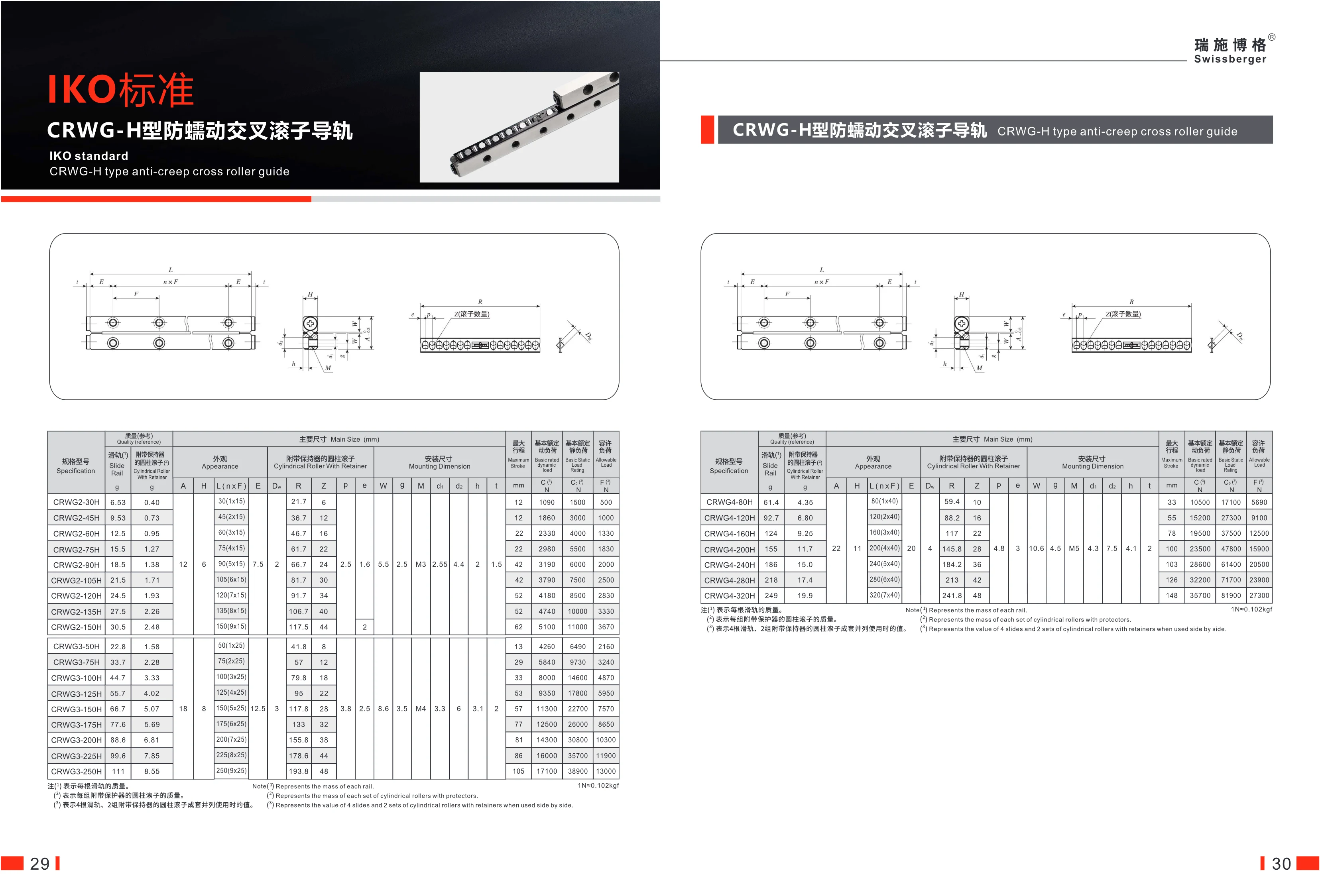
CRWG-H Anti-Creep Crossed Roller Guide
The CRWG-H Anti-Creep Crossed Roller Guide is a standard IKO product featuring cylindrical rollers arranged in a crossed pattern. Its anti-creep design offers high rigidity and precision, making it suitable for applications requiring precise positioning under heavy loads. It is available in a range of specifications, with rail lengths from 80 mm to 320 mm and maximum strokes from 59.4 mm to 241.8 mm. The basic dynamic load rating ranges from 10,500 to 35,700 N, the basic static load rating from 17,100 to 81,900 N, and the allowable load from 5,690 to 27,800 N. It has 1 to 7 roller groups (40 mm per group) to accommodate different stroke and load requirements.
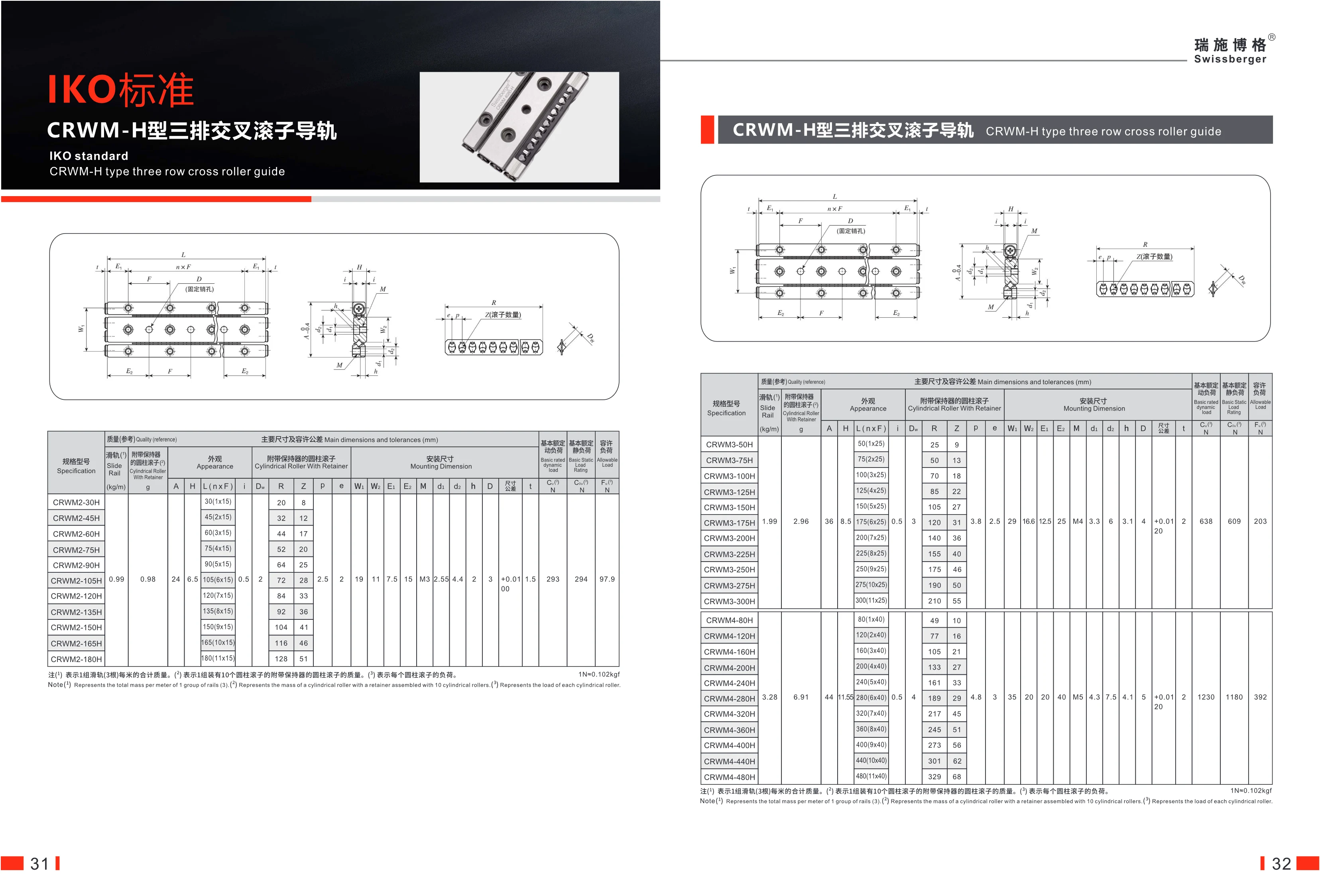
CRWM-H Three-Row Crossed Roller Guide
The IKO standard CRWM-H three-row crossed roller guide features a three-row crossed roller design that provides high rigidity, precision, and load capacity. It is suitable for precision linear motion applications subject to heavy loads and moments. The series is available in three width options—CRWM2, CRWM3, and CRWM4—with different cross-sectional dimensions. Lengths range from 30 mm to 500 mm, in increments of 15 mm, 25 mm, and 40 mm, respectively. Its high basic dynamic and static load ratings meet heavy-duty requirements. Standardized mounting dimensions make it easy to integrate into a variety of automation equipment. Caged cylindrical rollers reduce friction and extend service life. Suitable for precision machinery applications such as machine tools, industrial robots, and semiconductor equipment.

BK Series
The BK series consists of fixed-end support units for ball screws, featuring a high-rigidity design for axial positioning and support. Models range from BK10 to BK40, with supported shaft diameters (d1) from 10 mm to 40 mm and overall lengths (L) from 25 mm to 61 mm. Mounting dimensions include width (B), height (H), and bolt-hole spacing (P). The units comply with machine-tool industry standards and are interchangeable with products from international brands such as THK. Made from high-quality alloy steel and precision-machined, they deliver high accuracy and a long service life. They are widely used in CNC machine tools, automation equipment, industrial robots, and other applications requiring precision linear motion.
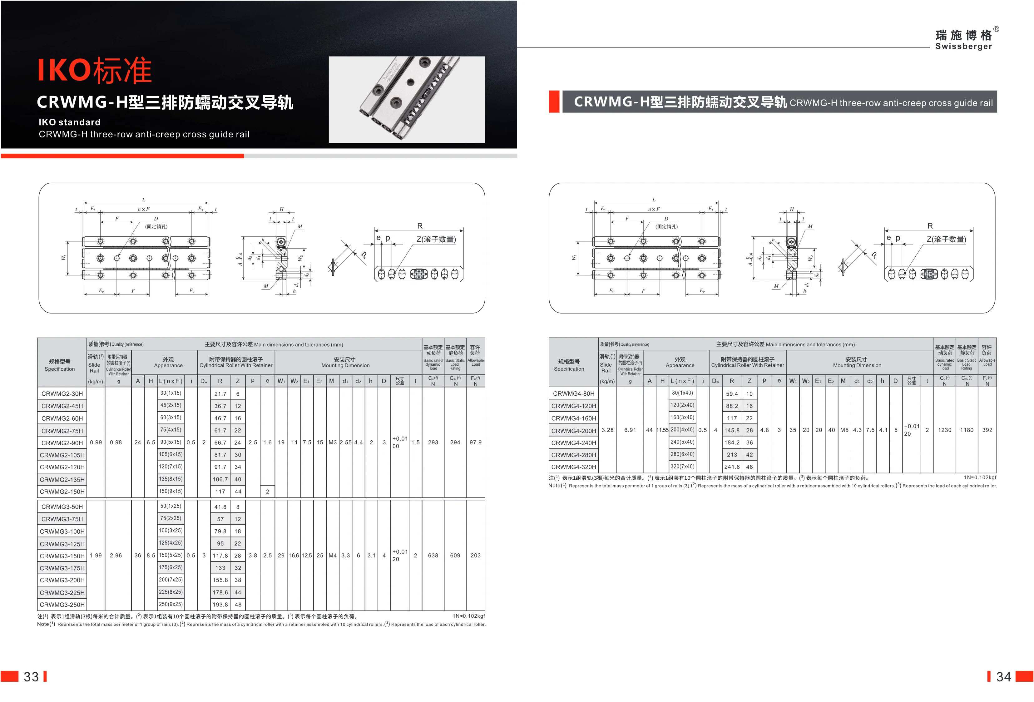
CRWMG-H Three-Row Anti-Creep Cross Roller Guide
This series of three-row anti-creep cross roller guides features an IKO standard design and anti-creep functionality, making it suitable for high-precision linear motion applications. Key specifications: available in Type 2 and Type 4 widths, with lengths ranging from 30 mm to 320 mm in increments of 15 mm or 40 mm. The guides offer high basic dynamic and static load ratings, high permissible loads, and precise mounting dimensions. The guide rail weighs 0.99 kg/m (Type 2) or 3.28 kg/m (Type 4). Each set includes three guide rails.
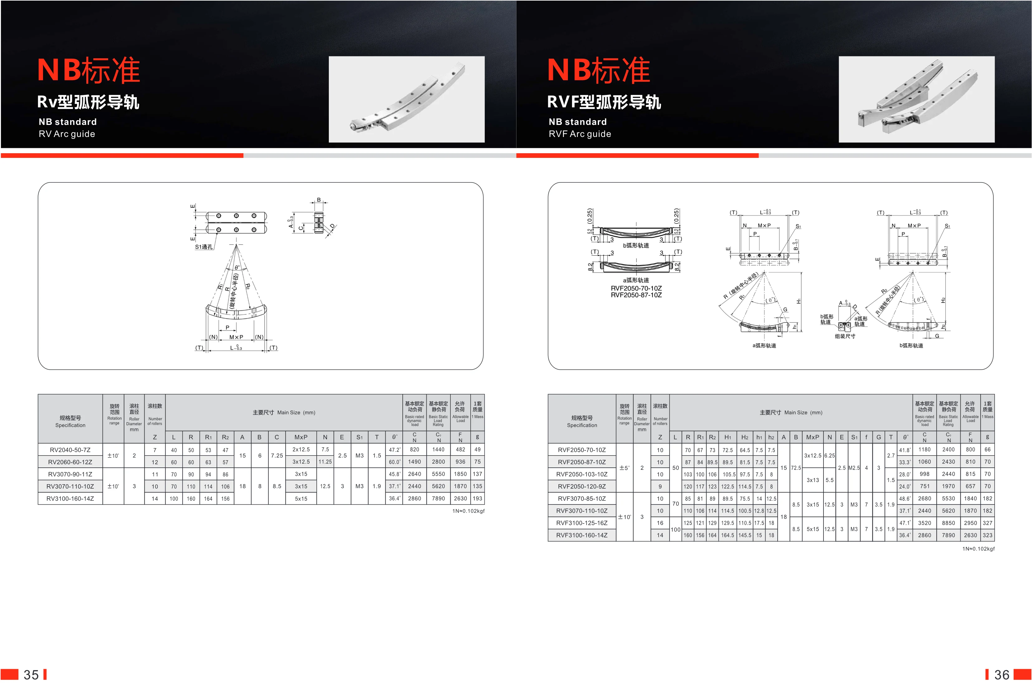
RVF Arc Guide
The RVF arc guide is a circular-motion guide component in the NB standard series. Its roller-based design delivers smooth arcuate movement. The series includes subseries such as RVF2050, RVF3070, and RVF3100, with roller diameters of 2 mm and 3 mm, rotation ranges of ±5° or ±10°, and roller counts ranging from 9 to 16. These products offer high rigidity and load capacity, making them suitable for circular-path motion in automation equipment, robots, and other applications. Key dimensions can be customized to meet different installation requirements.
RV Series Curved Guideway
The NB-standard RV Series curved guideway uses roller rolling elements and is designed for high-rigidity, high-precision arc motion. Available in RV and RVF types, it offers a rotation range of ±5° or ±10°, roller diameters of 2 mm or 3 mm, and model-dependent roller counts. Basic dynamic load ratings range from 820 N to 2,860 N, basic static load ratings from 1,440 N to 7,890 N, and allowable loads from 482 N to 2,630 N. Lightweight and compact, it complies with NB standards and is widely used in automation equipment, machining, and other applications.
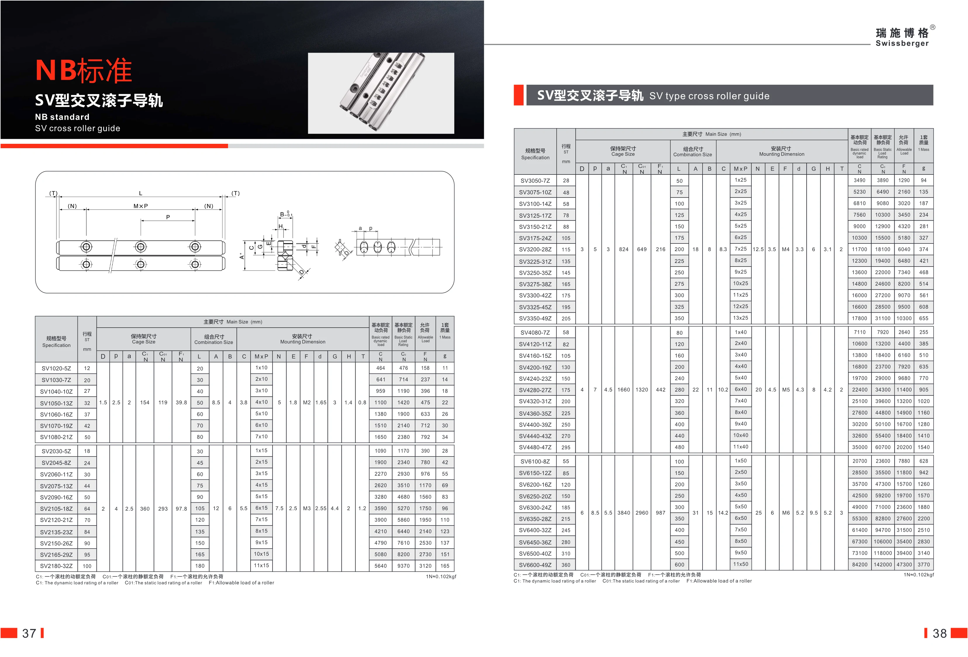
SV-Type Crossed Roller Guide
NB standard SV-type crossed roller guides are high-rigidity, high-precision linear motion guide components. They use staggered rollers as rolling elements and can support loads in all directions. The series includes standard SV and H-type (high-load) models in a wide range of sizes, making them suitable for automation equipment, machine tools, semiconductor equipment, and other applications requiring high load capacity and precision positioning. Specifications include stroke, number of rollers, cage dimensions, combined dimensions, mounting dimensions, basic dynamic load rating, basic static load rating, and permissible load. Strokes range from 12 mm to 720 mm, and the number of rollers varies by model.
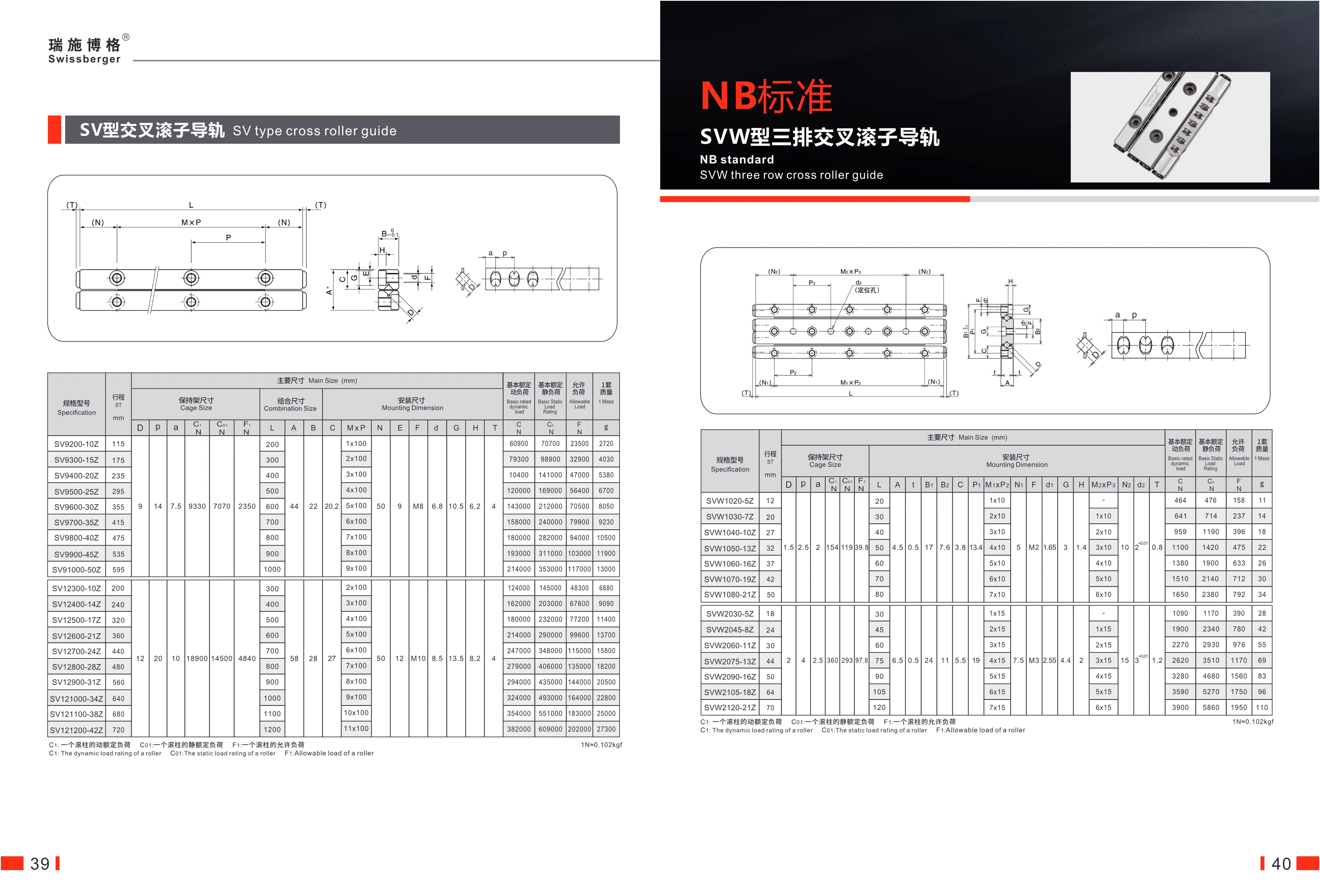
SVW Triple-Row Crossed Roller Guide
The SVW triple-row crossed roller guide is designed to NB standards and features a three-row crossed roller arrangement. It offers high rigidity, precision, and load capacity, making it suitable for linear motion applications that require a compact installation space and the ability to handle heavy loads. With strokes ranging from 12 mm to 70 mm and a variety of models available, it features high dynamic and static load ratings and is ideal for automation equipment, machine tools, semiconductor equipment, and other applications.
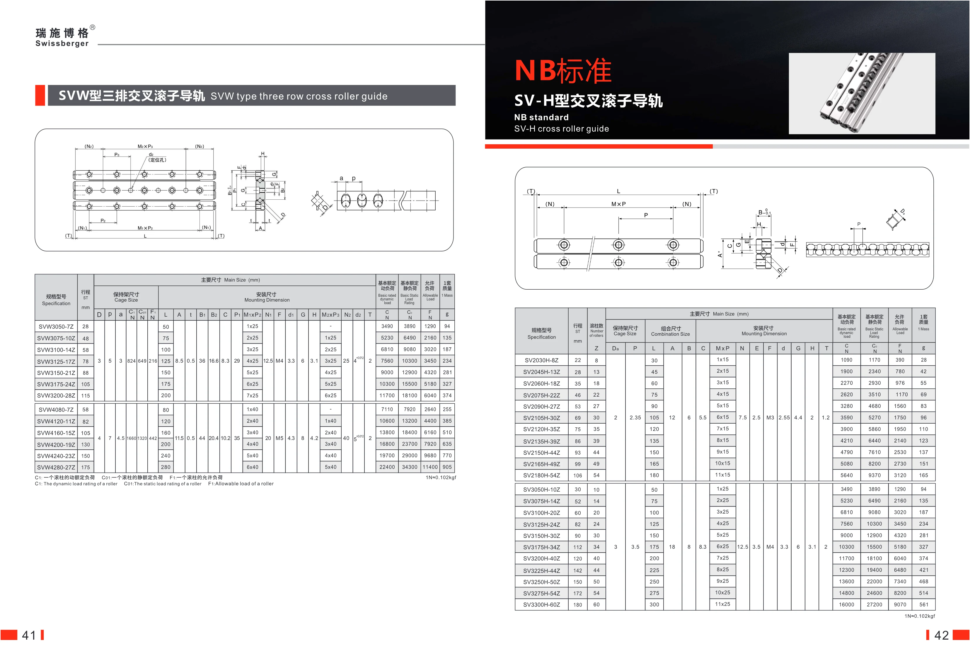
SV-H Crossed Roller Guideway
The SV-H crossed roller guideway is a high-precision linear motion component that uses alternately arranged rollers as rolling elements. It offers high rigidity, high precision, and low friction. The series is available in a range of sizes, with strokes from 22 mm to 180 mm and roller counts from 8 to 60. It has a basic dynamic load rating of up to 16,000 N, a basic static load rating of up to 27,200 N, and an allowable load of up to 9,070 N. It is suitable for applications requiring precise positioning, such as automation equipment, machine tools, and precision instruments. The guideway is made of high-quality bearing steel and features 2.35 mm diameter rollers with a hardened surface for excellent wear resistance.
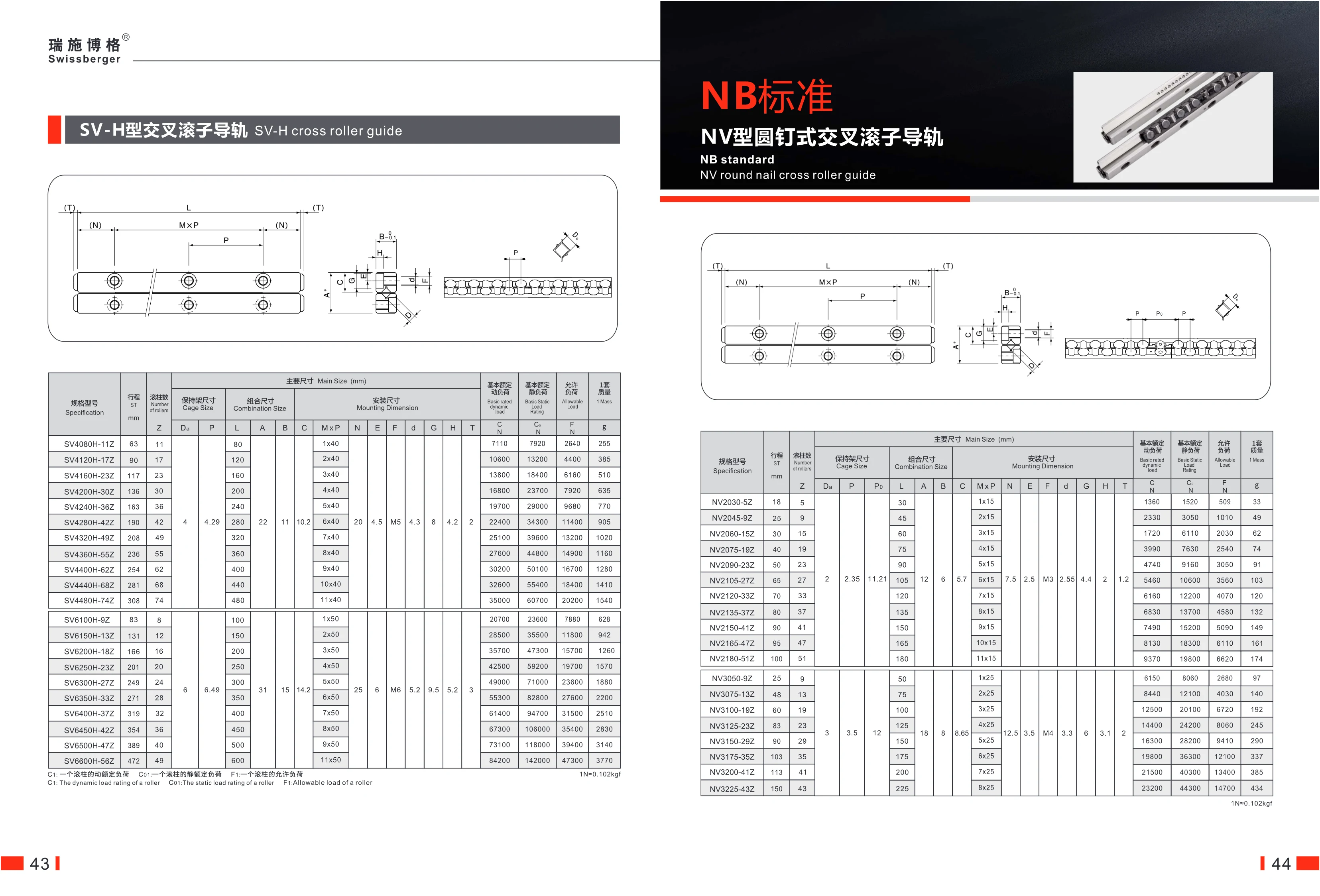
NV-Type Round-Pin Crossed Roller Guideway
The NV-type round-pin crossed roller guideway features a crossed cylindrical roller arrangement for highly rigid, high-precision linear motion. It is suitable for precision positioning and heavy-duty applications. Available in a range of sizes, it offers strokes of 18–275 mm and 5–74 rollers, with basic dynamic load ratings of up to 104,000 N and static load ratings of up to 187,000 N. Models range from NV030-52 to NV6400-39Z; different suffixes indicate different sizes and load ratings to suit a variety of applications.
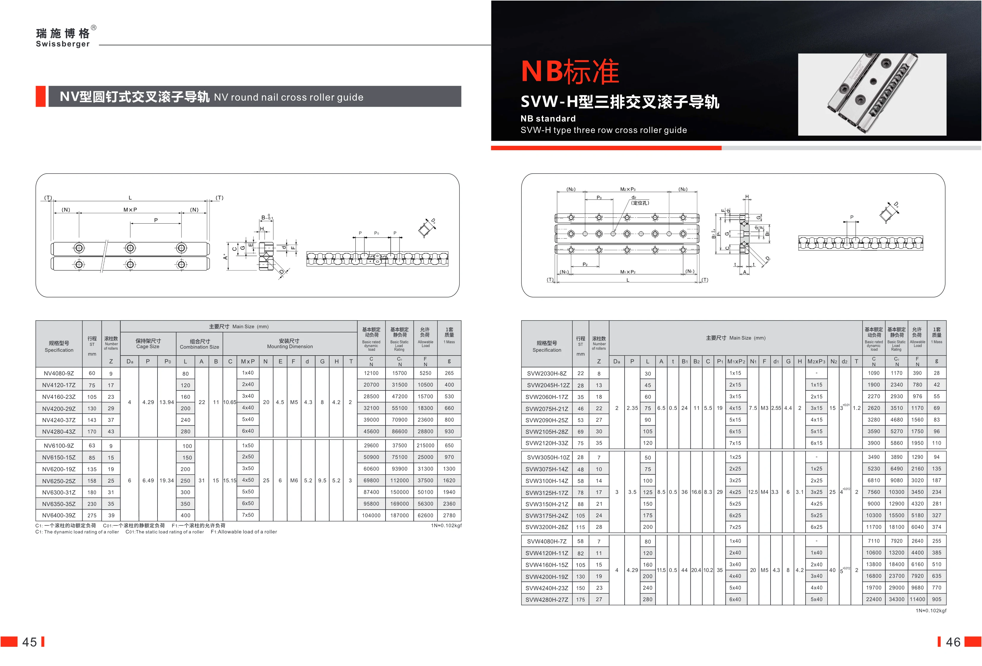
SVW-H Three-Row Crossed Roller Guideway
The SVW-H three-row crossed roller guideway meets NB standards. Its three rows of cylindrical rollers are arranged in a crossed configuration to deliver high rigidity and precise linear motion. It is suitable for precision equipment subject to loads from multiple directions, such as machine tools and automated assembly lines. Model SVW2030H-8Z has a 22 mm stroke and 8 rollers, with a compact design and excellent load capacity.
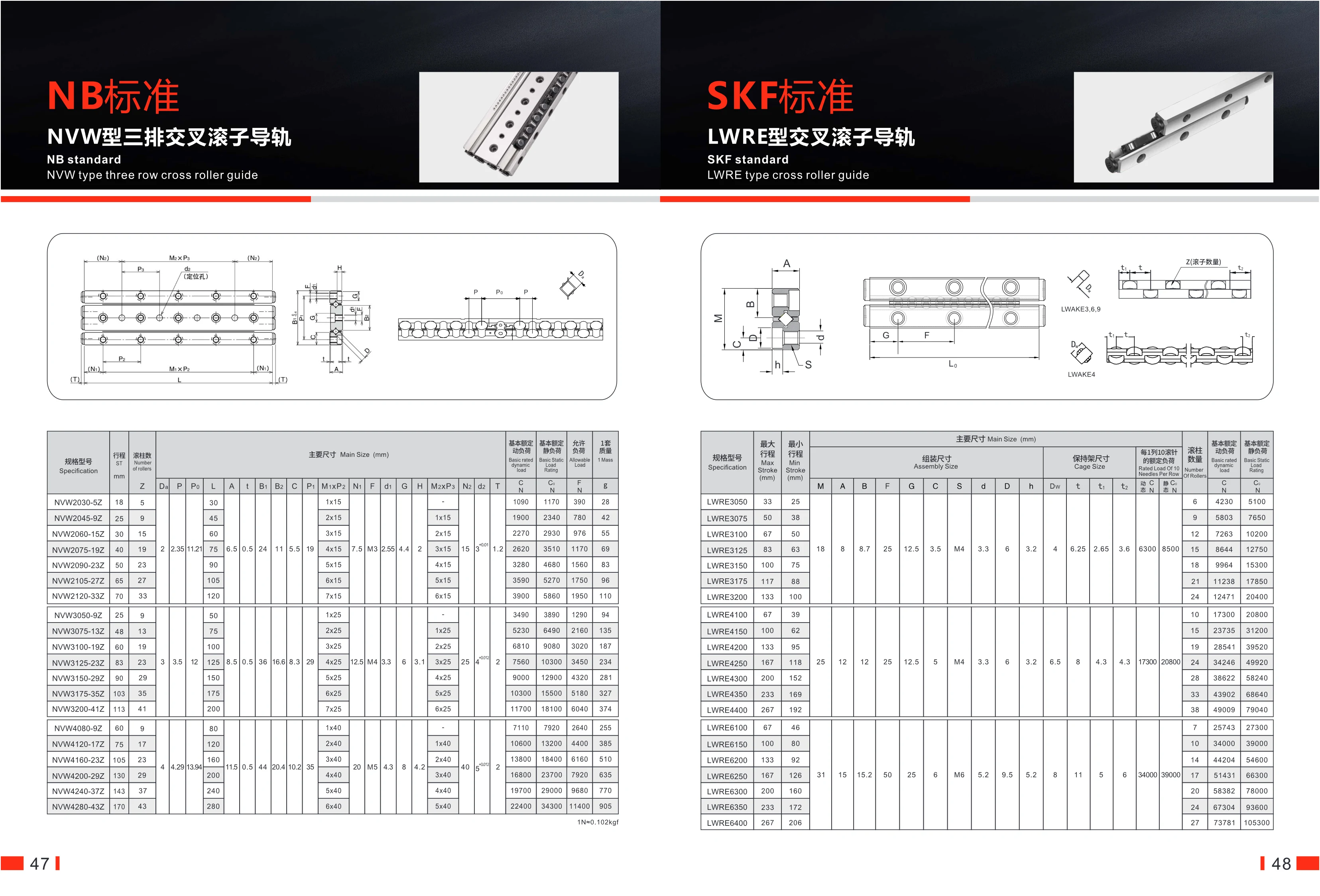
NVW Three-Row Crossed Roller Guideway
The NVW three-row crossed roller guideway is a high-precision linear motion component built to NB standards. Its three rows of crossed rollers support loads from multiple directions, making it suitable for automated equipment requiring high rigidity and precision. The series is available in three guideway widths—20 mm, 30 mm, and 40 mm—with a range of length and roller-count combinations for each width. Key dimensions include guideway length and mounting-hole spacing. The basic dynamic load rating ranges from 1,900 to 7,110 N, the static load rating from 1,170 to 9,080 N, and the allowable load from 390 to 3,020 N. Weight per set ranges from 28 to 255 kg. Stroke ranges from 18 to 170 mm, with 5 to 43 rollers. These products are widely used in machine tools, semiconductor equipment, industrial robots, and other applications.
LWR Crossed Roller Guideways
LWR crossed roller guideways are precision linear motion components manufactured to SKF standards. Their crossed roller arrangement provides high load capacity, excellent rigidity and smooth movement. Available in a range of sizes from LWR3050 to LWR6400, this series is suited to applications in automated equipment that require high-precision positioning and heavy-load transfer. The rollers make line contact with the guideway surfaces, resulting in low friction and long service life. They are also easy to install. The optional anti-creep LWRECAS series is suitable for vertical or inclined mounting.

EF-Type Support Unit
The EF series consists of floating-end support units for ball screws. They support the end of the screw while allowing axial movement to compensate for thermal expansion and installation errors. Models include EF6, EF8, EF10, EF12, EF15, and EF20, each designed for a different bearing-seat shaft diameter. Their compact design makes them easy to install and suitable for a wide range of automation equipment. Complete dimensional specifications are available, including bearing-seat shaft diameter (mm), length, width, height, and mounting-hole spacing. Made from high-quality steel with a rust-resistant surface treatment.
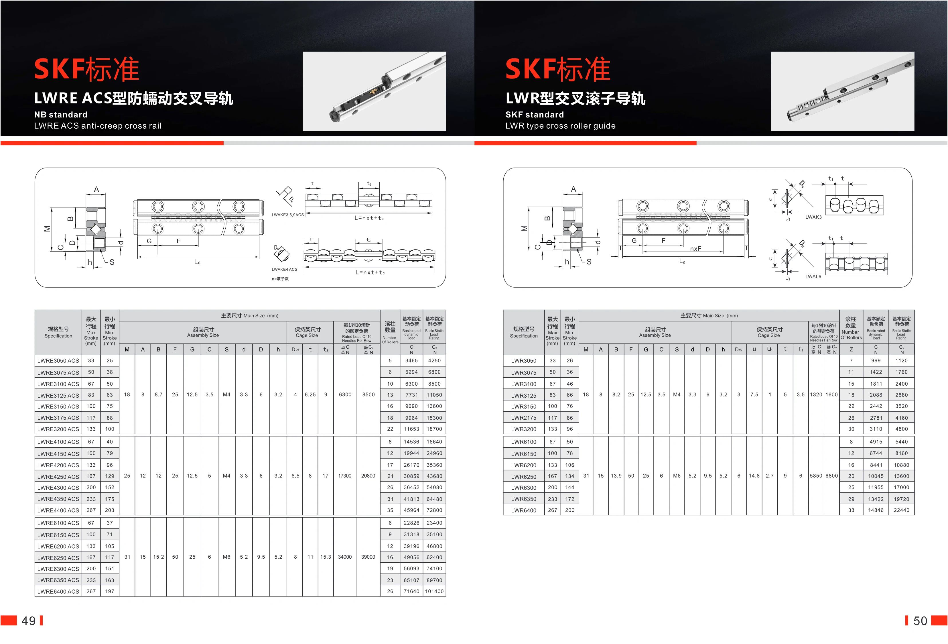
LWRECAS Anti-Creep Crossed Roller Guide
The LWRECAS anti-creep crossed roller guide is designed to SKF standards and features an anti-creep mechanism that prevents the rollers from shifting during operation. It is suitable for high-precision linear motion applications. Its compact structure and high rigidity deliver stable, reliable guidance.
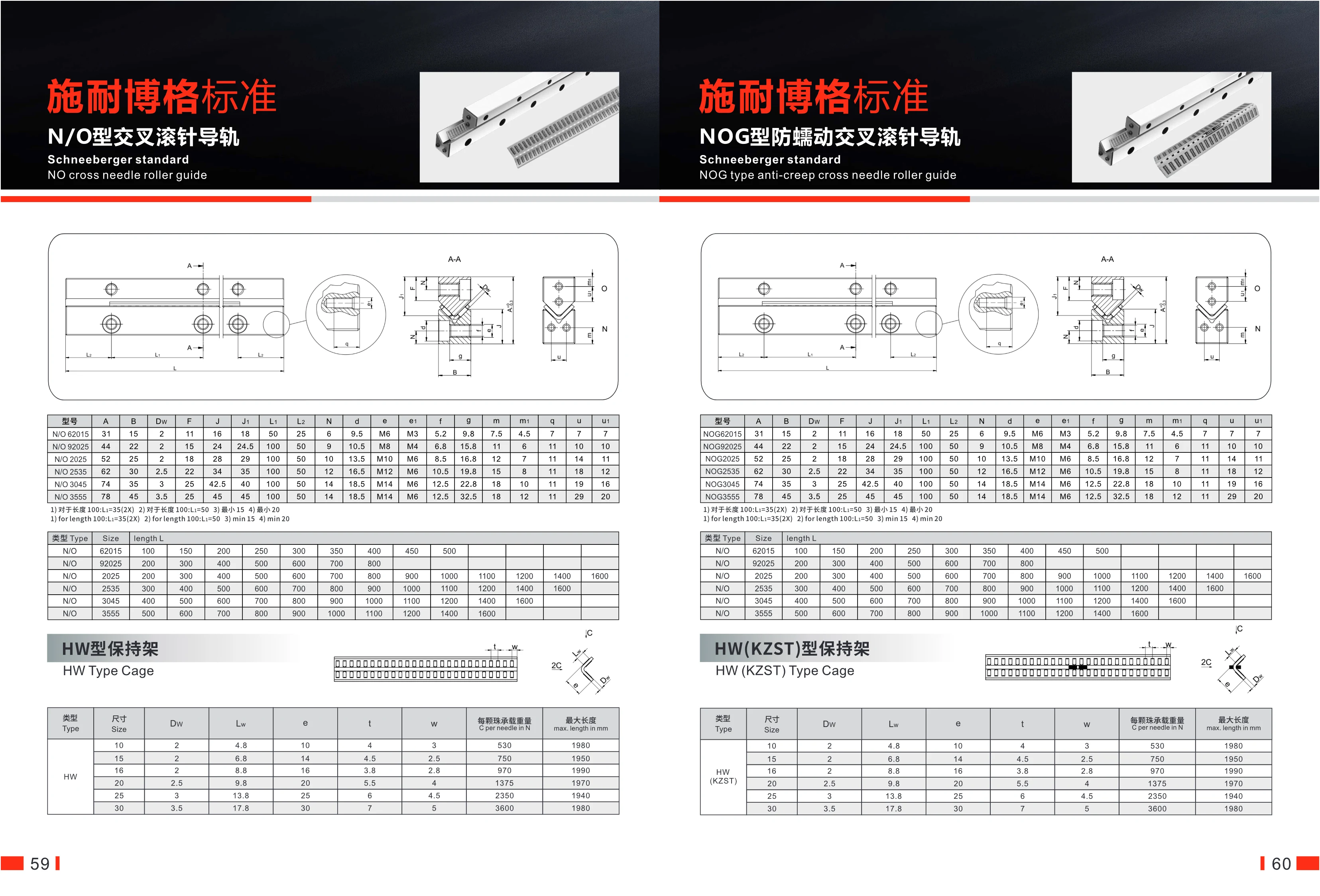
Schneeberger N/O and NOG Crossed Needle Roller Guideways
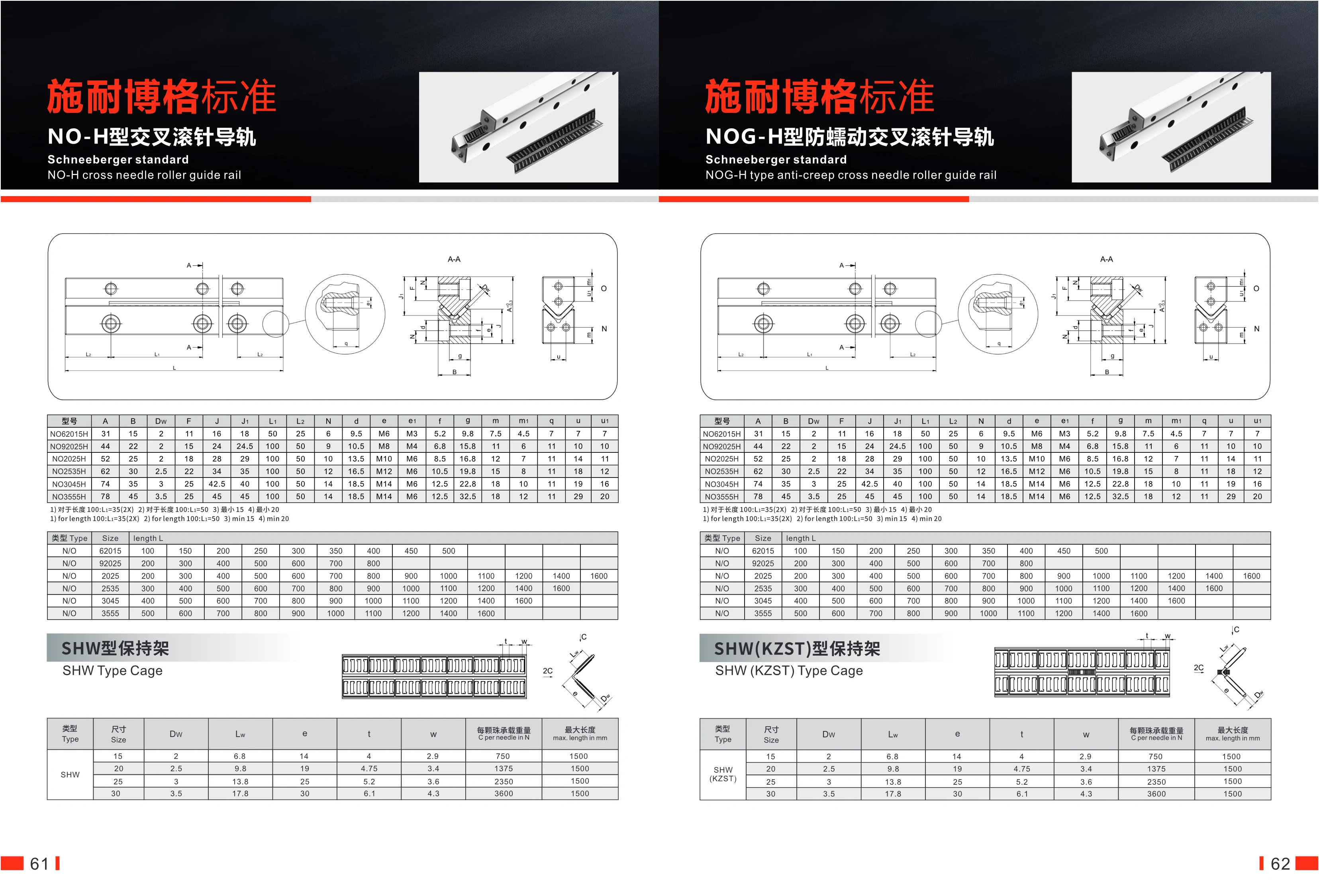
This series comprises Schneeberger standard N/O crossed needle roller guideways and NOG anti-creep crossed needle roller guideways. The crossed needle roller arrangement provides high rigidity and load capacity. The N/O is the standard type, while the NOG features an anti-creep design for precision positioning and high-speed motion. Guideway cross-section widths range from 31 to 78 mm, heights from 15 to 45 mm, and needle roller diameters from 2 to 3.5 mm. A wide range of lengths is available, up to 1,600 mm. Compatible with HW-type cages, the needle rollers have load capacities of 530–3,600 N each. These guideways are widely used in automation equipment, machine tools, semiconductor equipment, and other applications requiring precise linear motion.
NOG anti-creep crossed needle roller guideways
NOG anti-creep crossed needle roller guideways are standard SCHNEEBERGER products. Their crossed needle roller arrangement provides anti-creep performance, making them suitable for high-precision, high-rigidity linear motion applications. The guideways are made of hardened steel and use needle rollers with diameters from 2 mm to 3.5 mm. Width A ranges from 31 mm to 78 mm, and height B from 15 mm to 45 mm. A range of sizes is available: 62015, 92025, 22025, 23525, 3045 and 3555, each in multiple standard lengths from 100 mm to 1,400 mm. Precision mounting holes are provided, and an HW-type cage is available as an option. These guideways are suitable for machine tools, automation equipment, precision measuring instruments and other applications requiring backlash-free, low-friction linear guidance.
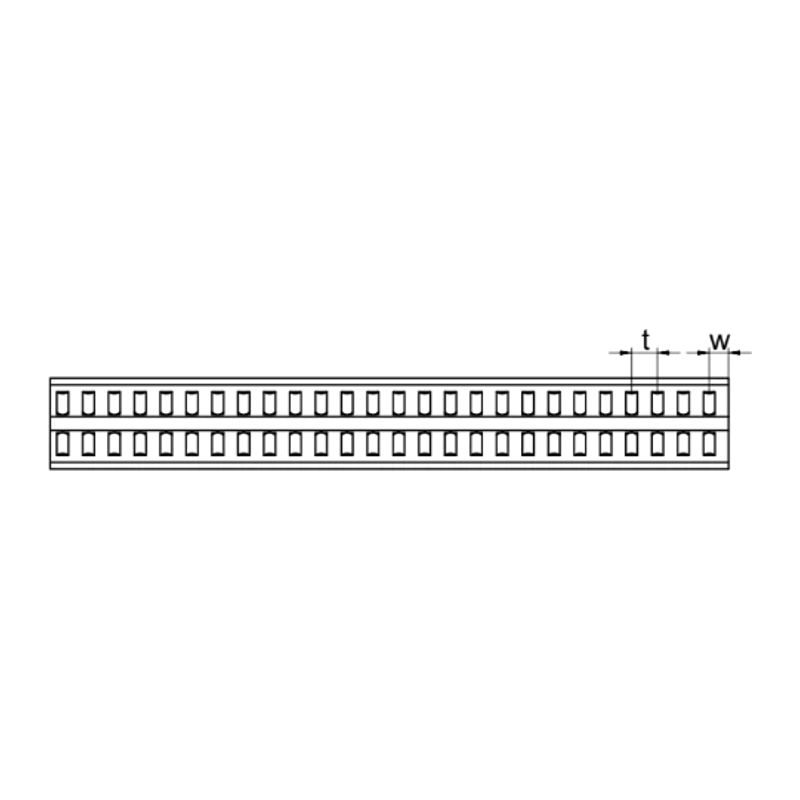
Schneeberger HW-Type Cage
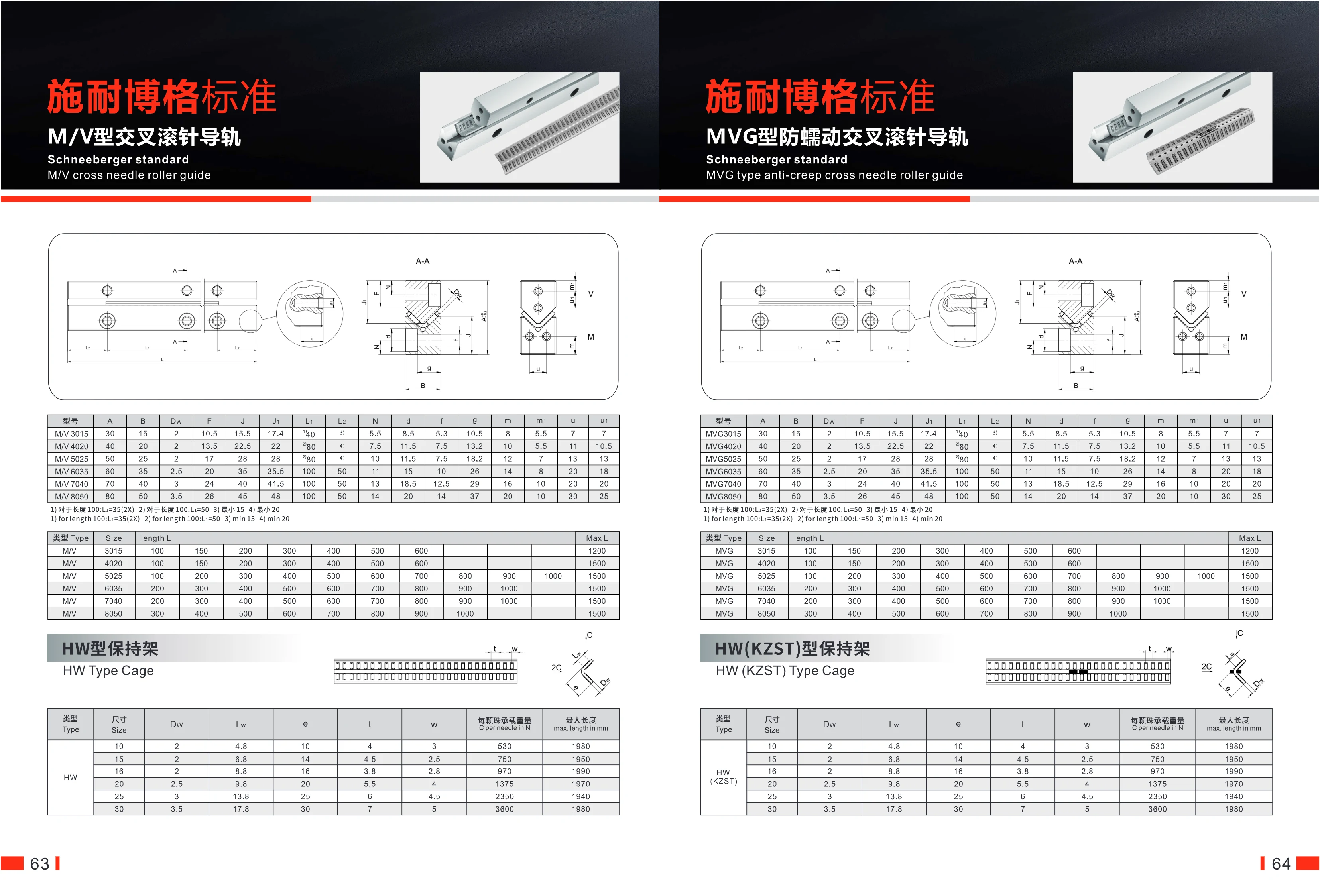
The HW-type cage is an essential component of Schneeberger standard crossed-roller guideway systems and is suitable for N/O-type and NOG-type guideways. Made from high-strength engineering plastic or metal, it offers high rigidity, low friction, and excellent wear resistance. It is available in six sizes (10, 15, 16, 20, 25, and 30) for different needle roller specifications (Dw from 2 mm to 3.5 mm). Load capacity per needle roller ranges from 530 N to 3,600 N, and the maximum length is 1,990 mm. The cage spacing (e) and widths (t, w) are precisely designed to ensure even roller distribution and stable operation. Widely used in precision positioning, heavy-load handling, and automation equipment, it effectively prevents creeping and improves motion accuracy and service life.
NO-H Crossed Roller Guideway
The NO-H Crossed Roller Guideway is part of SCHNEEBERGER’s standard range. It uses cylindrical rollers arranged alternately to provide high rigidity and precision linear motion. It is suitable for automation equipment requiring heavy-load capacity, high rigidity and high precision, such as machine tools, robots and semiconductor equipment. A range of cross-sectional sizes is available (A: 31–78 mm, B: 15–45 mm, roller diameter: 2–3.5 mm), with custom lengths available on request. The guideways and roller cages can be separated for easy installation and maintenance. The model designation follows the format NO + size + height + H, for example, NO62015H.
NOG-H Anti-Creep Crossed Needle Roller Guide Rail
The standard NOG-H anti-creep crossed needle roller guide rail from ShineTop features a crossed-roller design with anti-creep functionality, making it suitable for high-precision linear motion applications. It is available in several sizes: NO62015H, NO92025H, NO225H, NO235H, NO3045H and NO3555H. Each size has different width (A), height (B) and needle diameter (Dw) dimensions. Rail lengths can be selected to suit requirements, ranging from 200 mm to 600 mm, with common increments of 50 mm or 100 mm. This series offers high rigidity and load capacity, with standardized mounting dimensions for easy replacement. Needle diameters range from 2 mm to 3.5 mm, widths from 31 mm to 78 mm, and heights from 15 mm to 45 mm to accommodate different load and space requirements. Suitable for automation equipment, machine tools, precision machinery and more.
SHW Series Crossed Roller Guides
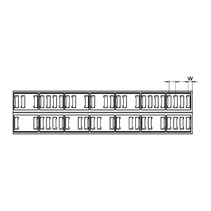
This series comprises Schneeberger standard crossed roller guides and SHW-type cages, including standard NO-H, anti-creep NOG-H, MV-H, and MVG-H types. Roller diameters range from 2 mm to 3.5 mm, guide widths from 15 mm to 50 mm, and lengths from 100 mm to 1,500 mm (standard lengths: 100–600 mm; maximum length: 1,500 mm). SHW cages are available in four sizes—15, 20, 25, and 30—corresponding to roller diameters of 2–3.5 mm. Load capacity per roller ranges from 750 N to 3,600 N. These products offer high rigidity, low friction, and high precision, making them suitable for precision linear motion applications in automation equipment, machine tools, semiconductor equipment, and more.
SCHNEEBERGER Standard M/V Crossed Needle Roller Guideways
SCHNEEBERGER Standard M/V crossed needle roller guideways are high-precision linear guidance components consisting of guideways and cages. They are designed for applications requiring low friction, high rigidity, and high load capacity. The guideways use a crossed needle roller design, with rollers arranged alternately to support loads in both directions. The range includes standard M/V models and anti-creep MVG models, which differ slightly in their dimensions. The MVG models use a specially designed cage to prevent roller creep. Guideway sizes range from 3015 to 8050, with several lengths available up to 1,500 mm. HW-type cages are available in sizes 10 to 30 and can be ordered separately. These products are widely used in precision machinery, including semiconductor equipment, machine tools, and measuring instruments.
MVG anti-creep crossed needle roller guideway
The MVG anti-creep crossed needle roller guideway is a standard Shinaibo product. Its crossed needle roller design prevents creeping, making it suitable for high-precision, high-rigidity linear motion applications. Available in a range of sizes, including MVG3015, MVG4020, MVG5025, MVG6035, MVG7040 and MVG8050, each model has its own cross-sectional dimensions (A, B, Dw, etc.) and length range (100 mm to 1,500 mm). Needle roller diameters range from 2 mm to 3.5 mm, providing high load capacity. The HW (KZST) cage keeps the needle rollers evenly spaced. These guideways are widely used in machine tools, automation equipment and precision instruments, and offer low friction, long service life and easy installation.
MV-H Crossed Needle Roller Guideway
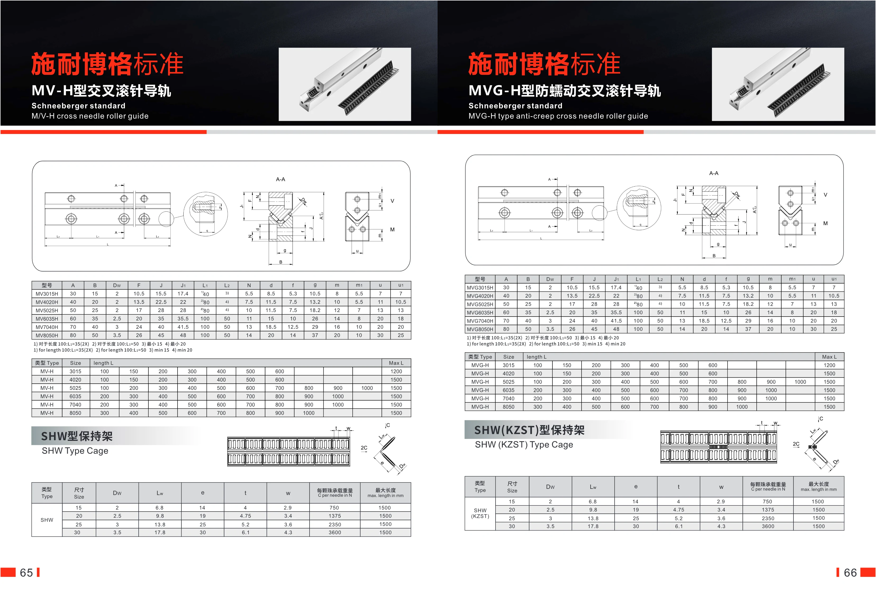
The MV-H crossed needle roller guideway is designed to the Schneberger standard, with needle rollers arranged crosswise to provide high rigidity and precision. It is suitable for precision machinery, machine tools, automation equipment, and more. The guideway is 30–80 mm wide and 15–50 mm high, with roller diameters of 2–3.5 mm. Standard lengths range from 100 to 600 mm, with a maximum length of 1,500 mm. The matching SHW cage ensures even roller distribution and reduces friction. For detailed dimensions such as mounting-hole spacing and counterbores, see the specification table.
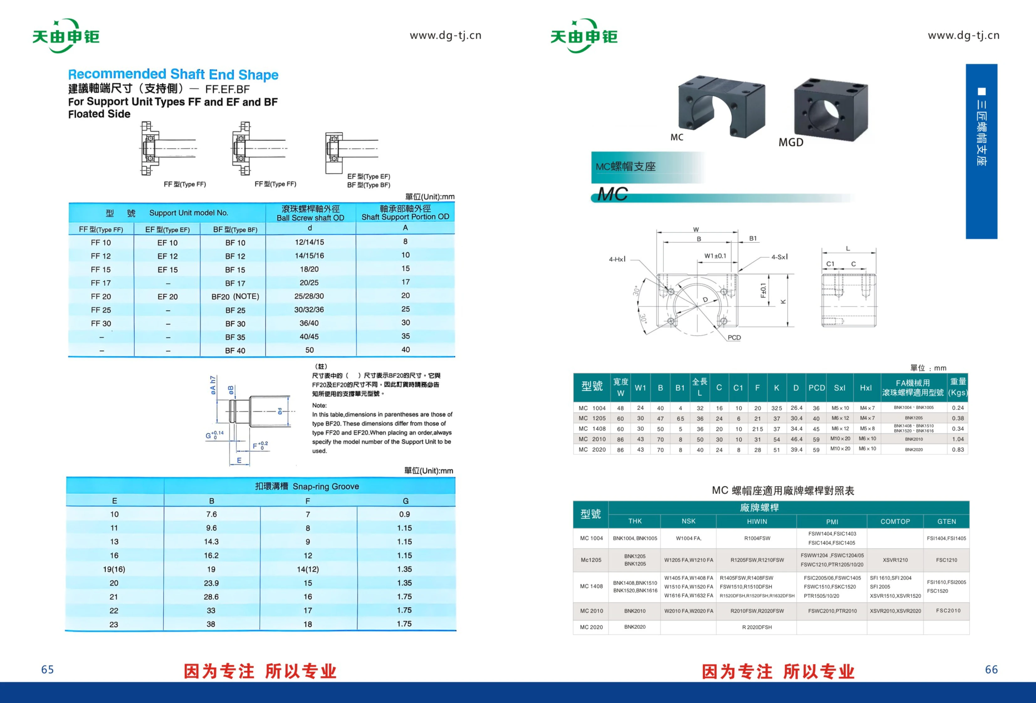
BF Series Support Units
BF series support units are used to provide floating-end support for ball screw shafts and are available in FF, EF, and BF configurations. The series includes nine models, from BF10 to BF40, to accommodate different ball screw shaft diameters (d) and bearing-section shaft diameters (A). See the table for dimensions. The BF20 differs in size from the FF20/EF20, so please specify the model when ordering.
MVG-H Anti-Creep Crossed Needle Roller Guideway
The MVG-H series comprises SCHNEEBERGER standard anti-creep crossed needle roller guideways. Their crossed-needle design prevents creep, making them suitable for high-precision, high-rigidity linear motion applications. Six sizes are available: 3015, 4020, 5025, 6035, 7040 and 8050. Widths range from 30 mm to 80 mm, heights from 15 mm to 50 mm, and needle roller diameters from 2 mm to 3.5 mm. Depending on the size, lengths range from 100 mm to 1,500 mm. The guideways are compatible with SHW (KZST) cages, with needle roller diameters of 2 mm to 3.5 mm and high load capacity of 750–3,600 N per needle roller. They are suitable for machine tools, industrial automation, precision instruments and other applications.

MC Series Support Unit
MC Series support units are precision components designed to support the shaft ends of ball screws. Compatible with BNK Series ball screws, they provide stable axial and radial support. The series includes models such as MC1004, MC1205, MC1408, MC2010, and MC2020, with widths ranging from 48 to 86 mm, lengths from 4 to 65 mm, and weights from 0.24 to 1.04 kg. Each model is designed for a specific screw diameter and mounting dimensions. Made from high-quality materials, these units are widely used in factory automation equipment, machine tools, and other FA machinery. Specifications include width W, B, B1, overall length L, C, C1, F, K, D, and PCD. Mounting hole specifications are SxI and HxI. Choose a suitable model based on the screw type and available mounting space.
FLBX40 Series
This page provides dimensional drawings for the FLBX40 series, listing three models/configurations: FLBX40-C, FLBX40-L, and FLBX40-R. The catalog does not specify material, travel, accuracy, load capacity, or other parameters. When selecting a model, consult the corresponding dimensional drawing to confirm the mounting interface and overall dimensions. This series is intended for component selection in factory automation equipment. Refer to the complete catalog and drawings for detailed specifications.
FLBX60/FLBY60 Series Manual Translation Stages
The FLBX60/FLBY60 series consists of manual precision translation stages with SUS440C stainless steel bodies, micrometer head drives, and 60mm×60mm platforms. FLBX60 provides movement along the X axis, while FLBY60 provides movement along both X and Y axes. All models have a travel range of ±6.5mm, a load capacity of 196N(20kgf), a minimum scale division of 0.01mm, and a travel parallelism of ≤0.005mm/13mm. The FLBX60-C has a platform thickness of 15mm, a parallelism of 0.02mm, and a weight of 0.4kg; all other models have a platform thickness of 30mm, a parallelism of 0.04mm, and a weight of 0.8kg. Model suffixes include C/L/R. The stages are suitable for optical, inspection, and precision positioning applications.
FLBX60/FLBY60 Series Linear Modules
The FLBX60/FLBY60 series is a range of size 60 linear modules from FARAY AUTOMATION. The catalog page provides dimensional drawings for four basic configurations, distinguished by mounting/structural arrangement and travel: FLBX60-C, FLBY60-C, FLBX60-L, and FLBY60-L. FLBX60 and FLBY60 are two alternative carriage/guide rail arrangements, while C and L denote two length (travel) variants of each arrangement. Select a model based on the load, travel, and available mounting space. Refer to the corresponding dimensional drawing for overall length, carriage mounting hole positions, travel, height, and other dimensions, and check for interference with the host assembly, coupling/motor mount, and cable carrier before ordering. This page contains dimensional drawings only; refer to the series specification page for repeatability, maximum speed, allowable load moments, motor configurations, and other specifications.
FLBX80 Series
The FLBX80 series consists of components for factory automation equipment. This page provides outline dimension drawings. The series includes two types, FLBX80 and FLBY80, each available in -C, -L, and -R variants, for a total of 6 models. This catalog page only shows outline dimensions and corresponding models; it does not list technical specifications such as material, accuracy grade, or rated load. For model selection, consult the dimension and specification tables in the complete catalog.
FLBY80 Series Linear Modules
The FLBY80 series consists of linear module bodies (single-axis slides) for factory automation. The catalog lists two orientation codes, FLBX80 and FLBY80, each available in C, L, and R variants. These typically indicate the mounting position of the motor or drive end (center, left, or right) or differences in structural orientation. This page provides only dimensional drawings for checking the outline, mounting surfaces, and interface locations of each variant. Specific technical parameters such as effective stroke, lead, repeatability, rated load, allowable moment, and maximum speed are not listed; consult the specification tables on other pages for the same series when selecting a model. The known model structure is “FLB + orientation letter (X/Y) + 80 + mounting variant (C/L/R).” For a non-standard stroke or special mounting arrangement, specify the complete model number along with the stroke and accessory sections when ordering.
FLGX40 Series Linear Modules
The FLGX40 series is available in three configurations: C, L and R (FLGX40-C, FLGX40-L and FLGX40-R). The catalog provides outline drawings showing the overall profiles and mounting dimensions of each configuration for use in product selection and equipment design. All three configurations share the same basic specifications but differ in their arrangement (centered, left-facing or right-facing), allowing flexible selection based on motor, cable outlet or mounting surface orientation where installation space is limited. Different configurations can also be used at different stations on the same machine. When selecting a module, refer to the dimensional drawing for the relevant configuration to verify mounting hole locations, overall height and width, and the interface with the driven component. Allow sufficient space for travel and clearance. This page contains dimensional drawings only and does not list performance parameters such as rated load, travel or accuracy grade. Consult the series specification page before making a final selection.
FLGX60 Series Manual Translation Stages
FLGX60 series manual translation stages feature a 60mm×60mm platform, ±6.5mm travel, a minimum scale increment of 0.01mm, and a rated load of 39.2N (4kgf) for precise manual movement and positioning. Two configurations are available: single-axis X (20mm platform thickness, 0.03mm parallelism, 0.21kg weight) and two-axis XY (40mm platform thickness, 0.06mm parallelism, 0.42kg weight). Travel parallelism is ≤0.02mm/13mm. The model suffixes C/L/R indicate different mounting and operating positions, allowing for multi-axis combinations and installation in confined spaces. Applications include optical component adjustment, inspection fixtures, and precision positioning in laboratories.
FLGX60 Series Linear Modules
The FLGX60 series is a size 60 linear motion module/linear slide offered by FARAY AUTOMATION. The catalog provides dimensional drawings for three configurations: FLGX60-C, FLGX60-L and FLGX60-R. C/L/R generally distinguish the mounting orientation or cable outlet/interface position (center, left-facing and right-facing). All three share the same external profile and mounting dimension references. Select the C/L/R variant based on available space and cable routing. The remaining cross-sectional dimensions, effective stroke and mounting hole locations are common to the same size. Refer to the complete catalog specifications and dimensional drawings for the effective stroke, lead, repeatability, rated load and other parameters.
FLS125 Series XYθ Multi-Axis Combination Stages
The FLS125 series consists of FARAY® manual multi-axis combination stages that stack an XY translation stage with a θ-axis rotation stage for precise adjustment along all three axes. The stage has a Φ125mm diameter platform and an aluminum alloy body with a black anodized finish. It is driven by micrometer heads with a minimum scale graduation of 0.01mm. XY travel is ±12.5mm, while the θ axis offers 360° coarse adjustment and ±5° fine adjustment. Load capacity is 49N (5kgf). The series includes the FLS125-LM and FLSP125-LM models, weighing 2.42kg and 2.72kg respectively. They are suitable for aligning samples and fixtures in optical lens, laser path, semiconductor inspection, and precision measurement applications. Select a model based on load capacity (≤5kgf), platform size, and whether θ-axis fine adjustment is required. During setup, lock each axis before adjusting the next to ensure repeatable positioning accuracy.
FLT125-LM-2/FLTP125-LM-2 Three-Axis Translation Stages
The FLT125-LM-2 and FLTP125-LM-2 are manual three-axis (XYZ) translation stages with black-anodized aluminum alloy bodies and micrometer head drives for smooth, repeatable fine adjustment. The stage diameter is Φ125mm, with ±12.5mm of travel along the XY axes and 20mm along the Z axis. The minimum graduation is 0.01mm, and the rated load is 49N (5kgf). In a six-axis configuration, they also provide 360° coarse and ±5° fine rotational adjustment, making them suitable for spatial position and orientation alignment of optical components, sensors, probes, and fixtures. The two models have identical movement directions, materials, drive mechanisms, stage dimensions, travel ranges, and load capacities; only their overall weights differ slightly: 4.40kg for the FLT125-LM-2 and 4.70kg for the FLTP125-LM-2. Choose according to the assembly configuration and load requirements.
FLWFV25 Series Linear Motion Modules
The FLWFV25 series consists of linear motion modules (linear stages) for factory automation. Available in mirror-image L and R configurations, they support symmetrical left-right installation and can be selected to suit the motor shaft, wiring, and operating-face orientation. The catalog lists FLWFV25-L and FLWFV25-R separately, each with its own dimensional drawing for checking table dimensions, mounting hole locations, body profile, and surrounding clearance. The catalog page does not provide detailed specifications such as travel, lead, accuracy grade, or rated load. For product selection, consult the complete dimensional drawings and ordering instructions to determine the effective travel, motor mounting method, limit switches, and accessory configuration.
FLWFV60/FLWFDV60 Series Linear Modules
FLWFV60 and FLWFDV60 are two variants in the same FARAY AUTOMATION series. Each is available in L and R versions based on orientation and mounting configuration, giving four models: FLWFV60-L, FLWFV60-R, FLWFDV60-L, and FLWFDV60-R. The catalog provides dimensional drawings showing the outline and mounting hole locations for each model to assist with selection and installation. The 60 in the model number denotes the 60 frame size (body width class). The series is suitable for linear motion, positioning, and material handling mechanisms in factory automation equipment and can be used with servo or stepper motors and their corresponding drives. The supplied page contains dimensional drawings only; detailed specifications such as stroke, lead, accuracy grade, rated load, and maximum speed are not listed. Refer to the full catalog when selecting a model.
FLWFX60/FLWFV60 Series Linear Modules
The FLWFX60/FLWFV60 series comprises size 60 linear modules (electric linear slides). The series includes two structural types, FLWFX60 and FLWFV60, each available in two symmetrical versions according to mounting and cable exit direction: L (left) and R (right). The four basic models are FLWFX60-L, FLWFX60-R, FLWFV60-L, and FLWFV60-R, enabling symmetrical layouts and mirrored installation on either side of automated equipment. The catalog provides dimensional drawings showing the external and mounting interface dimensions of each model. These can be used to determine mounting hole positions, carriage and slide profiles, and how they fit with other components. When selecting a model, first choose the X or V structure based on load, stroke, and available installation space, then select the L or R direction to suit the equipment layout. These modules are typically used with servo or stepper motors, couplings, and sensors. Actual stroke, lead, positioning repeatability, maximum load, and maximum speed should be checked against the relevant specification page or confirmed with the manufacturer.