product — Page 88
FLY120 Series Manual XY Translation Stages
The FLY120 series manual XY translation stages feature a black anodized aluminum alloy body, a 120mm×120mm platform, and a thickness of 50mm. Driven by a micrometer head, they move in both X and Y directions with a travel of ±25mm. The minimum scale division is 0.01mm, load capacity is 196N(20kgf), travel parallelism is ≤0.05mm/50mm, parallelism is 0.1mm, and weight is 2.67kg. The series includes the FLY120-CM, FLY120-LM, and FLY120-RM models and is suitable for optics, precision measurement, and fine adjustment in laboratories.
FLY120 Series Linear Modules
The FLY120 series comprises 120-size linear motion modules in three configurations: FLY120-CM, FLY120-LM, and FLY120-RM. Each offers a different motor mounting position and output direction, allowing selection based on available installation space and cable routing. All three share a 120 mm class cross-section. This page provides dimensional drawings for checking mounting hole positions, overall dimensions, and clearance with surrounding mechanisms. First select the required configuration (CM/LM/RM), then confirm the effective stroke, lead, accuracy grade, and motor configuration. The source does not specify technical parameters such as stroke, repeatability, or rated load. For actual specifications, refer to the relevant specification page or the manufacturer's technical documentation.
FLY125 Series Manual Translation Stages
The FLY125 series consists of micrometer-driven manual translation stages with a 125mm×125mm platform and a thickness of 46mm. The body is made of aluminum alloy with a black anodized finish. The stages move along a single Y axis with a travel range of ±12.5mm, and the micrometer head provides fine adjustment. With a minimum graduation of 0.01mm, they are suitable for optical, inspection, precision positioning, and other applications requiring micrometer-level readings. Load capacity is 98N (10kgf), travel parallelism is ≤0.02mm/25mm, overall parallelism is 0.08mm, and each stage weighs 2.80kg. The series includes three models with different mounting configurations: FLY125-CM, FLY125-LM, and FLY125-RM. All three share the specifications above and can be selected according to the required operating direction and mounting position.
FLY125 Series
The FLY125 series comprises motion components for factory automation equipment. The catalog provides complete dimensional drawings to assist with selection, installation, and integration. The series is available in three structural and mounting variants: CM, LM, and RM. All three share the FLY125 base model number and differ only in their suffix codes. Select the variant that suits the equipment layout and available installation space. The catalog primarily provides dimensional drawings for each variant, including length, width, height, and mounting hole locations. Specific technical parameters such as stroke, accuracy, and load capacity should be confirmed using the relevant dimensional drawings and subsequent specification pages. When ordering, use the complete model number in the format “FLY125-variant code” to avoid receiving the wrong product.
FLY40 Series Linear Modules
The FLY40 series comprises FARAY AUTOMATION 40-size linear modules and electric linear slides. With a cross-section approximately 40mm wide, the integrated profile and guide rail design delivers highly rigid, low-noise reciprocating linear motion. The series has three basic motor mounting configurations: C (center), L (left), and R (right). Additional models with M and B configurations are also available, including CM, CB, LM, LB, and RM. These products are widely used in factory automation for handling, positioning, pushing, and inspection. This catalog page provides only dimensional drawings for each model. Refer to the corresponding specification sheets for travel, lead, rated load, allowable moment, and repeatability.
FLY40 Series Manual Positioning Stages
The FLY40 series consists of manual XY-axis positioning stages with a 40mm×40mm platform, a black anodized aluminum alloy body, and a micrometer head drive. They are suitable for optical, inspection, and small-scale precision adjustment applications. Travel is ±6.5mm, minimum graduation is 0.01mm, travel parallelism is ≤0.01mm/13mm, and parallelism is 0.04mm. Six configurations are available: CM, LM, RM, CB, LB, and RB. The CM has a platform thickness of 30mm, a load capacity of 29.4N(3kgf), and a weight of 0.27kg; the other models have a platform thickness of 22mm, a load capacity of 9.8N(1kgf), and a weight of 0.21kg.
FLY50 Series Manual Translation Stages
The FLY50 series consists of black anodized aluminum alloy manual translation stages driven by micrometer heads. They feature a 50mm×50mm platform, ±6.5mm travel, a 44N(4.5kgf) load capacity, and a minimum scale division of 0.01mm. The series includes FLY50-C/L/R and FLY50-CM/LM/RM models, with movement along both X and Y axes. The C/L/R models have a platform thickness of 36mm and weigh 0.36kg, while the CM/LM/RM models have a platform thickness of 30mm and weigh 0.28kg. Travel parallelism is ≤0.01mm/13mm and parallelism is 0.04mm. These stages are suitable for optical adjustment, precision positioning, and two-dimensional manual adjustment in compact automation equipment.
FLY50 Series Linear Modules
The catalog provides outline dimensional drawings for the FLY50 series linear modules (linear stages), showing their mounting envelopes and interface dimensions. The series has three basic configurations based on motor position: C (center-mounted motor), L (left-mounted motor), and R (right-mounted motor). Variants with the M suffix offer an alternative motor/drive configuration (FLY50-CM, FLY50-LM, FLY50-RM). Select the C/L/R configuration according to the available installation space and motor orientation, and verify the connection dimensions against the mounting hole locations, travel endpoints, and body dimensions shown in the drawings. This section provides outline dimensional drawings only; it does not specify travel, lead, accuracy grade, rated load, maximum speed, or other parameters. Consult the relevant specification page or contact us before making a selection.
FLY60 Series Manual Translation Stages
The FLY60 series consists of manual XY-axis translation stages with a 60mm×60mm platform and a black anodized aluminum alloy body. They are driven by micrometer heads with a minimum graduation of 0.01mm. Standard travel is ±6.5mm, with ±12.5mm available as a custom option for certain basic models. Travel parallelism is ≤0.01mm/13mm, and parallelism is 0.06mm. Depending on the model, platform thickness is 22/30/36mm, load capacity is 29.4N(3kgf) or 49N(5kgf), and weight is 0.38~0.48kg. Suffixes such as C/L/R/M/B distinguish different configurations. These stages are suitable for precision adjustment in optical, inspection, and positioning applications.
FLY60 Series Linear Modules
The FLY60 series is a range of linear modules (linear slides) from FARAY AUTOMATION. The catalog presents the series in overall dimensional drawings, with three basic configurations—C, L, and R—based on the body structure and motor mounting orientation. These are further developed into variants including CM, CB, LM, LB, and RM. The same page also lists the structurally similar FLX60 subseries (FLX60-C / FLX60-L / FLX60-R). When selecting a model, first use the configuration code to determine the body dimensions and mounting hole positions, then verify specifications such as actual stroke, lead, and repeatability. Dimensions in the drawings are given in mm. The catalog does not provide a specification table or pricing for this series. Consult the relevant specification page or the manufacturer for the available stroke ranges, accuracy grades, and compatible motors.
FLY80 Series Linear Actuators
The FLY80 series consists of 80-frame linear actuators/electric cylinders with three motor mounting orientations: C (center), L (left), and R (right). An optional brake is available, indicated by the model suffix B. The compact design is suitable for linear motion applications in automated equipment, including pushing, pulling, lifting, and positioning. Refer to the corresponding dimensional drawings for stroke, thrust, speed, and other specifications.
FLY80 Series Manual Translation Stages
The FLY80 series consists of manual XY translation stages with an 80mm platform. The body is made of black anodized aluminum alloy, and micrometer heads provide precise movement along both axes. The platform measures 80mm×80mm and is 22mm thick, with ±12.5mm travel, a minimum scale division of 0.01mm, a load capacity of 39.2N (4kgf), travel parallelism of ≤0.02mm/25mm, parallelism of 0.06mm, and a weight of 0.61kg. Suitable for precision manual positioning and adjustment in optical, inspection, laboratory, and small-scale automation equipment.
FLY90 Series Linear Modules
The FLY90 series comprises size 90 linear motion modules (slides), presented in the catalog as outline dimension drawings. The series is available in three basic configurations based on drive and mounting position: C (center), L (left), and R (right). Three M-suffix variants, FLY90-CM, FLY90-LM, and FLY90-RM, are also available, allowing the motor and drive components to be arranged to suit limited installation space. The same page lists the structurally similar FLX90-C/L/R variants for comparison with the FLY90 series. These pages contain only outline dimension drawings and do not specify effective travel, lead, repeatability, rated load, maximum speed, or other parameters. Consult the specification tables in the complete catalog before selecting a model. During installation, use the dimensions and mounting hole locations shown in the drawings to align the module with the equipment mounting surface.
FLY90 Series Manual XY Translation Stages
The FLY90 series consists of manual two-axis (XY) translation stages with 90mm platforms and micrometer-head drives for independent, micron-scale manual adjustment and positioning in both directions. The platform measures 90mm×90mm and is 30mm thick. Each axis has a travel range of ±6.5mm and a minimum graduation of 0.01mm, making the stages suitable for fine alignment in optical, inspection, assembly, and laboratory fixtures. The aluminum alloy body has a black anodized finish and weighs 0.90kg, providing rigidity and light weight while minimizing unwanted light on photographed or tested surfaces. Load capacity is 44N (4.5kgf). Travel parallelism is ≤0.01mm/13mm and parallelism is 0.06mm, meeting standard precision positioning requirements. Three models are available according to micrometer-head position: FLY90-CM (center), FLY90-LM (left), and FLY90-RM (right), allowing selection based on available operating space and hand access in confined workstations. For installation, secure the stage to an optical table or base plate using the mounting hole array. Use the micrometer-head graduations to read relative displacement, and engage the locking mechanism to prevent accidental movement.
FLZ125-2 Series
The FLZ125-2 series is a range of mechanical motion components presented in this catalog as outline dimension drawings, with a nominal size of 125. The catalog page lists several variants by configuration: the base FLZ125-2, the FLZ125-2-N with N configuration, the FLZ125-2-H45 with H45 configuration, and the dual-unit FLZ125-2-2 and its variants FLZ125-2-2-N and FLZ125-2-2-H45. When selecting a model, refer to its outline dimension drawing and check mounting hole locations, overall height (H45 denotes the height specification), and number of units (-2 denotes a dual-unit arrangement) to ensure mounting compatibility with the equipment interface. This page provides outline dimensions only; technical parameters such as rated load, travel, accuracy class, and material are not specified. Consult the specification tables in the complete catalog before making a selection.
FMTC13 Series Micrometer Heads
The FMTC13 series consists of right-angle micrometer heads with the feed direction perpendicular to the operating direction. They are suitable for installation and adjustment in confined spaces, such as stages, optical mounts, and enclosed optical assemblies. Their mounting dimensions are interchangeable with those of standard micrometer heads, allowing control knobs to be oriented consistently for easier operation inside instruments. The series includes the FMTC13-1 and FMTC13-2, with a 13 mm travel range, 0.5 mm travel per revolution, 0.01 mm minimum graduation, and 0.01 mm accuracy. They feature nut mounting and a flat spindle tip, and weigh approximately 70 g.
FRS60-L Series Linear Module
The FRS60-L is a linear module in the FARAY catalog. This page (page 97) provides an overall dimension drawing showing the module’s outline, mounting hole locations, and interface dimensions to help engineers plan equipment layouts and installation fits. This catalog page does not include a detailed performance specification table, so specific technical parameters such as rated load, stroke, lead, repeatability, and maximum speed should be confirmed using other pages for this series or the manufacturer’s technical manual. In the model designation, FRS is the series code, 60 indicates the size or cross-section class, and L identifies a structural or length variant. When selecting a model, first determine the size based on available installation space and stroke requirements, then check the motor mounting arrangement and configuration options such as the coupling and screw lead. Use the mounting hole spacing and carriage or slide dimensions in the drawing to verify the mechanical design.

FV/3FM Series Foot Valves
The FV/3FM series comprises SNS foot-operated directional control valves, available in two types: FV with an aluminum alloy pedal and 3FM with a plastic pedal. Their direct-acting, horizontal design is compact and lightweight. They are suitable for air filtered to 40μm or finer and feature automatic, normally closed foot operation with a 3-port, 2-position configuration. The operating pressure range is 0-1.0MPa (0-14.5psi), proof pressure is 1.5MPa (21psi), and operating temperature is -20~70℃. The FV/3F body is aluminum alloy, while the 3FM body is plastic. No lubrication is required. Port sizes include M5, PT1/8, and PT1/4. A version with a locking pin is available when the switched position must be maintained for extended periods. The aluminum mechanism is stable and reliable, but its compact dimensions make it unsuitable for frequent heavy impacts.
FVR2 Series Crossed Roller Guides
FVR2 series crossed roller guides feature rails and rollers made from Gcr15 bearing steel and a SUS304 cage. The rails have a hardness above HRC58 and the rollers above HRC60, providing high rigidity, low friction and high-precision linear guidance. Assembly dimensions are M=12mm, A=6mm and L=30mm, with M3 mounting hole threads. Eight sizes are available, from FVR2-30×5Z to FVR2-135×23Z, covering maximum strokes of 18~84mm. They are suitable for limited-stroke linear motion requiring high rigidity and precision in machine tools, precision measuring instruments, semiconductor equipment and optical equipment. Basic load ratings are calculated per roller; dynamic and static load ratings are expressed in kN.
FVR3 Series Crossed Roller Guides
The FARAY FVR3 series consists of miniature crossed roller guides made up of rails, rollers and cages. The rollers are arranged at 90° to one another, allowing the guides to support radial and lateral loads simultaneously while providing high-rigidity, low-friction, backlash-free linear motion. The assembled dimensions are M=18mm wide and A=8mm high. Seven standard lengths are available, with maximum strokes of 28~138mm and rail lengths of 50~225mm. Mounting holes are evenly spaced at n×25mm, and mounting screws are M4. The rails and rollers are made of GCr15 bearing steel, with hardness ratings above HRC58 and HRC60 respectively. The cages are made of SUS304 stainless steel. These guides are suitable for short-stroke precision guidance in precision measuring instruments, small optical platforms, semiconductor equipment and automation systems.
FVR6 Series Crossed Roller Guides
The FVR6 series crossed roller guide is a limited-stroke linear motion assembly consisting of two hardened rails with 90° V-shaped surfaces and a SUS304 stainless steel roller cage. The rollers are arranged crosswise at 45° within the cage, allowing the assembly to withstand loads simultaneously in four directions: up, down, left and right. It offers a low coefficient of friction, low starting torque, high rigidity and high positioning accuracy, making it suitable for short-stroke linear guidance in compact precision equipment, measuring instruments and optical platforms. The rails are made of GCr15 with a hardness above HRC58; the rollers are made of GCr15 with a hardness above HRC60; and the cage is made of SUS304. Cross-sectional dimensions are height M=30mm and width A=15mm, with M6 mounting holes. Standard lengths are 100/150/200/250/300/350mm (in 50mm increments), with corresponding maximum strokes of 44~232mm, 7~20 rollers, cage lengths Da of 87~243mm and a roller pitch of 50mm.
FVRM3 Series Crossed Roller Guides
The FARAY FVRM3 series consists of miniature crossed roller guides with Gcr15 bearing steel rails and rollers (rail hardness above HRC58 and roller hardness above HRC60) and SUS304 stainless steel cages. Models are designated FVRM3-[length]×[roller count]Z, with lengths of 50, 75, 100, 125, 150, 175 and 200mm corresponding to roller counts of 7, 10, 14, 17, 21, 24 and 28. Maximum travel ranges from 28mm to 118mm. The guides offer high rigidity, low friction and high precision for compact linear motion applications in precision machine tools, semiconductor equipment and measuring instruments.
FVRT1-A Series Crossed Roller Guides
The FVRT1-A series consists of crossed roller guides (slide tables) with countersunk holes in the base, designed for precision guidance applications requiring high-rigidity, low-friction linear motion. The countersunk base holes allow mounting from above, while the table surface supports the load. The series includes sizes 25, 35, 45, 55, 65, 75 and 85, with maximum travel of 12~50 mm and table widths of 18~30 mm. Basic dynamic load ratings range from 0.27~0.94 kN and basic static load ratings from 0.28~1.37 kN. Select a model based on travel, mounting hole positions, load and accuracy requirements.
FVRT1 Series Crossed Roller Guides (Threaded Holes in Base)
The FVRT1 series consists of crossed roller guides with threaded holes in the base, designed for short-stroke, high-rigidity linear guidance. Models range from FVRT1-25 to FVRT1-85, with maximum strokes of 12~50 mm and table sizes from 25~85. The base face dimensions are S1 = 7.5 mm and f1 = 2×7.5 mm, with 5 rolling elements. The basic dynamic load rating C is 0.27 kN, the basic static load rating C0 is 0.28 kN, and the accuracy △C/△D is 8 μm. Threaded holes machined directly into the base simplify mounting and fastening. Applications include precision measurement, optical adjustment, and compact automation equipment. Select a model according to stroke, mounting dimensions, and load requirements.
FVRT2-A Series Miniature Linear Guide Rails
FVRT2-A series miniature linear guide rails feature countersunk holes in the base for easy installation and fastening. The series includes 7 sizes, with maximum travel of 18-80mm, table widths of 28-45mm, and base dimensions of d=30-55mm. The recirculating ball design lists ball counts in separate /2 and /1 columns. Basic dynamic load rating C is 0.51-1.57 kN, and basic static load rating C0 is 0.51-2.25 kN. These rails are suitable for precision instruments, compact automation equipment, semiconductor equipment, and other applications requiring high-precision linear motion.
FVRT2 Series Precision Rotary Tables
The FVRT2 series is a range of precision rotary tables from FARAY AUTOMATION. Balls roll in raceways between the base and table, providing low-friction, high-rigidity rotation. Models are grouped by table size W, with seven sizes: 35, 50, 65, 80, 95, 110 and 125 mm, in 15 mm increments. Maximum travel ranges from 18~80 mm, increasing with table size. The basic dynamic load rating C ranges from 0.51~1.57 kN, and the basic static load rating C0 ranges from 0.51~2.25 kN. Models have 5~19 balls, with load capacity increasing as the number of balls increases. The base uses M3 threaded mounting holes arranged in an n×f1 pattern (1×20 for FVRT2-35 and 2×15 to 7×15 for the other models). These tables are suitable for rotary positioning in automated equipment requiring small angular movements and high positioning repeatability.
FVRT3 Series Base-Mounted Ball Linear Guides
The FVRT3 series consists of FARAY base-mounted ball linear guides with threaded holes in the base for direct installation. The series is available in 55, 80, 105, 130, and 155 sizes based on table length, with maximum travel of 30~90 mm and table lengths of 55~155 mm. Base face dimensions, ball counts, basic dynamic and static load ratings, and accuracy △C/△D are specified for some sizes. The model suffix -A denotes an alternative mounting variant. These guides are suitable for short-travel, high-rigidity linear guidance in automated equipment and can be selected according to travel and mounting hole positions.
FVRU1 Series Linear Guides
The FVRU1 series comprises FARAY linear guides and sliders in 7 sizes: FVRU1-25, -35, -45, -55, -65, -75 and -85. Depending on the size, maximum travel ranges from 12~50mm, ball count from 5~20, basic dynamic load rating C from 0.28~0.94kN, and basic static load rating C0 from 0.27~1.37kN. All sizes share table dimensions W30×M17×L55, B10, n×F 3×10, G12.5, S M2, b1 12, t1 2.5, S1 M2 and T 11; base dimensions H5.5, mounting hole d×D×h 2.5×4.1×2.5, B2 22, f1 48, f2 28 and G3.5. Accuracy is expressed as △C and △D.
FVRU2 Series Crossed-Roller Guide Tables
The FVRU2 series crossed-roller guide tables use crossed-roller guides for low friction and high rigidity, enabling micrometer-level feed. They are commonly used for precision positioning, optical inspection, measuring instruments, and compact automated linear stages. The series includes 7 sizes from FVRU2-35 to FVRU2-125, with maximum travel ranging from 18~80mm. For example, the FVRU2-80 has a 40×80mm table surface, a table height of 14mm, a base height of 6.5mm, and 3.5×6×3.5mm mounting holes. Its basic dynamic load rating is 0.51kN, its static load rating is 0.51kN, and its accuracy is △C=5μm and △D=8μm. Select the appropriate size based on the required travel and available mounting space.
FVRU3 Series Crossed Roller Guide Tables
The FVRU3 series crossed roller guide tables use a crossed roller guide structure, with rollers arranged at 90° to one another in V-shaped raceways. They can simultaneously support radial, reverse radial, and lateral loads, offering high rigidity, low friction, and micron-level positioning accuracy. They are suitable for short-stroke, high-precision linear motion in precision measurement, optical alignment, semiconductor, and automation equipment. The series comprises 7 sizes: FVRU3-55, FVRU3-80, FVRU3-105, FVRU3-130, FVRU3-155, FVRU3-180, and FVRU3-205, with maximum strokes ranging from 30~130 mm. Taking the FVRU3-130, for which full dimensions are provided in the catalog, as an example: table width W=60 mm, length L=130 mm, table mounting hole pitch M=28 mm, base height H=9 mm, mounting holes d×D×h=4.5×7.5×5, table threads M4, base threads M3, ball count 10, basic dynamic load rating 1.47 kN, static load rating 1.67 kN, and accuracy △C=5 μm, △D=8 μm.
FVRU4 Series Crossed-Roller Guide Tables
FVRU4 series crossed-roller guide tables feature rollers arranged at alternating 90° angles, allowing them to support radial, reverse radial, and lateral loads simultaneously. They offer high rigidity and precision, low friction, and zero clearance, making them suitable for precision measurement, optical adjustment, and compact automated feed applications. For example, the FVRU4-165 has a table width of 80 mm, table length of 165 mm, base height of 10.5 mm, mounting holes measuring 5.5×9.5×6, and a maximum stroke of 105 mm. Its basic dynamic load rating is 5.2 kN, its static load rating is 8.04 kN, and its travel accuracy is 5 μm for △C and 10 μm for △D. The series comprises five models distinguished by table length: FVRU4-85, FVRU4-125, FVRU4-165, FVRU4-205, and FVRU4-245, with corresponding maximum strokes of 50/75/105/135/155 mm. A handwheel or motor drive can be fitted for precise linear feed.
FVRU6 Series Crossed-Roller Slide Tables
FARAY FVRU6 series crossed-roller slide tables are supported by crossed-roller guides with rollers arranged at 90 degrees. They can simultaneously withstand loads from above, below, left and right, and offer high rigidity, high motion accuracy and a compact design. The series includes 5 sizes, with maximum travel of 60~200 mm and corresponding table lengths of 110~310 mm. The threaded mounting holes are spaced at 50 mm intervals, with patterns of 1×50, 2×50, 3×50 and 4×50. All models share the same cross-sectional dimensions: table width W100 mm, overall height T31 mm, base height H13 mm and mounting hole dimensions of 7×11×7. The table surface has M6 threads, the base has M4 mounting threads, and each table has 6 rollers. The basic dynamic load rating C is 7.45 kN, the static load rating C0 is 10.6 kN, and the accuracy grade ΔC is 12 μm. These tables are suitable for applications requiring high-precision linear motion, including optical inspection, precision positioning, semiconductor equipment and automated assembly.

FX2020H Series Linear Modules
The FX2020H series is a compact linear module (electric slide) identified by the model format “FX2020H-[specified length]”. Available specified lengths are 60, 70, 90, 100, 200, 300, 400 and 500 mm, with corresponding effective strokes of 30, 40, 50, 60, 120, 120, 240 and 300 mm. Users can select the model suffix that matches the stroke required by their equipment. The catalog provides five sets of overall and mounting dimensions, A, B, C, D and F, as well as rated load parameters calculated for 2 sliders, for checking mounting hole positions and load capacity. For the smaller 60~100 sizes, dimensions A and C are not specified; only B, D and F are provided. Complete dimensions are given for sizes 200 and above. As the specified length increases, dimension F rises from 25 mm to 145 mm, dimensions B and D from 30 mm to 370 mm, and dimensions A and C from 85 mm to 235 mm. Select the appropriate size using the dimension table and taking into account the required stroke, installation space and load.

FX2027 Series Steel Light-Duty Slides
The FX2027 series from Feng Lida Foxslide consists of steel light-duty slides made with SUS304 stainless steel rails and SUS440C balls. The slides have a 9.5mm profile height and a maximum rated load of 25kg per pair. They provide linear guidance and extension for cabinet drawers, medical and testing equipment, office automation equipment, and various light-duty automated mechanisms. Model numbers use length codes in inches: FX2027B-10 through FX2027B-20 correspond to slide lengths of 254~508mm and travel of 186.9~377.4mm. The specification table also lists A/B/C/D/E mounting hole locations and end dimensions, along with rated loads in N per 2 slides (176~255N), to help select a model based on installation space and load requirements.

FX2028 Steel Extra-Heavy-Duty Slide
The FX2028 series steel extra-heavy-duty slide is made primarily of bearing steel (Gr15) with a blue-white zinc-plated finish. It features two-way partial extension, a non-detachable design, and side mounting. The profile is 13mm thick, and the maximum load capacity per pair is approximately 400kg (7868N). Available lengths range from 130mm~1170mm, with 14 standard sizes: 130/210/290/370/450/530/610/690/770/850/930/1010/1050/1170mm. These offer travel of 74~601mm and load capacities of 613~7868N. Applications include office equipment, industrial electronics, display shelving, medical equipment, and automotive components.

FX2043 Series Steel Heavy-Duty Drawer Slides
FX2043 series steel heavy-duty drawer slides feature a steel profile construction with a cross-sectional width of approximately 22 mm. They are suitable for heavy-duty reciprocating applications such as tool cabinets, storage equipment, and industrial drawers. The catalog dimension table lists 14 sizes from FX3043-130 to FX3043-1170, with length L ranging from 130–1170 mm, L1 from 74–601 mm, and load capacity from 633–7868 N. The tabulated A and N values increase with length, allowing selection based on drawer length and load.

FX2090 Aluminum Alloy Heavy-Duty Slide
The FX2090 is a Foxslide®/Feng Lida aluminum alloy heavy-duty slide designed for applications including mobile medical shelters, military vehicles, vehicle-mounted generators, special-purpose vehicles, rail transit, aviation, aerospace, and drone shelters. Customization and OEM options are available. The slide features travel stops and an optional detent-in/detent-out mechanism. Its dust-resistant design includes grease-retaining stops and shields to improve lubricant retention. The stated 26.8mm may refer to the cross-sectional height. The slide is side-mounted and designed for 60% travel. Combining lightweight aluminum alloy construction with heavy-duty load capacity, it is suitable for industrial and special-purpose vehicle applications requiring long linear travel, dust resistance, and reliable travel stops.

FX3027 Series Stainless Steel Slide Rails
FX3027 series slide rails are made of stainless steel for corrosion resistance and high strength. They are suitable for applications with stringent cleanliness and corrosion protection requirements, including automation equipment, food machinery, and medical devices. Seven sizes are available, with rail lengths of 200~500 mm, travel of 228.8~524.0 mm, and load ratings of 275~373 N per 2 sliders. Mounting dimension A is 140~440 mm, and B is 160~460 mm. The compact rails operate smoothly and can be selected to meet load and travel requirements.

FX3027B Stainless Steel Light-Duty Slide Rail
The FX3027B stainless steel light-duty slide rail from Foxslide features a two-section stainless steel sliding mechanism, a profile height of just 19.2mm, and a rated load of 40kg. It is suitable for compact linear guidance and pull-out applications in food processing, medical, cleanroom, and wet or corrosive environments. The rail has a 9.5×12.5 ball track, a 4.5×5.3 mounting slot, and 2-Φ4.5 counterbored holes for direct mounting with M4 screws. Eight standard rail lengths are available: 200/250/300/350/400/450/500/550mm, in 50mm increments. See the model table for the corresponding travel and mounting hole dimensions A/B/C/D to select a model based on travel and available mounting space.
FX3028 Series Steel Extra-Heavy-Duty Slides
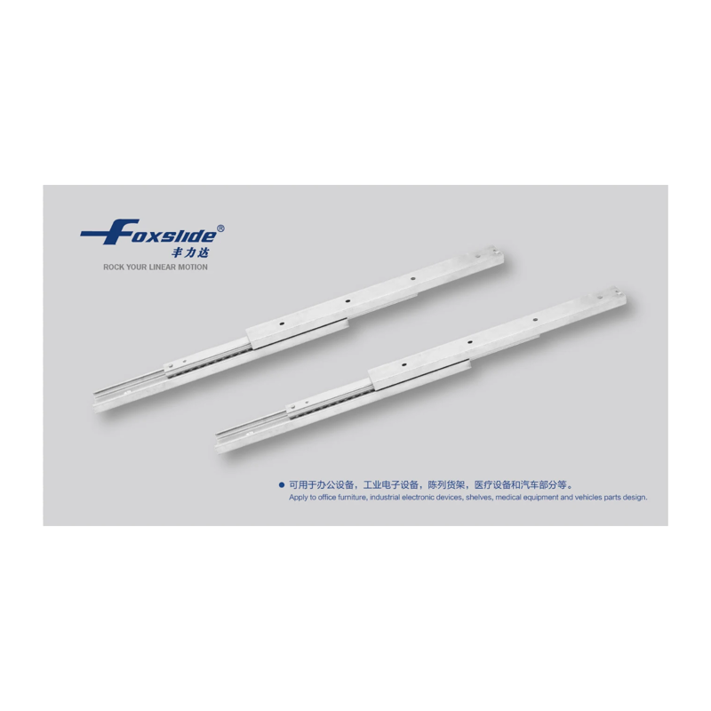
FX3028 series steel extra-heavy-duty telescopic slides feature Gr15 bearing steel balls, a steel body, and a blue-white zinc-plated finish for high rigidity, wear resistance, and corrosion resistance. These non-detachable, side-mounted slides provide partial extension in both directions and are suitable for heavy-duty pull-out applications in office equipment, industrial electronics, display shelving, medical equipment, and automotive components. Slide lengths range from 130~1170 mm in 80 mm increments, with corresponding travel of 74~601 mm and load capacities of 633~7868 N (approximately 65~800 kg). Load capacity increases linearly with length. A and B indicate the numbers of mounting holes in the inner and outer rails, respectively, and also increase with length. The final number in the model designation indicates the slide length in mm, allowing selection based on the available installation space.
FX3036 Series Slide Rails
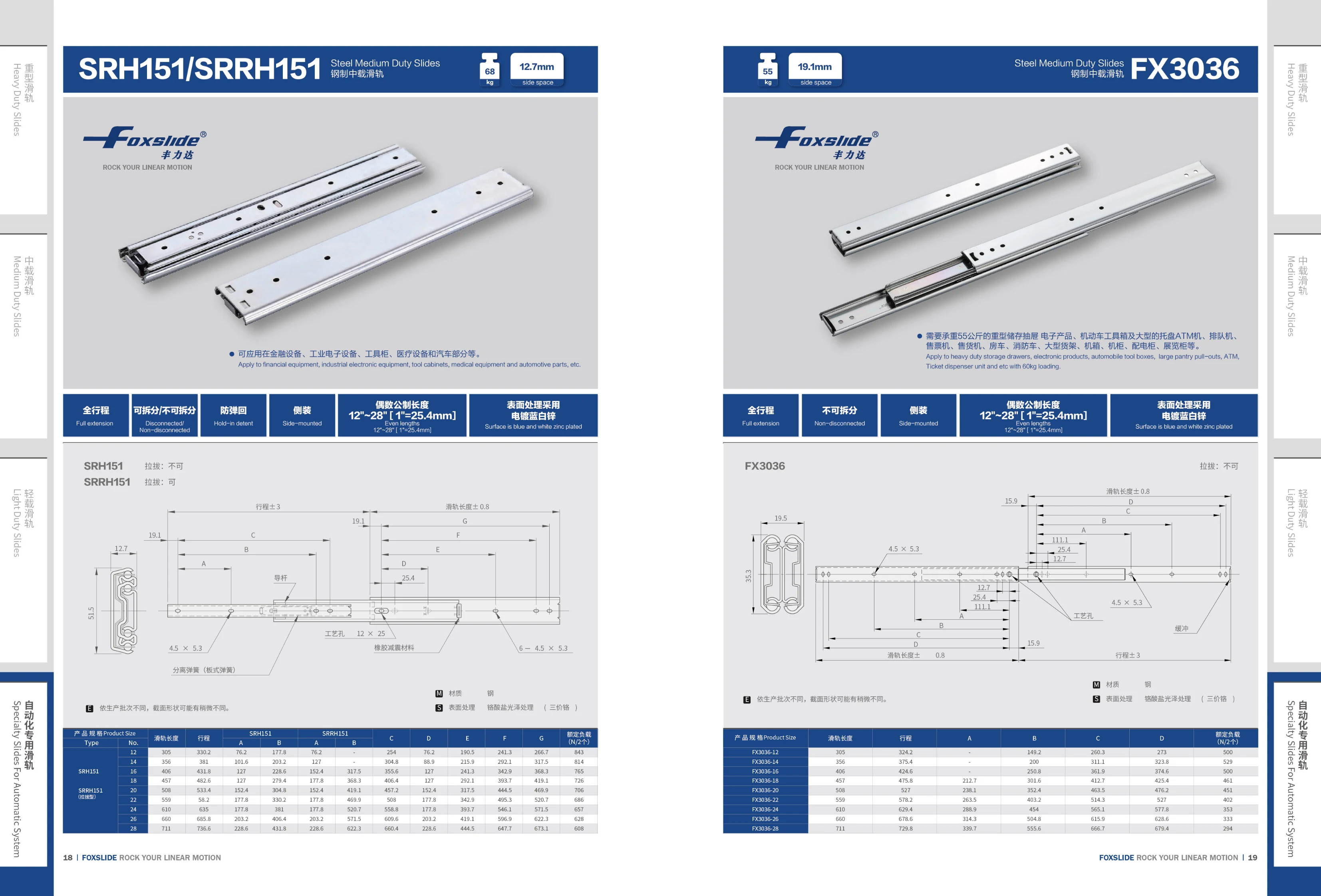
The FX3036 series consists of industrial slide rails (linear slide rails). The catalog lists various rail length and travel combinations under model codes FX3036-12 through FX3036-28, with rail lengths ranging from 305~711 mm and travel from 324.2~729.8 mm. Each model specifies four mounting and overall dimensions, A, B, C and D (in mm), as well as a rated load based on 2 sliders. Rated loads range from 294~529 N and gradually decrease as the model size increases. The rails have a compact design and fixed mounting hole positions, making them suitable for linear guidance applications such as machine tool safety doors, electrical cabinets, automation equipment drawers and short-travel sliding tables. When selecting a model, determine the rail length and travel based on the available installation space, then check the rated load against the application requirements.

FX3036B Stainless Steel Medium-Duty Slide Rail
The FX3036B stainless steel medium-duty slide rail is designed for linear motion applications with medium loads. The page specifies a cross-sectional dimension of 19.1mm and a side clearance of 19.1mm. The catalog lists specifications for the FX3027 series in 7 stroke options: stroke 200~500mm, slide rail length 228.8~524mm, mounting hole spacing A of 140~440mm and B of 160~460mm, and rated load (per 2 sliders) of 275~373N. Load capacity decreases as stroke increases. These slide rails offer corrosion resistance and smooth operation, making them suitable for automation equipment, medical devices, food processing machinery, and other applications requiring high levels of rust resistance.

FX3045 Steel Light-Duty Slide
The FX3045 is a FOXSLIDE steel light-duty drawer slide with a profile width of 12.7mm, a rated load capacity of 45kg, and a maximum size of 950×950. Its blue-white zinc-plated finish provides corrosion resistance and smooth operation. It is designed for light-duty sliding applications in office furniture, cabinets, household drawers, and industrial electronics enclosures. Its mounting holes match those of conventional three-section ball-bearing slides, allowing it to directly replace comparable imported slides. The slide is stamped from cold-rolled steel strip, and its ball-bearing cage operates smoothly and quietly, making it suitable for frequent daily use. Optional front-locking or soft-close mechanisms in the same series are available, with full- or partial-extension configurations for furniture, chassis, and cabinet applications.
FX3051 Series Medium-Duty Slides
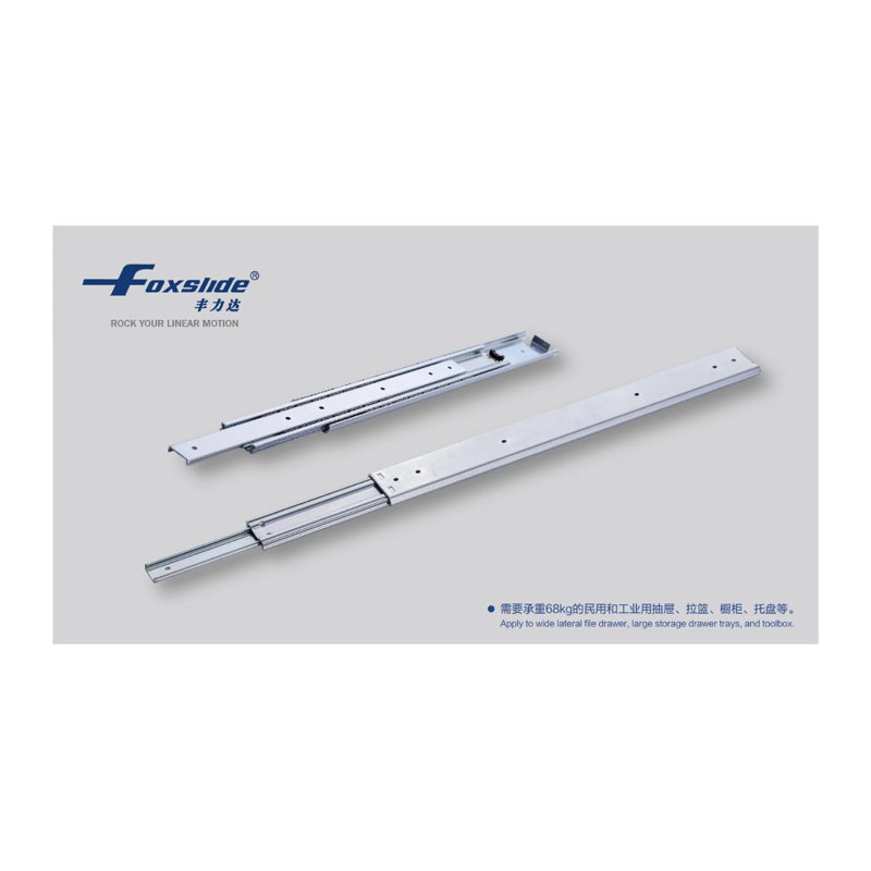
FX3051 series medium-duty slides are linear drawer slides with a blue-white zinc-plated finish for good rust and corrosion resistance. They are suitable for industrial cabinets, tool cabinets, equipment drawers, and other applications requiring moderate load capacity and smooth extension. The catalog lists 16 sizes from 10″ to 40″ in 2″ increments, corresponding to closed lengths L1 of 250–1000 mm (each closed length corresponds to its nominal inch size, e.g., 10″=250 mm and 40″=1000 mm). For each size, the catalog lists the closed length, extension length, and mounting hole positions and related dimensions for A′, B′, C′, A, B, C, D, E, F, and G (in mm), making it easy to select a slide that matches the mounting holes in the cabinet or equipment. When selecting a slide, first determine the closed length (the total length when the slide is retracted) based on the available installation space, then check the mounting hole spacing on the drawer and cabinet and the required extension length.
FX3053B Stainless Steel Heavy-Duty Slide
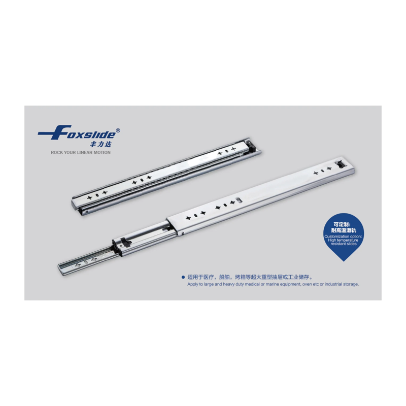
The FX3053B is a stainless steel heavy-duty slide designed for linear motion applications in factory automation equipment that require corrosion resistance and heavy-load guidance, such as mechanisms exposed to moisture, washdown, or mildly corrosive environments. Its stainless steel construction emphasizes load capacity and durability, making it suitable for drawers, safety doors, movable workbenches, and automated linear guide mechanisms. The catalog specifies a side mounting clearance of approximately 19.0 mm; travel, rated load, and mounting hole positions must be confirmed against the complete drawings. When selecting the slide, verify the actual load, available mounting space, and environmental corrosivity, and ensure that the mounting surfaces are flat and the fasteners are suitable.

FX3076 Series Heavy-Duty Slides
FX3076 series heavy-duty slides are suitable for applications requiring full extension, including high-load mobile cabinets, industrial cabinets, containers, multipurpose transport vehicles, automation equipment, and storage equipment. Their heavy-duty construction is available in different lengths to suit cabinet depth. Model suffixes indicate length in inches, with standard sizes from 10 to 58 inches in 2-inch increments, corresponding to overall lengths of 254 mm to 1473.2 mm. The catalog also provides mounting and overall dimensions A–S to assist with cabinet design and hole placement. Applications include financial equipment, industrial electromechanical equipment, tool cabinets, medical equipment, and multipurpose transport vehicles.

FX3076L Series Full-Extension Side-Mount Slides
The FX3076L series consists of heavy-duty, full-extension side-mount drawer slides that allow drawers to be pulled out completely for easy access. Lock-in/lock-out functionality secures the drawer in both closed and extended positions, keeping it safely closed in environments subject to vibration, such as moving vehicles. The non-disconnect design improves installation stability. These side-mount slides are suitable for a range of industrial storage applications, including financial equipment, industrial electronics, tool cabinets, medical equipment, and automotive components. Available in even-inch lengths from 12"~80" (1"=25.4mm), models are designated FX3076L-length to accommodate cabinets of varying depths.
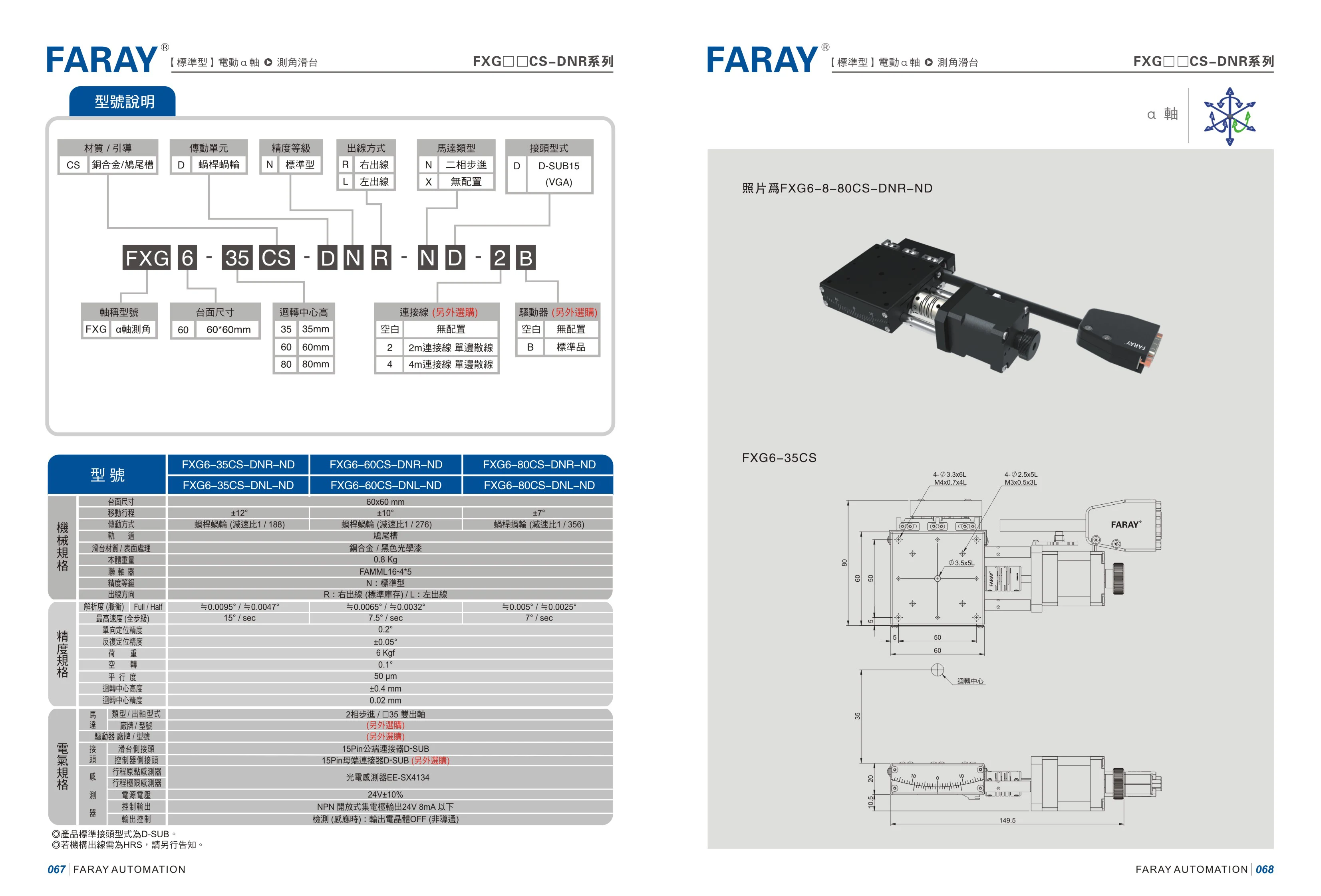
FXG6 Series Linear Modules
The FARAY FXG6 series comprises linear modules available in sizes including 35, 60, and 80. Their modular design accommodates different drive and accessory options, making them suitable for linear transfer, positioning, and other factory automation applications. Model codes specify options such as size, drive type, and accessories, as in FXG6-8-80CS-DNR-ND. Refer to the detailed specification tables in the catalog for parameters such as stroke, lead, and accuracy.