product — Page 87
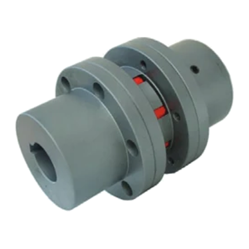
LMS Double-Flange Elastic Jaw Coupling
The LMS double-flange elastic jaw coupling has a simple structure, compact radial dimensions, low weight, and low rotational inertia, making it suitable for medium- and high-speed applications. It provides substantial axial, radial, and angular compensation. Its high-strength polyurethane elastic element is wear- and oil-resistant, offers high load capacity, and provides a long service life with safe, reliable operation. No lubrication is required, maintenance is minimal, and the coupling can run continuously for extended periods. The product range includes multiple sizes, from LMS1 to LMS12, with rated torques from 25 to 12,500 N·m, allowable speeds from 1,500 to 8,500 rpm, and bore diameters from 12 to 160 mm. Custom non-standard versions are available on request, including additional accessories such as keyways.

CF High-Elasticity Rubber Coupling
This high-elasticity rubber coupling offers excellent shock and vibration absorption in a compact, easy-to-install, maintenance-free design with a long service life. It can be installed and removed radially, supports high rotational speeds, and provides effective compensation for axial, radial, and angular misalignment. It can be combined with shaft series products to form a high-elasticity drive shaft. Suitable for industrial power transmission systems, including compressors, pumps, generators, transfer cases, test rigs, locomotive drives, wind turbines, air compressors, and marine propulsion systems. Available in a range of sizes, with bore diameters from 8 mm to 16 mm to suit different torque and installation requirements.
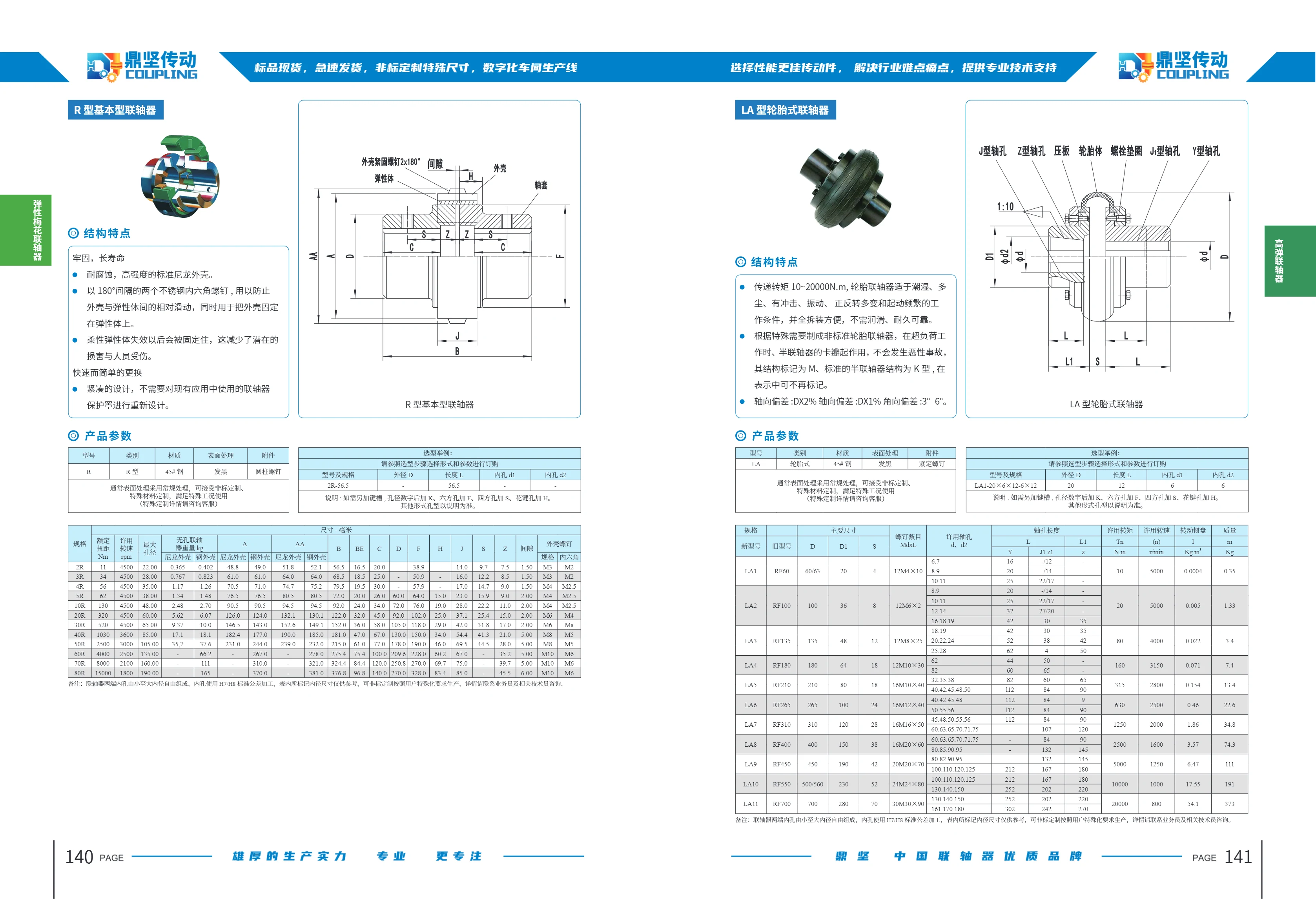
R-Type Standard Coupling
The R-Type Standard Coupling is a robust, long-lasting, corrosion-resistant coupling with a high-strength standard nylon housing. Two stainless steel socket-head screws positioned 180° apart prevent relative movement between the housing and elastomer and secure the housing to the elastomer. If the flexible elastomer fails, it is retained to reduce the risk of damage and personal injury. Its compact design allows quick, easy replacement without redesigning the coupling guard. The coupling is made of 45 steel with a blackened finish and is supplied with cylindrical screws. Available in 13 sizes from 2R to 80R, it has a rated torque range of 11–15,000 Nm, an allowable speed range of 1,800–4,500 rpm, and a maximum bore diameter of 22–190 mm. It is suitable for damp and dusty environments and for operating conditions involving shock, vibration, frequent changes in direction, and frequent starts.

LA Series Tire Couplings
Tire couplings are suitable for operating conditions involving moisture, dust, impact, vibration, frequent changes in rotation direction, and frequent starts. They transmit torque ranging from 10 to 20,000 N·m. Made of No. 5 steel with a blackened finish, they feature a compact design and offer durability and reliability. They compensate for axial and angular misalignment, with axial misalignment of D × 2% and D × 1%, and angular misalignment of 3°–6°. Available models include LA and LA1 through LA20, with various torque ratings and bore sizes.

LB-type tire coupling
The LB-type tire coupling is a highly flexible coupling that provides excellent shock absorption and vibration damping, along with superior compensation for axial displacement. It operates at temperatures from -20 to +80°C and transmits torque from 10 to 20,000 N·m. It is suitable for humid, dusty conditions and applications involving impact, vibration, frequent starting, and frequent changes in direction of rotation. Its one-piece tire-shaped elastic element is durable and reliable, and easy to install, remove, and maintain. Flanges are available with Y, J1, or Z1 bore types. Misalignment compensation: axial, D × 1.5%; radial, D × 1%; angular, 25° to 5°. The bores at either end of the coupling can be configured independently in sizes ranging from small to large. Bores are machined to standard H7/H8 tolerances. Dimensions in the table are for reference only; custom specifications are available.

DLP Polygonal Rubber Coupling
The DLP polygonal rubber coupling is a highly flexible coupling with a simple design. It requires no lubrication and is easy to assemble and disassemble. It provides effective vibration damping and cushioning, and compensates for axial, radial, and angular misalignment. It helps reduce torsional vibration and shock loads in drive shaft systems and prevents resonance. Operating temperature: -30 to 60°C. It is suitable for humid, dusty conditions involving impact and vibration, frequent changes in rotation direction, and frequent starts. Widely used in vibrating screens, light industry, construction machinery, mining machinery, and other industries, it transmits torque from 50 to 8,000 N·m. Made of 45# steel with a blackened surface finish, it comes with set screws. Custom non-standard designs and special materials are available. Models range from DLP1 to DLP71 to suit different torque ratings and installation requirements.

FBS06B Finished-Bore Sprocket
The FBS06B finished-bore sprocket is a standardized sprocket for 06B roller chains. It comes with a finished bore and can be mounted directly on a drive shaft without further machining, making it suitable for low-power drives in conveying, packaging, light industrial machinery, and similar applications. Designed for 06B chain, the series has a chain pitch P of 9.525 mm, chain inner width W of 5.72 mm, roller diameter Dr of 6.35 mm, and tooth width T of 5.3 mm. These dimensions are fully compatible with the internationally used 06B chain (equivalent in size to ANSI 35). The catalog lists dimensions by tooth count, including the corresponding tooth-count code, pitch circle diameter, outside diameter, root diameter, hub outside diameter, overall width, finished bore diameter, and keyway. Select the required sprocket from the table based on tooth count and shaft diameter. Made from medium-carbon or alloy steel blanks, the sprockets are formed by hobbing or shaping and heat-treated at the tooth surfaces. They offer accurate tooth profiles, smooth and quiet operation, and good wear resistance, making them a common alternative to imported standard sprockets in chain drive systems.

FBS25B Series Finished Bore Sprockets
Shenma Transmission FBS25B finished bore sprockets are designed for 04C (25B) single-strand roller chain, with a chain pitch of 6.35 mm, inner chain width of 3.18 mm, roller diameter of 3.3 mm and tooth width of 2.8 mm. Available with 14~63 teeth, they have an outer diameter of 32~130 mm, pitch diameter of 28.54~127 mm, hub diameter of 20~35 mm, overall length of 15 mm and a unit weight of approximately 0.05~0.32 kg. The finished bore is machined to H7 tolerance and includes a keyway and threaded holes for set screws. Bore sizes of 10/12/15/16/18/20 mm are available, with corresponding keyways of 3×1.4, 4×1.8, 5×2.3 and 6×2.8 and threaded holes of M4/M5/M6. Made from high-quality 45 steel, the teeth are induction hardened and tempered. Custom 5U5304 stainless steel versions are available, with black oxide or zinc-plated finishes. Packaging consists of cartons and wooden cases.

FBS60B Finished Bore Sprocket
The FBS60B finished bore sprocket is a Jiama Transmission product designed for 12A roller chain drive systems. Its finished bore allows it to be installed directly. Key catalog specifications include a chain pitch of 19.05 mm, chain inner width of 12.7 mm, roller diameter of 11.91 mm, tooth width of 11.7 mm, and 9 teeth. Designed for standardized chain drives, it is commonly used in conveyors, packaging equipment, agricultural machinery, and general industrial drives. Select the sprocket according to the chain number, tooth count, finished bore size, and available installation space to ensure proper chain engagement. The page's OCR table contains duplicate entries; refer to the specifications corresponding to chain number 12A.

FBS60SD Finished Bore Sprocket
The FBS60SD finished bore sprocket is suitable for 12A (No. 60) roller chain, with a chain pitch of 19.05mm, an inner chain width of 12.7mm, a roller diameter of 11.91mm, and a tooth width of 11.7mm. The bore is finish-machined at the factory for direct installation on a standard shaft, reducing on-site machining. Typically made from 45# steel or medium-carbon steel, the sprocket has induction-hardened teeth for good wear and impact resistance. It is widely used in conveyor, packaging machinery, agricultural machinery, and other drive systems. Refer to the specification table when selecting the number of teeth, bore diameter, and keyway dimensions.
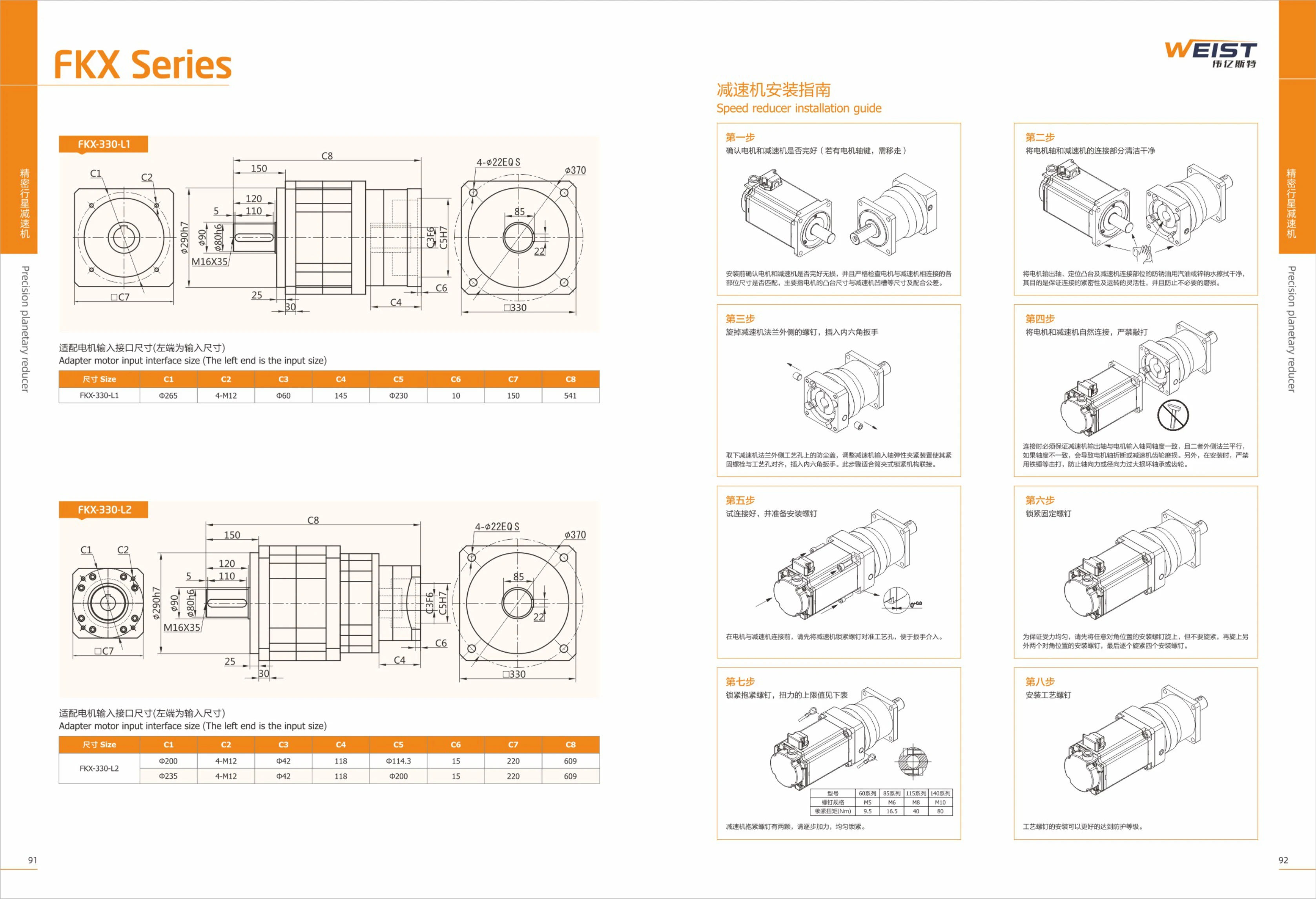
FKX-330-L1 Series Precision Planetary Gearbox
The FKX-330-L1 Series precision planetary gearbox is designed for high-precision drive applications, combining a compact structure with high torque output. It accommodates a range of motor input interface dimensions. The dimensions on the left are for the input side and include two flange sizes (Φ265/Φ235), 4-M12 bolt holes, and a Φ42 locating hole. The installation guide outlines eight steps to ensure the motor and gearbox are connected correctly. Suitable for industrial automation equipment, robots, machine tools, and other applications.
FLBX40 Series
This page provides dimensional drawings for the FLBX40 series, listing three models/configurations: FLBX40-C, FLBX40-L, and FLBX40-R. The catalog does not specify material, travel, accuracy, load capacity, or other parameters. When selecting a model, consult the corresponding dimensional drawing to confirm the mounting interface and overall dimensions. This series is intended for component selection in factory automation equipment. Refer to the complete catalog and drawings for detailed specifications.
FLBX60/FLBY60 Series Manual Translation Stages
The FLBX60/FLBY60 series consists of manual precision translation stages with SUS440C stainless steel bodies, micrometer head drives, and 60mm×60mm platforms. FLBX60 provides movement along the X axis, while FLBY60 provides movement along both X and Y axes. All models have a travel range of ±6.5mm, a load capacity of 196N(20kgf), a minimum scale division of 0.01mm, and a travel parallelism of ≤0.005mm/13mm. The FLBX60-C has a platform thickness of 15mm, a parallelism of 0.02mm, and a weight of 0.4kg; all other models have a platform thickness of 30mm, a parallelism of 0.04mm, and a weight of 0.8kg. Model suffixes include C/L/R. The stages are suitable for optical, inspection, and precision positioning applications.
FLBX60/FLBY60 Series Linear Modules
The FLBX60/FLBY60 series is a range of size 60 linear modules from FARAY AUTOMATION. The catalog page provides dimensional drawings for four basic configurations, distinguished by mounting/structural arrangement and travel: FLBX60-C, FLBY60-C, FLBX60-L, and FLBY60-L. FLBX60 and FLBY60 are two alternative carriage/guide rail arrangements, while C and L denote two length (travel) variants of each arrangement. Select a model based on the load, travel, and available mounting space. Refer to the corresponding dimensional drawing for overall length, carriage mounting hole positions, travel, height, and other dimensions, and check for interference with the host assembly, coupling/motor mount, and cable carrier before ordering. This page contains dimensional drawings only; refer to the series specification page for repeatability, maximum speed, allowable load moments, motor configurations, and other specifications.
FLBX80 Series
The FLBX80 series consists of components for factory automation equipment. This page provides outline dimension drawings. The series includes two types, FLBX80 and FLBY80, each available in -C, -L, and -R variants, for a total of 6 models. This catalog page only shows outline dimensions and corresponding models; it does not list technical specifications such as material, accuracy grade, or rated load. For model selection, consult the dimension and specification tables in the complete catalog.
FLBY80 Series Linear Modules
The FLBY80 series consists of linear module bodies (single-axis slides) for factory automation. The catalog lists two orientation codes, FLBX80 and FLBY80, each available in C, L, and R variants. These typically indicate the mounting position of the motor or drive end (center, left, or right) or differences in structural orientation. This page provides only dimensional drawings for checking the outline, mounting surfaces, and interface locations of each variant. Specific technical parameters such as effective stroke, lead, repeatability, rated load, allowable moment, and maximum speed are not listed; consult the specification tables on other pages for the same series when selecting a model. The known model structure is “FLB + orientation letter (X/Y) + 80 + mounting variant (C/L/R).” For a non-standard stroke or special mounting arrangement, specify the complete model number along with the stroke and accessory sections when ordering.
FLGX40 Series Linear Modules
The FLGX40 series is available in three configurations: C, L and R (FLGX40-C, FLGX40-L and FLGX40-R). The catalog provides outline drawings showing the overall profiles and mounting dimensions of each configuration for use in product selection and equipment design. All three configurations share the same basic specifications but differ in their arrangement (centered, left-facing or right-facing), allowing flexible selection based on motor, cable outlet or mounting surface orientation where installation space is limited. Different configurations can also be used at different stations on the same machine. When selecting a module, refer to the dimensional drawing for the relevant configuration to verify mounting hole locations, overall height and width, and the interface with the driven component. Allow sufficient space for travel and clearance. This page contains dimensional drawings only and does not list performance parameters such as rated load, travel or accuracy grade. Consult the series specification page before making a final selection.
FLGX60 Series Manual Translation Stages
FLGX60 series manual translation stages feature a 60mm×60mm platform, ±6.5mm travel, a minimum scale increment of 0.01mm, and a rated load of 39.2N (4kgf) for precise manual movement and positioning. Two configurations are available: single-axis X (20mm platform thickness, 0.03mm parallelism, 0.21kg weight) and two-axis XY (40mm platform thickness, 0.06mm parallelism, 0.42kg weight). Travel parallelism is ≤0.02mm/13mm. The model suffixes C/L/R indicate different mounting and operating positions, allowing for multi-axis combinations and installation in confined spaces. Applications include optical component adjustment, inspection fixtures, and precision positioning in laboratories.
FLGX60 Series Linear Modules
The FLGX60 series is a size 60 linear motion module/linear slide offered by FARAY AUTOMATION. The catalog provides dimensional drawings for three configurations: FLGX60-C, FLGX60-L and FLGX60-R. C/L/R generally distinguish the mounting orientation or cable outlet/interface position (center, left-facing and right-facing). All three share the same external profile and mounting dimension references. Select the C/L/R variant based on available space and cable routing. The remaining cross-sectional dimensions, effective stroke and mounting hole locations are common to the same size. Refer to the complete catalog specifications and dimensional drawings for the effective stroke, lead, repeatability, rated load and other parameters.
FLS125 Series XYθ Multi-Axis Combination Stages
The FLS125 series consists of FARAY® manual multi-axis combination stages that stack an XY translation stage with a θ-axis rotation stage for precise adjustment along all three axes. The stage has a Φ125mm diameter platform and an aluminum alloy body with a black anodized finish. It is driven by micrometer heads with a minimum scale graduation of 0.01mm. XY travel is ±12.5mm, while the θ axis offers 360° coarse adjustment and ±5° fine adjustment. Load capacity is 49N (5kgf). The series includes the FLS125-LM and FLSP125-LM models, weighing 2.42kg and 2.72kg respectively. They are suitable for aligning samples and fixtures in optical lens, laser path, semiconductor inspection, and precision measurement applications. Select a model based on load capacity (≤5kgf), platform size, and whether θ-axis fine adjustment is required. During setup, lock each axis before adjusting the next to ensure repeatable positioning accuracy.
FLT125-LM-2/FLTP125-LM-2 Three-Axis Translation Stages
The FLT125-LM-2 and FLTP125-LM-2 are manual three-axis (XYZ) translation stages with black-anodized aluminum alloy bodies and micrometer head drives for smooth, repeatable fine adjustment. The stage diameter is Φ125mm, with ±12.5mm of travel along the XY axes and 20mm along the Z axis. The minimum graduation is 0.01mm, and the rated load is 49N (5kgf). In a six-axis configuration, they also provide 360° coarse and ±5° fine rotational adjustment, making them suitable for spatial position and orientation alignment of optical components, sensors, probes, and fixtures. The two models have identical movement directions, materials, drive mechanisms, stage dimensions, travel ranges, and load capacities; only their overall weights differ slightly: 4.40kg for the FLT125-LM-2 and 4.70kg for the FLTP125-LM-2. Choose according to the assembly configuration and load requirements.
FLWFV25 Series Linear Motion Modules
The FLWFV25 series consists of linear motion modules (linear stages) for factory automation. Available in mirror-image L and R configurations, they support symmetrical left-right installation and can be selected to suit the motor shaft, wiring, and operating-face orientation. The catalog lists FLWFV25-L and FLWFV25-R separately, each with its own dimensional drawing for checking table dimensions, mounting hole locations, body profile, and surrounding clearance. The catalog page does not provide detailed specifications such as travel, lead, accuracy grade, or rated load. For product selection, consult the complete dimensional drawings and ordering instructions to determine the effective travel, motor mounting method, limit switches, and accessory configuration.
FLWFV60/FLWFDV60 Series Linear Modules
FLWFV60 and FLWFDV60 are two variants in the same FARAY AUTOMATION series. Each is available in L and R versions based on orientation and mounting configuration, giving four models: FLWFV60-L, FLWFV60-R, FLWFDV60-L, and FLWFDV60-R. The catalog provides dimensional drawings showing the outline and mounting hole locations for each model to assist with selection and installation. The 60 in the model number denotes the 60 frame size (body width class). The series is suitable for linear motion, positioning, and material handling mechanisms in factory automation equipment and can be used with servo or stepper motors and their corresponding drives. The supplied page contains dimensional drawings only; detailed specifications such as stroke, lead, accuracy grade, rated load, and maximum speed are not listed. Refer to the full catalog when selecting a model.
FLWFX60/FLWFV60 Series Linear Modules
The FLWFX60/FLWFV60 series comprises size 60 linear modules (electric linear slides). The series includes two structural types, FLWFX60 and FLWFV60, each available in two symmetrical versions according to mounting and cable exit direction: L (left) and R (right). The four basic models are FLWFX60-L, FLWFX60-R, FLWFV60-L, and FLWFV60-R, enabling symmetrical layouts and mirrored installation on either side of automated equipment. The catalog provides dimensional drawings showing the external and mounting interface dimensions of each model. These can be used to determine mounting hole positions, carriage and slide profiles, and how they fit with other components. When selecting a model, first choose the X or V structure based on load, stroke, and available installation space, then select the L or R direction to suit the equipment layout. These modules are typically used with servo or stepper motors, couplings, and sensors. Actual stroke, lead, positioning repeatability, maximum load, and maximum speed should be checked against the relevant specification page or confirmed with the manufacturer.
FLWX25 Series Dovetail Rack-and-Pinion Driven Linear Stage
The FLWX25 series is a dovetail linear stage with a rack-and-pinion drive, suitable for high-frequency operation, rapid movement, and long-travel applications. Its lightweight aluminum alloy body makes it easy to integrate into other equipment. Multiple sliders can be configured for long-travel linear motion. The table measures 25×42 mm. Models are distinguished by lengths from L50 to L200, with travel from 30 to 180 mm, a load capacity of 29.4 N (3 kgf), parallelism of 0.05 to 0.15 mm, and weight of 0.12 to 0.25 kg.
FLWZ25 Series Rack-and-Pinion Linear Stages
The FARAY FLWZ25 series consists of rack-and-pinion-driven linear stages with lightweight aluminum alloy bodies, suitable for integration into other equipment. The rack-and-pinion drive enables high operating frequencies, making the stages suitable for applications requiring fast movement and long travel. Multiple sliders can be configured for long-travel applications. The catalog lists four models: FLWZ25-L50, L70, L100, and L150. All have a table size of 25 × 42 mm. Their lengths L are 50/70/100/150 mm, with corresponding travel distances of 30/50/80/130 mm and weights of 0.13/0.14/0.17/0.22 kg.
FLX/FLY70 Series Manual Translation Stages
The FLX/FLY70 series consists of manual translation stages with 70mm×70mm platforms, black anodized aluminum alloy bodies, and micrometer head drives. They are suitable for optical, inspection, and precision positioning applications. FLX70 provides single-axis X movement, while FLY70 provides two-axis XY movement. Travel is ±6.5mm (±12.5mm available on request), with a minimum graduation of 0.01mm, a load capacity of 65N (6.6kgf), and travel parallelism of ≤0.01mm/13mm. The FLX70-C has a platform thickness of 18mm, parallelism of 0.03mm, and a weight of 0.30kg. All other models have a platform thickness of 36mm, parallelism of 0.05mm, and a weight of 0.60kg. The C/L/R model suffixes indicate different configurations.
FLX/FLY90 Series Manual Translation Stages
The FLX/FLY90 series consists of manual translation stages with 90mm platforms, black anodized aluminum alloy bodies, and micrometer head drives. They are suitable for optical, inspection, and precision adjustment applications. The FLX90 provides single-axis movement along the X axis and has a platform thickness of 18mm; the FLY90 provides two-axis movement along the XY axes and has a platform thickness of 36mm. The platform measures 90mm×90mm, with a travel range of ±12.5mm (±6.5mm available as a custom option), a minimum scale graduation of 0.01mm, travel parallelism of ≤0.02mm/25mm, and a load capacity of 93.1N (9.5kgf). The FLX90-C has a parallelism of 0.03mm and weighs 0.47kg; the FLX90-L/R and all FLY90 models have a parallelism of 0.06mm and weigh 0.94kg. The model suffixes C/L/R indicate the micrometer head mounting position (center/left/right), allowing selection according to the available operating space.
FLX100 Series Manual Translation Stages
The FLX100 series comprises manual translation stages in two configurations: the single-axis X-direction FLX100 and the two-axis XY-direction FLY100, each available in C, L, and R variants. They feature a black anodized aluminum alloy body and micrometer head drive, with a 100mm×100mm platform, ±12.5mm travel, 98N (10kgf) load capacity, and 0.01mm minimum scale division. The FLX100 has a platform thickness of 20mm, weighs 0.68kg, and has a parallelism of 0.03mm; the FLY100 has a platform thickness of 40mm, weighs 1.36kg, and has a parallelism of 0.06mm. Travel parallelism is ≤0.02mm/25mm. These stages are suitable for fine positioning in optics, precision measurement, and laboratory applications.
FLX100 Series Linear Modules
The FLX100 series is a range of linear motion modules (linear slides) from FARAY AUTOMATION. Page 69 of the catalog provides dimensional drawings for three configurations: FLX100-C, FLX100-L, and FLX100-R. All three share the same FLX100 base cross-section and mounting interfaces but differ in drive-end arrangement and mounting orientation, allowing a choice of left-side, right-side, or center shaft placement in confined spaces. Select the specific model based on stroke, lead, load, and mounting orientation. The dimensional drawings can be used to verify the body length, slider mounting hole positions, and interface dimensions. This page provides dimensional information only. For detailed specifications such as rated load, maximum speed, repeatability, and motor configuration, see the other pages for this series.
FLX120 Series Manual Translation Stages
The FLX120 series consists of manual single-axis (X-axis) precision translation stages with black anodized aluminum alloy bodies. The 120mm×120mm platform is 30mm thick, providing a compact, rigid structure. Driven by a micrometer head, each stage offers ±25mm of travel and a minimum graduation of 0.01mm for micrometer-level fine feeding and position adjustment. Motion parallelism of ≤0.05mm/50mm and parallelism of 0.05mm ensure straight travel and platform stability. With a rated load of 196N (20kgf) and a weight of approximately 1.52kg, these stages are suitable for positioning and adjusting small to medium loads such as optical components, sensors, fixtures, and probes. The series includes FLX120-C, FLX120-L, and FLX120-R models with different configurations and mounting orientations, offering the same platform size and travel to suit different installation and operating directions. They are commonly used for manual fine adjustment in optical experiments, inspection equipment, and automated production lines.
FLX120 Series Linear Modules
The FLX120 series consists of size 120 linear modules (linear stages). The catalog page provides dimensional drawings for three configurations—FLX120-C, FLX120-L, and FLX120-R—distinguished by their mounting and drive arrangements. Each has a different body orientation and cable outlet/drive position, allowing designers to select the configuration that suits the equipment layout. The series uses 120 as its cross-sectional size designation. Selection is based primarily on dimensions shown in the drawings, including body width, mounting hole locations, stroke, and slider platform dimensions. This page contains dimensional drawings only and does not specify technical values such as stroke, lead, accuracy grade, allowable load, or speed. Confirm the selection using the stroke and specification tables in the complete catalog. During installation, note the differences in body orientation among the C/L/R configurations to avoid interference with surrounding mechanisms.
FLX125 Series Linear Modules
The FLX125 series comprises size 125 linear motion modules (linear stages) in the FARAY AUTOMATION catalog. Dimensional drawings show the mounting envelope and interface dimensions for three structural variants: FLX125-C, FLX125-L, and FLX125-R. These drawings support model selection, installation space planning, and interface verification during equipment design. The three variants use the same size 125 main body with different structural and mounting configurations, typically a standard configuration and left- and right-hand mirror-image configurations. They accommodate different installation orientations for linear handling, positioning, and pressing in automated equipment. Refer to the dimensional drawings on this page to determine mounting hole locations, overall dimensions, and interface dimensions. Travel, lead, accuracy grade, drive method, and motor configuration are not listed on this catalog page and must be confirmed with the manufacturer.
FLX160/FLY160 Series Linear Modules
The FLX160/FLY160 series linear modules have a frame size of 160 and are available in two designs: FLX and FLY. The catalog identifies each configuration by its main model and mounting orientation: FLX160 is available in L (left) and R (right) cable exit/mounting orientations, while FLY160 has corresponding LM and RM variants. The supplied page contains dimensional drawings for the series, showing the outlines, mounting hole locations, and interface dimensions for all four configurations: FLX160-L, FLX160-R, FLY160-LM, and FLY160-RM. These drawings help equipment designers verify installation clearances and design base plates or adapter plates. The modules provide reciprocating linear motion in automated equipment, carrying a slider to position tooling, fixtures, material handling devices, dispensing mechanisms, and other equipment along a linear path. They are suitable for 3C assembly, lithium battery, photovoltaic, packaging, and general custom automation lines. Selection should take into account travel, load, speed, mounting orientation (L/R/LM/RM), and module mounting dimensions. For specific travel and performance parameters, refer to the specification tables in the complete catalog.
FLX30/FLY30 Series Manual Translation Stages
The FLX30/FLY30 series consists of micrometer-driven manual translation stages with a 30mm×30mm platform. Their aluminum alloy bodies have a black anodized finish and offer a compact, lightweight, and rigid design. The series is divided into two types by direction of travel: FLX30 provides single-axis X travel, with a platform thickness of 15mm, a weight of 0.06kg, and parallelism of 0.02mm; FLY30 provides two-axis XY travel, with a platform thickness of 30mm, a weight of 0.12kg, and parallelism of 0.04mm. Each type is available in C, L, and R configurations, distinguished by micrometer head position. All models have a travel range of ±3mm, a micrometer head minimum graduation of 0.01mm, a rated load of 14.7N (approximately 1.5kgf), and travel parallelism of ≤0.005mm/6mm. They are suitable for short-travel precision positioning and fine adjustment of optical components, sensors, probes, optical fibers, and similar devices. They can be used individually or combined into multi-axis adjustment assemblies.
FLX30/FLY30 Series
The FLX30/FLY30 series comprises mechanical body models presented in the catalog as dimensional outline drawings. The series has three configurations, -C, -L, and -R, distinguished by mounting and cable exit direction, covering six models: FLX30-C, FLY30-C, FLX30-L, FLY30-L, FLX30-R, and FLY30-R. FLX and FLY are parallel subseries with a cross-section size of 30; the C/L/R suffixes indicate different orientations or mounting configurations. When selecting a model, consider the available installation space and cable exit direction, and check the mounting hole locations and overall dimensions against the outline drawings. This page provides dimensional illustrations only; for technical specifications such as stroke, load, and accuracy, refer to the specification tables on the other pages for this series.
FLX30 Series Manual Translation Stages
FLX30 series manual translation stages feature a black-anodized aluminum alloy body and a micrometer drive. They have a 30mm×30mm platform, a ±3mm travel range, a 14.7N(1.5kgf) load capacity, and a 0.01mm minimum scale graduation. The series includes FLX30-C/L/R models with single-axis X movement and FLY30-C/L/R models with two-axis XY movement. Platform thicknesses are 15mm (FLX30-C) and 30mm, respectively. Travel parallelism is ≤0.005mm/6mm, parallelism is 0.02mm or 0.04mm, and weight is 0.06kg or 0.12kg. These stages are suitable for optical, inspection, and small-scale precision positioning adjustments.
FLX40/FLY40 Series Manual Translation Stages
The FLX40/FLY40 series consists of micrometer-driven manual translation stages with a 40mm×40mm platform. Their compact, lightweight aluminum alloy bodies have a black anodized finish and are suited to precise positioning and fine adjustment of optical components, miniature fixtures, and samples. The series includes FLX40 models with X-axis movement and FLY40 models with XY-axis movement. Each type is available in C, L, and R variants according to the drive/mounting position. All models have a travel range of ±6.5mm, a micrometer head with a minimum graduation of 0.01mm, a load capacity of 29.4N (3kgf), and motion parallelism of ≤0.01mm/13mm. The FLX40-C has a platform thickness of 18mm, parallelism of 0.02mm, and a weight of 0.14kg; all other models have a platform thickness of 36mm, parallelism of 0.04mm, and a weight of 0.28kg. Different mounting orientations support single-axis fine adjustment or combined multi-axis positioning.
FLX40 Series Linear Modules
The FLX40 series comprises linear modules (linear stages) for factory automation. This catalog page provides dimensional drawings for the series, covering two body configurations: FLX40 and FLY40. Three variant codes, C, L, and R, identify six models: FLX40-C, FLX40-L, FLX40-R, FLY40-C, FLY40-L, and FLY40-R. The 40 in the model number is the size designation. Select the FLX or FLY configuration and the C/L/R variant based on the cross-sectional dimensions and body profile, together with the required travel, load capacity, mounting space, and motor mounting orientation. Then use the dimensional drawings on this page to check the body length, mounting hole locations, and surrounding clearance to ensure proper fit with the machine frame and connecting components. For travel, accuracy, rated load, and other specifications, refer to the subsequent specification pages for this series.
FLX50 Series Manual Translation Stages
The FLX50 series consists of compact manual translation stages driven by micrometer heads. They feature a 50mm×50mm platform and a black-anodized aluminum alloy body for a compact, rigid construction. There are two configurations: FLX50 provides linear motion along the X axis with a platform thickness of 18mm, while FLY50 provides motion along both the X and Y axes with a platform thickness of 36mm. Both are available in C, L, and R models, which differ in micrometer head mounting position. All models have a travel range of ±6.5mm, a minimum scale division of 0.01mm, a load capacity of 44N (approximately 4.5kgf), and a motion parallelism of ≤0.01mm/13mm. Parallelism is 0.02mm for single-axis models and 0.04mm for dual-axis models, with respective weights of 0.18kg and 0.36kg. They are suitable for precision positioning and fine adjustment of optical components, sensors, probes, fixtures, and similar equipment. They can be used individually or combined with other translation stages to create multi-degree-of-freedom positioning systems.
FLX50 Series Linear Modules
The FLX50 series comprises linear modules (linear slides) for factory automation equipment. Page 51 of the catalog provides outline dimensional drawings showing the overall and key mounting dimensions of the FLX50 and FLY50 subseries. The models shown are divided into C, L, and R variants according to their mounting or output shaft configuration: FLX50-C, FLX50-L, FLX50-R, FLY50-C, FLY50-L, and FLY50-R. These correspond to different motor and drive orientations, allowing selection based on space constraints and mounting direction. The 50 in the model name indicates the nominal series size, with a slide/profile width of approximately 50 mm. When selecting a model, check the mounting hole positions, travel range, and interface dimensions against the corresponding outline drawing. The supplied page contains only outline dimensional drawings; it does not specify travel, accuracy, load, speed, or other parameters, nor does it provide the complete model coding rules. For detailed specifications, refer to the other pages for this series or contact the manufacturer.
FLX60/FLY60 Series Manual Translation Stages
The FLX60/FLY60 series manual translation stages feature a black anodized aluminum alloy body, micrometer head drive, and a 60mm×60mm platform. FLX60-C/L/R models provide single-axis movement along the X axis, while FLY60-C/L/R models provide movement along both the X and Y axes. The FLX60-C has a platform thickness of 18mm, parallelism of 0.03mm, and weight of 0.24kg; all other models have a platform thickness of 36mm, parallelism of 0.06mm, and weight of 0.48kg. Travel is ±6.5mm, with ±12.5mm available as a custom option. Load capacity is 49N(5kgf), minimum scale division is 0.01mm, and travel parallelism is ≤0.01mm/13mm. These stages are suitable for manual fine adjustment in optics, inspection, precision positioning, and similar applications.
FLX60 Series Linear Modules
The FLX60 series consists of size 60 linear modules. This catalog page provides dimensional drawings and lists three configuration codes: FLX60-C, FLX60-L, and FLX60-R. The C, L, and R suffixes typically distinguish motor mounting positions or cable exit directions. Select a configuration based on the available installation space and direction of travel. This page does not provide performance parameters such as stroke, lead, accuracy, load capacity, or speed. Confirm specific dimensions using the corresponding dimensional drawings and technical documentation. The FLY60-C/L/R drawings shown on the same page represent a separate group and are not included in this series' SKUs.
FLX70 Series Linear Modules
The FLX70 series is a range of size 70 linear modules from FARAY AUTOMATION. The catalog provides dimensional drawings for three configurations: FLX70-C, FLX70-L and FLX70-R. These correspond to different body configurations and motor mounting orientations: C is the standard/compact configuration, L has a left-side shaft output or left-facing mount, and R has a right-side shaft output or right-facing mount. When selecting a model, confirm the body configuration code, effective travel, lead, motor mounting method, and whether accessories such as a protective cover are required. Refer to the dimensional drawing for the relevant model for overall length, width and height, mounting hole locations, slider platform dimensions and travel range. The series is commonly used for linear positioning and transfer in automated equipment for electronics assembly, inspection, dispensing and material handling.
FLX80 Series Linear Motion Components
The FLX80 series comprises linear motion components used in factory automation equipment. This catalog page presents dimensional drawings for six configurations or mounting variants: FLX80-C, FLX80-L, FLX80-R, FLY80-C, FLY80-L, and FLY80-R. The C/L/R suffixes distinguish different structures or mounting orientations within each series. Dimensions, stroke, load, accuracy, and materials should be verified against the corresponding dimensional drawings and subsequent specification pages. These components are suitable for automated mechanisms requiring linear guidance, positioning, or reciprocating motion.
FLX90 Series Linear Modules
The FLX90 series consists of size 90 linear motion modules. This page is a model index for their dimensional drawings. The catalog distinguishes three configurations by motor mount and output shaft orientation: C (center), L (left), and R (right). The related FLY90-C/L/R models are shown alongside them on the same drawing for easy comparison of mounting dimensions and overall profiles during selection. The series is suitable for linear transfer, positioning, and pressing mechanisms in automated equipment used in electronics, semiconductors, packaging, lithium batteries, and other industries. This page provides only the model index and drawing numbers; it does not list parameters such as specific stroke, lead, accuracy grade, rated load, or maximum speed. Selection must be confirmed against the stroke sections and mounting hole locations on the corresponding dimensional drawing page. For the complete ordering code, including stroke, protection, and motor configuration, refer to the ordering code guide on the series selection page.
FLXSC160 Series Long-Travel Coarse Adjustment Stages
The FLXSC160 series long-travel coarse adjustment stages are FARAY manual positioning stages designed for applications requiring long travel but infrequent adjustment. The X axis uses precision linear bearings, ground guide shafts, and a ball screw with a 5mm pitch; the vertically moving Z axis uses precision linear bearings and a T-shaped lead screw with a 4mm pitch. Both are driven by handwheels. The stage measures 160mm×160mm and is made primarily of black anodized aluminum alloy. The X axis is available with ±50mm, ±100mm, or ±200mm travel, a load capacity of 98N(10kgf), parallelism of 0.2~0.3mm, straightness of 0.02~0.05mm, and a weight of 5.1~6.8kg. The Z axis is available with ±50mm or ±100mm travel, a load capacity of 7.84N(8kgf), straightness of 0.02~0.03mm, and a weight of 5.8~6.3kg. Travel and stage mounting holes can be customized to customer requirements.
FLY100 Series Manual Translation Stages
The FLY100 series and FLX100 series manual translation stages shown on the same page feature a black anodized aluminum alloy body, a 100mm×100mm platform, and a micrometer head drive. They have a minimum graduation of 0.01mm, a travel range of ±12.5mm, and travel parallelism of ≤0.02mm/25mm. They are divided into two types by direction of travel: FLX100 provides single-axis X movement (platform thickness 20mm, parallelism 0.03mm, load capacity 98N(10kgf), weight 0.68kg); FLY100 provides two-axis XY movement (platform thickness 40mm, parallelism 0.06mm, load capacity 98N(10kgf), weight 1.36kg). Low-profile and K-suffix XY variants are also available: FLY100-CB/LB/RB have a platform thickness of 22mm, load capacity of 39.5N(4kgf), and weight of 0.96kg; FLY100-CBK/LBK/RBK have a platform thickness of 30mm, load capacity of 63.7N(6.5kgf), and weight of 0.88kg. The model suffixes C/L/R correspond to the micrometer head mounting positions (center/left/