Linear Motion Accessories — Page 13

SFE Series Nuts
The SFE series comprises ball screw nut units with nominal diameters from 16 mm to 50 mm and leads from 16 mm to 50 mm. They use balls ranging from 2.778 mm to 7.938 mm and are available with 3 or 6 ball circuits. Featuring high rigidity and load capacity, they are suitable for precision transmission applications.
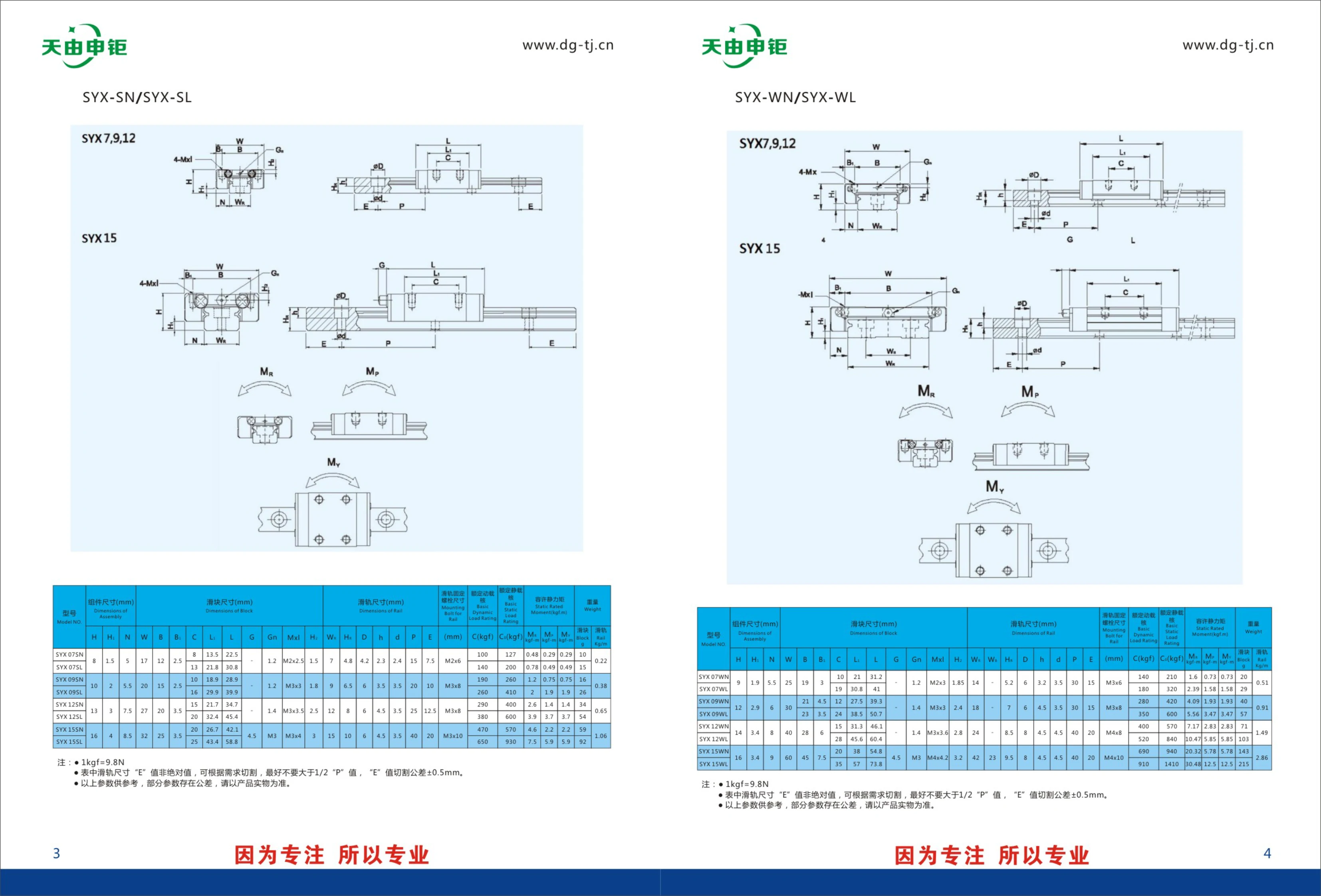
SYX-SL Series Linear Guide Rails
The SYX-SL series comprises linear guide rail and slider assemblies for factory automation. It includes the SYX-SN and SYX-SL subseries, with a range of models such as SYX7, SYX9, SYX12, and SYX15. Designed for precision linear guidance in automated equipment, the series offers slider assemblies in various sizes and load capacities. For specific details, including assembly and slider dimensions, please refer to the product catalog.
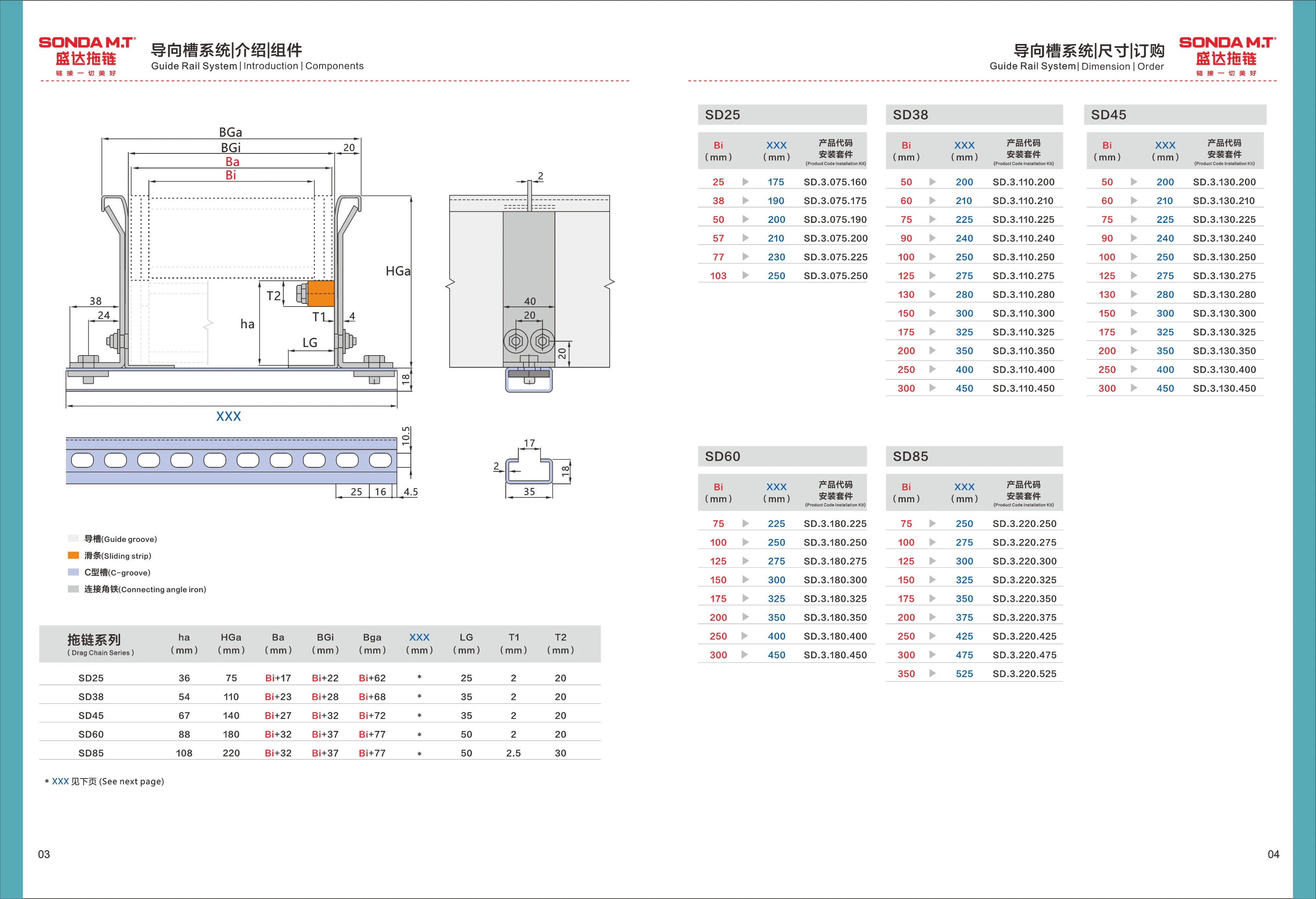
SD Series Linear Guide Mounting Kit
SD Series linear guide mounting kits are designed for SD25, SD38, and SD45 linear guides. A range of Bi and XXX size combinations is available to meet different installation requirements. Product codes follow the format SD.3.xxx.xxx: SD indicates the series, 3 indicates the type, and the following numbers correspond to the XXX and Bi dimensions, respectively. The mounting kit ensures proper installation and alignment of the guide rail and carriage, improving system rigidity and precision.
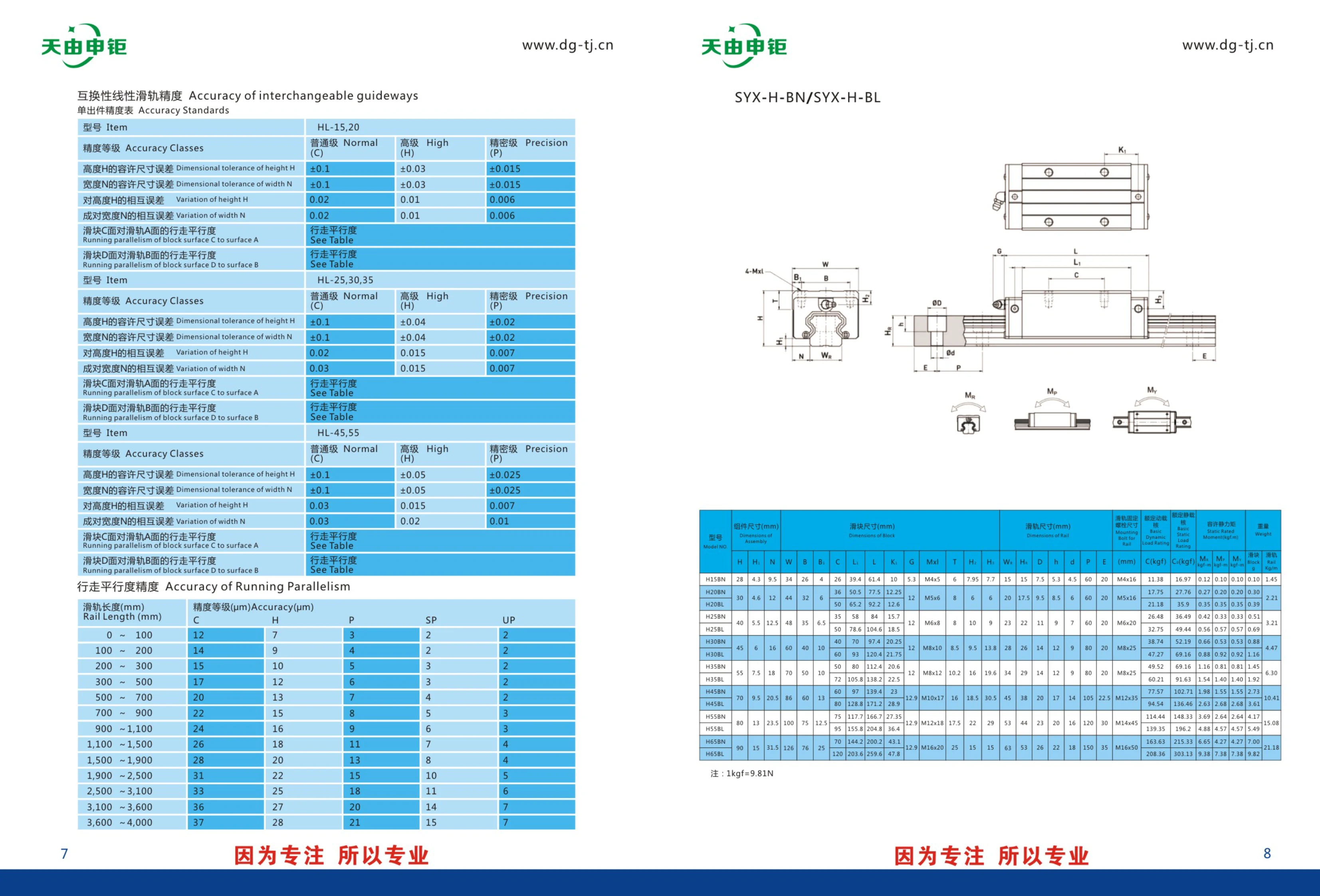
HL Series Linear Guideways
HL series linear guideways are available in three accuracy grades: Normal (C), High (H), and Precision (P). Sizes include HL-15, HL-20, HL-25, HL-30, HL-35, HL-45, and HL-55. Height and width tolerances vary by accuracy grade, making them suitable for guiding linear motion in automation equipment.
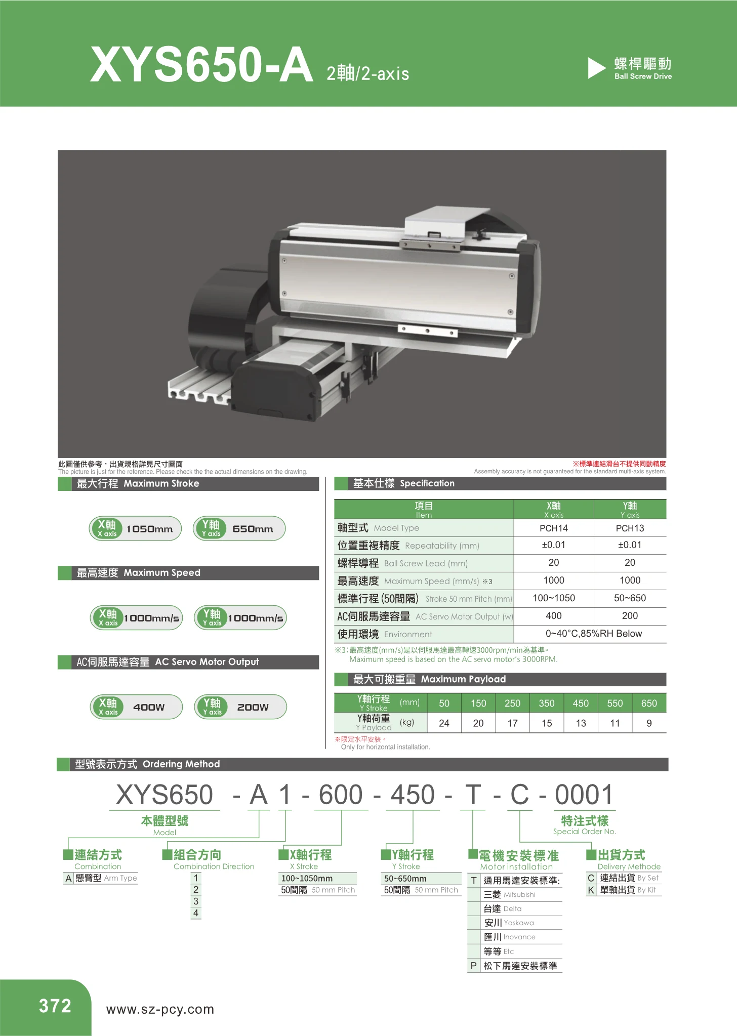
PCH Series Two-Axis Linear Modules
The PCH series consists of two-axis (X-Y) linear modules with a cross-slide structure, combining an X axis and a Y axis. Driven by ball screws and AC servo motors, they are suitable for two-dimensional positioning, material handling, dispensing, and inspection in automated equipment. The X-axis model is PCH14 and the Y-axis model is PCH13. Both axes have a positioning repeatability of ±0.01 mm, a ball screw lead of 20 mm, and a maximum speed of 1000 mm/s. Stroke lengths are available in 50 mm increments: the standard stroke range is 100~1050 mm for the X axis (PCH14) and 50~650 mm for the Y axis (PCH13). The corresponding AC servo motor ratings are 400 W for the X axis and 200 W for the Y axis. Operating conditions are 0~40 °C and below 85%RH. Users can select strokes in 50 mm increments within each axis's range and freely combine X and Y axes to create two-axis modules in different configurations.

YKK Series Single-Axis Robots
YKK series single-axis robots feature a modular design that integrates a ball screw and linear guide rail. They offer high precision, quick installation, compact size, light weight, space savings, and high rigidity. The U-shaped rail is optimized through finite element analysis, and the carriage and rail use a two-row Gothic arch profile with a 45° contact angle to support equal loads in four directions. The range includes YKK40, YKK50, YKK60, YKK86, YKK100, and YKK130 models, with cross-sectional widths of 40~130 mm and heights of 20~65 mm. They are suitable for automated equipment requiring precise linear motion and compact installation.

YKK Series Single-Axis Robots
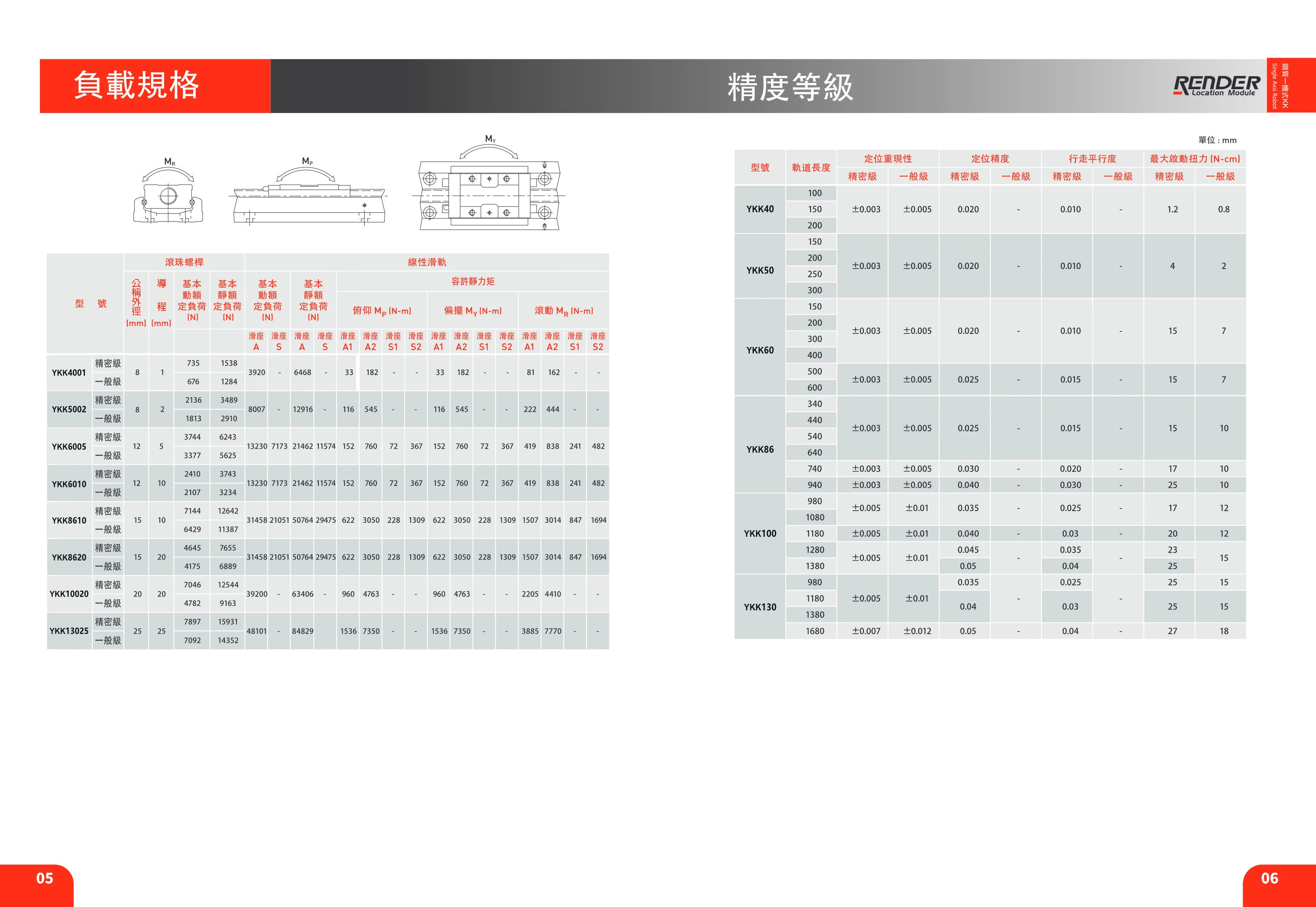
YKK series single-axis robots (linear modules) use ball screw drives and are available in six cross-section sizes: 40, 50, 60, 86, 100 and 130. They support various leads, precision or standard accuracy grades, and a range of rail lengths. Optional aluminum covers, telescopic protective covers, motor mounting flanges and limit switches provide protection against dust and debris, expand motor interface options, and enable carriage positioning, homing and overtravel protection. Special machining, designated E, is available for the ball screw and rail. Grease is recommended for lubrication, with speed limited to 60 m/min. Replenish grease through the carriage grease fitting at the specified intervals; fitting specifications vary by model. Selection should take into account size, lead, accuracy, rail length and motor flange compatibility.
YKK Series Linear Modules
The YKK series consists of semi-enclosed ball screw linear modules that integrate an aluminum extrusion base, precision ball screw, linear guide, coupling, and sensor mounting slots. They are designed for precision linear transfer, positioning, and pushing operations in automated equipment. Standard models include six cross-sectional sizes: YKK40, YKK50, YKK60, YKK86, YKK100, and YKK130. Track lengths are available in increments from 100mm to 1680mm. Maximum stroke varies by model and track length (for example, the YKK40-100 has a maximum stroke of 35mm, while the YKK100-1380 has a maximum stroke of 1346mm). Positioning repeatability is ±0.003~±0.007mm, positioning accuracy is ±0.005~±0.012mm, and travel parallelism is 0.020~0.05mm; accuracy decreases slightly as track length increases. The body includes mounting slots for limit switches and can be fitted with sensors such as the Omron EE-SX671 and PANASONIC GX-F12A / GX-F12A-P for home and limit detection at both ends of travel.
SYX-H-BN Series Linear Guide Rails
The SYX-H-BN/SYX-H-BL series linear guide rails include models HL-15, HL-20, HL-25, HL-30, HL-35, HL-45, and HL-55. Available in three accuracy grades—Normal (C), High (H), and Precision (P)—they have specified dimensional tolerances and matching tolerances for different heights (H) and widths (N). Suitable for automation equipment, machine tools, and other applications requiring high-precision linear motion.
SYX-H-BL Series Linear Guide Rails
The SYX-H-BL series consists of linear guide rail and block assemblies designed to guide linear motion in automation equipment. The series is available in a range of accuracy grades and sizes, and offers high rigidity and load capacity. Made from high-quality steel and precision-machined, these assemblies ensure smooth movement and accurate positioning. The close fit between the block and rail meets the demands of high-speed, heavy-load applications.
LBV Series Crossed Roller Guideway Sets
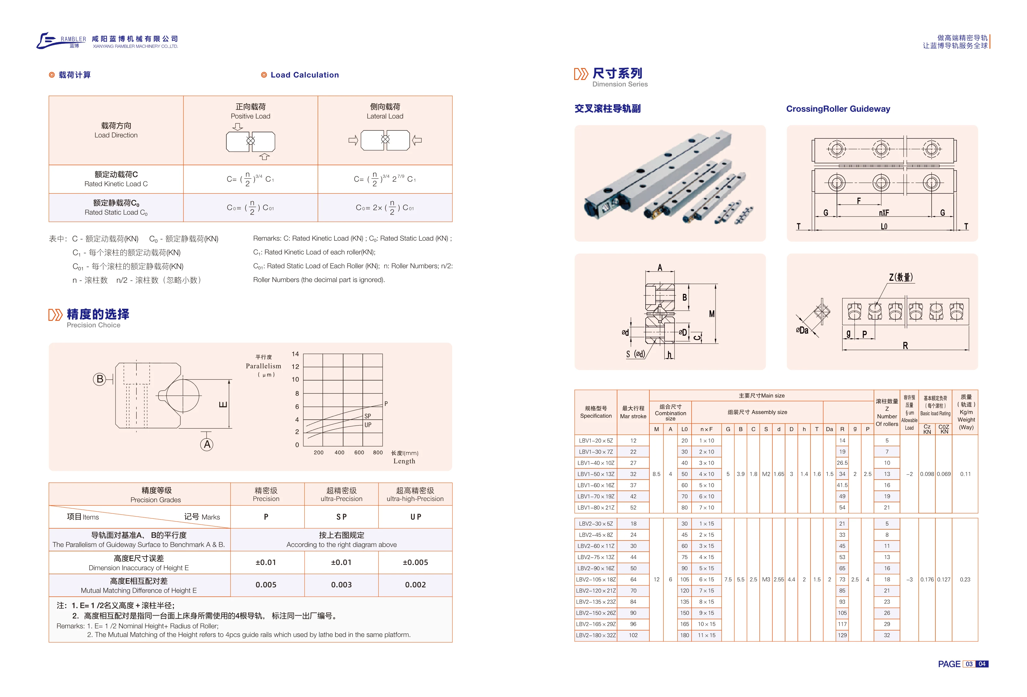
The LBV series crossed roller guideway is a linear guidance component that uses cylindrical rollers arranged at 90° to one another. It can support both vertical and lateral loads simultaneously and offers high rigidity, low friction, and high positioning accuracy. It is suitable for automated equipment requiring high-rigidity, high-precision linear motion. The series comprises two cross-sectional sizes: LBV1 (assembled width 10mm, main dimension 5mm) and LBV2 (assembled width 15mm, main dimension 5mm). Each size is available in multiple assembled lengths (20~80mm for LBV1 and 30~180mm for LBV2), with a corresponding number of rollers (5Z~32Z) and maximum strokes of 12~102mm. Select a model based on parameters including maximum stroke, assembled dimensions, roller count, allowable load, and basic load rating.
LBV Series Roller Linear Guides
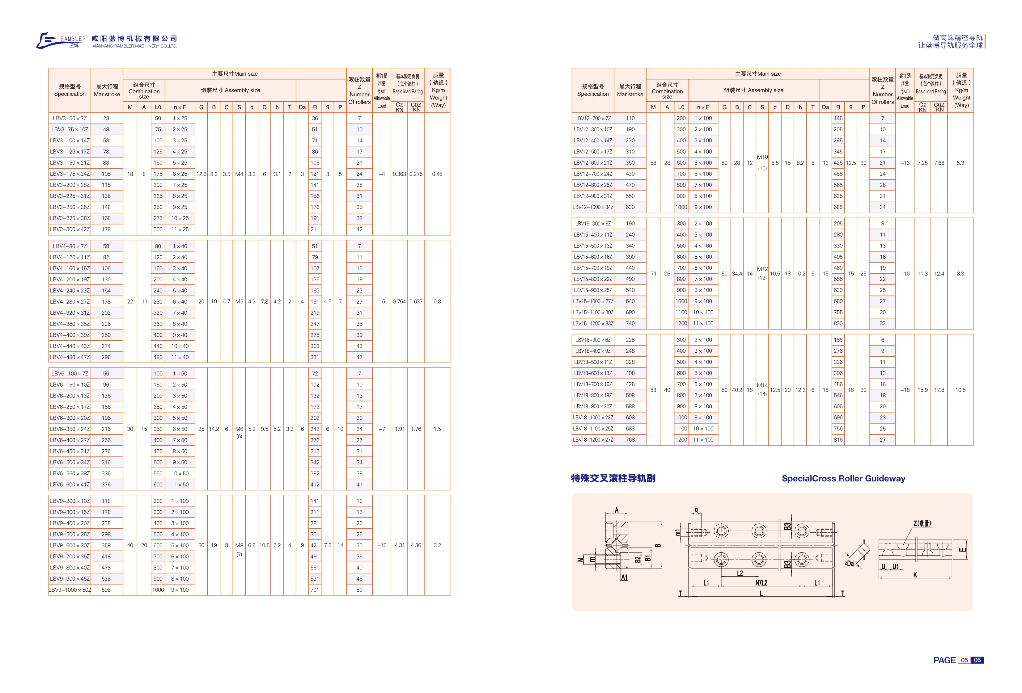
LBV series linear guides use cylindrical rollers as rolling elements. Compared with ball-type guides, the rollers make line contact with the raceways, providing a larger contact area and therefore greater rigidity, higher load capacity, and better impact resistance. They are suitable for heavy-duty cutting, machine tool feed axes, heavy-load handling, and automation equipment. The catalog lists three cross-sectional size codes: 12, 15, and 18. Rail lengths range from 200~1000 mm for size 12 and 300~1200 mm for sizes 15 and 18, in 100 mm increments. Standard mounting holes are arranged at an n×100 pitch, with the number of holes increasing from 1 to 11 as the rail length increases. The catalog specifies the maximum travel for each length: 110~630 mm for size 12, 190~740 mm for size 15, and 228~768 mm for size 18. The model designation follows the format “LBV size-rail length×suffix code.” Suffix codes are specified for each size and length combination; for example, size 12 with a 200 mm rail corresponds to 72, and a 300 mm rail corresponds to 102. When selecting a model, it is necessary to
LBVT Series Roller Linear Guides
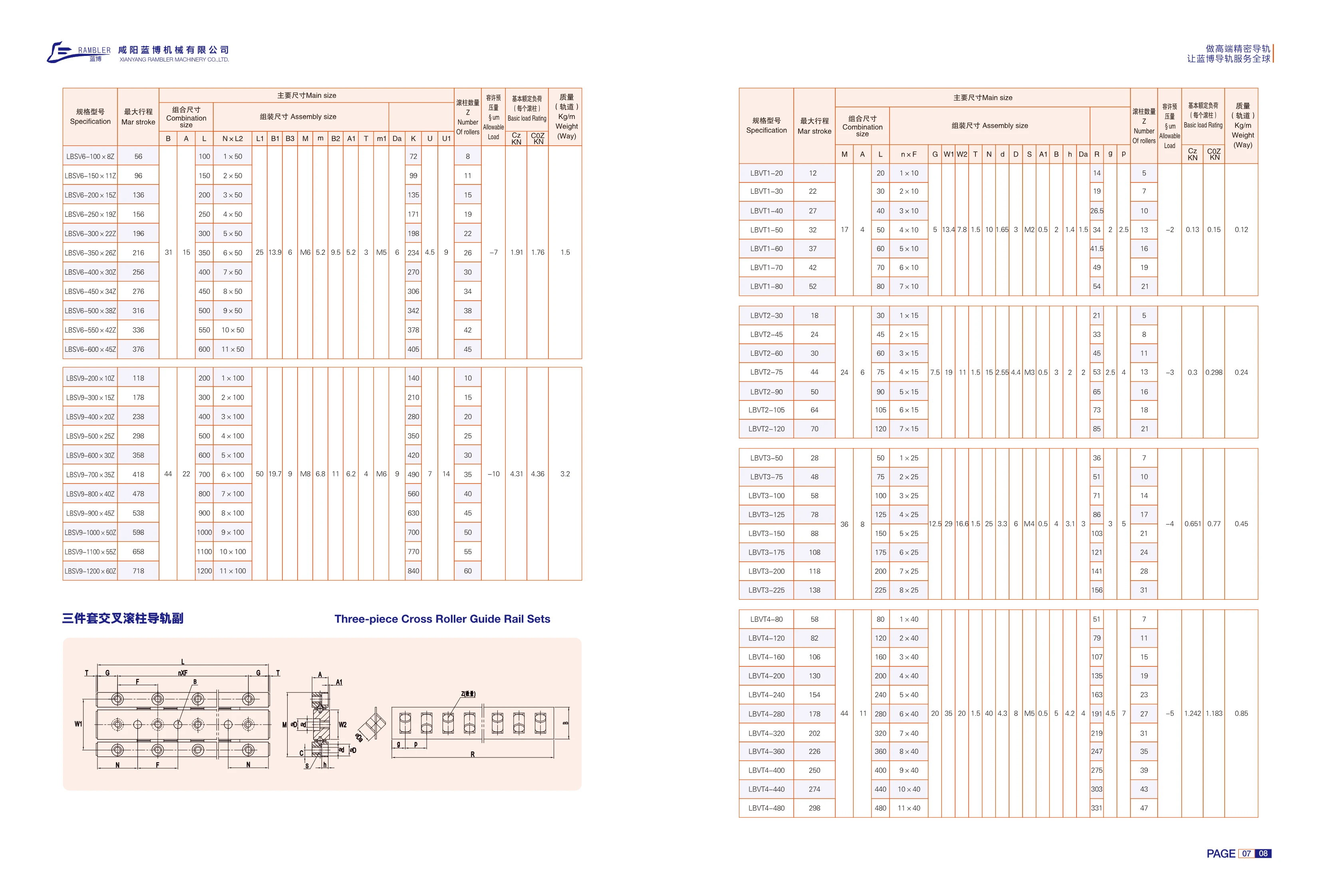
LBVT series roller linear guides use cylindrical rollers as rolling elements. Compared with ball-type linear guides of the same size, they offer a larger contact area, higher load ratings and rigidity, and better resistance to shock and vibration. They are suited to linear motion applications requiring high rigidity and repeat positioning accuracy, such as machine tools, precision measuring instruments, and automated assembly lines. The series comes in four cross-sectional sizes: 1, 2, 3, and 4. Standard rail lengths range from 20~480mm, with corresponding maximum strokes of 12~298mm. Within each size, rail lengths increase in increments of the fixed hole pitch (10mm for size 1, 15mm for size 2, 25mm for size 3, and 40mm for size 4), with the number of mounting holes increasing from 1 to 11. Models are designated LBVT[size]-[rail length] and can be selected based on stroke requirements. Slider preload grades and lubrication accessories can also be specified as needed.
LBSV Series Roller Linear Guides
The LBSV series consists of roller linear guides that use cylindrical rollers as rolling elements. They offer high rigidity, high load capacity, and low friction, making them suitable for heavy-duty linear guidance in machine tools, automated equipment, and similar applications. The LBSV6-100×82 model listed in the catalog has a maximum stroke of 56 mm. Its main dimensions include B=31 mm, A=15 mm, L=100 mm, L1=25 mm, B1=13.9 mm, and B3=6 mm. See the corresponding table for the number of rollers and rated load values.
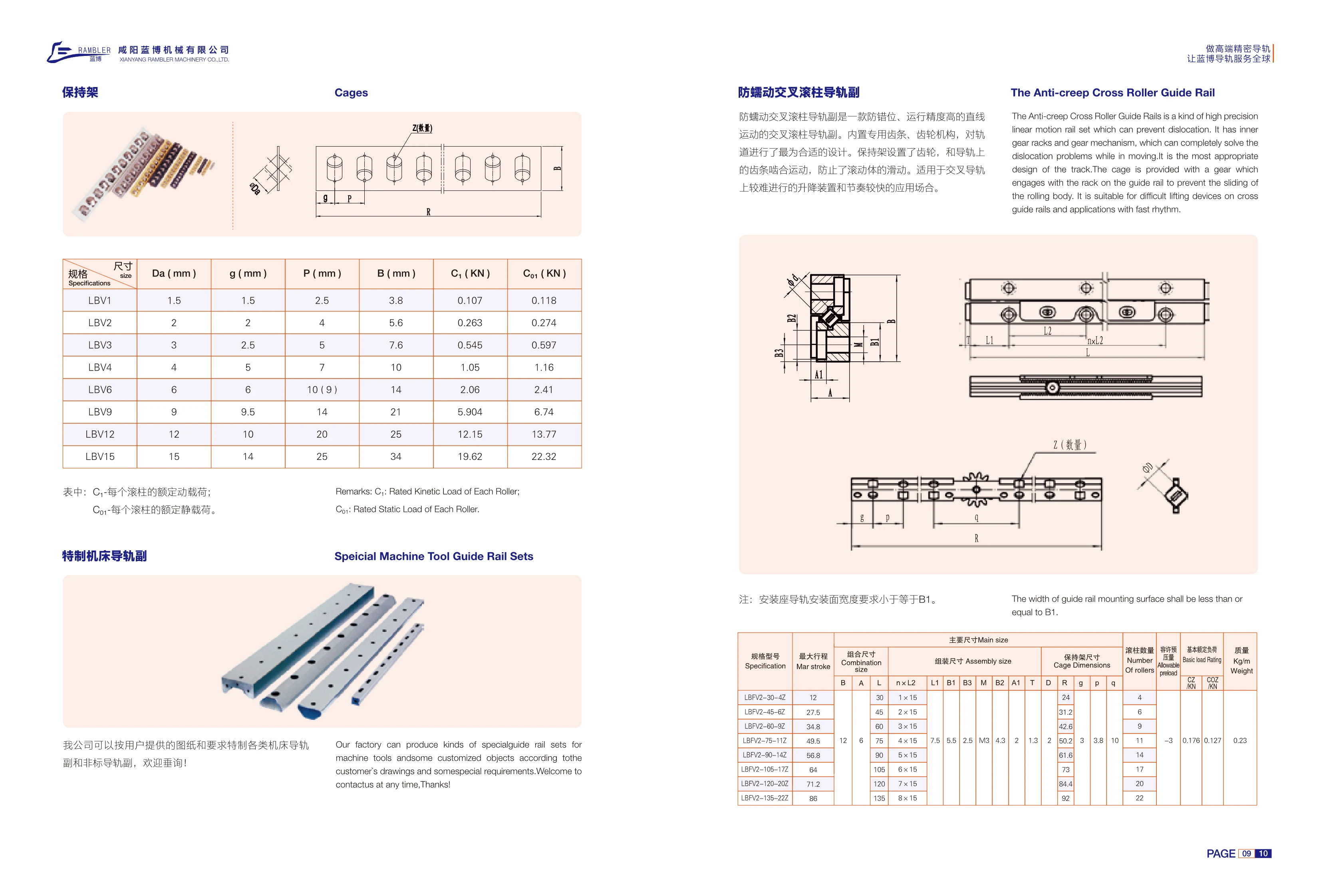
LBV Series Anti-Creep Crossed Roller Guide Set
The LBV series anti-creep crossed roller guide set provides precise linear motion while preventing misalignment. Its built-in rack-and-pinion mechanism features a gear on the cage that engages with a rack on the guide rail. This completely prevents rolling element slip (creep), addressing the challenge of preventing misalignment in lifting devices and high-cycle applications. The width of the guide rail mounting surface on the mounting base must be no greater than B1. The series includes 8 sizes, from LBV1 to LBV15, covering roller diameters Da of 1.5~15mm and guide rail widths B of 3.8~34mm. Basic dynamic load ratings C1 range from 0.107kN to 19.62kN, and static load ratings C01 range from 0.118kN to 22.32kN. These guide sets are suitable for high-precision linear guidance and rapid lifting applications where misalignment must be prevented.
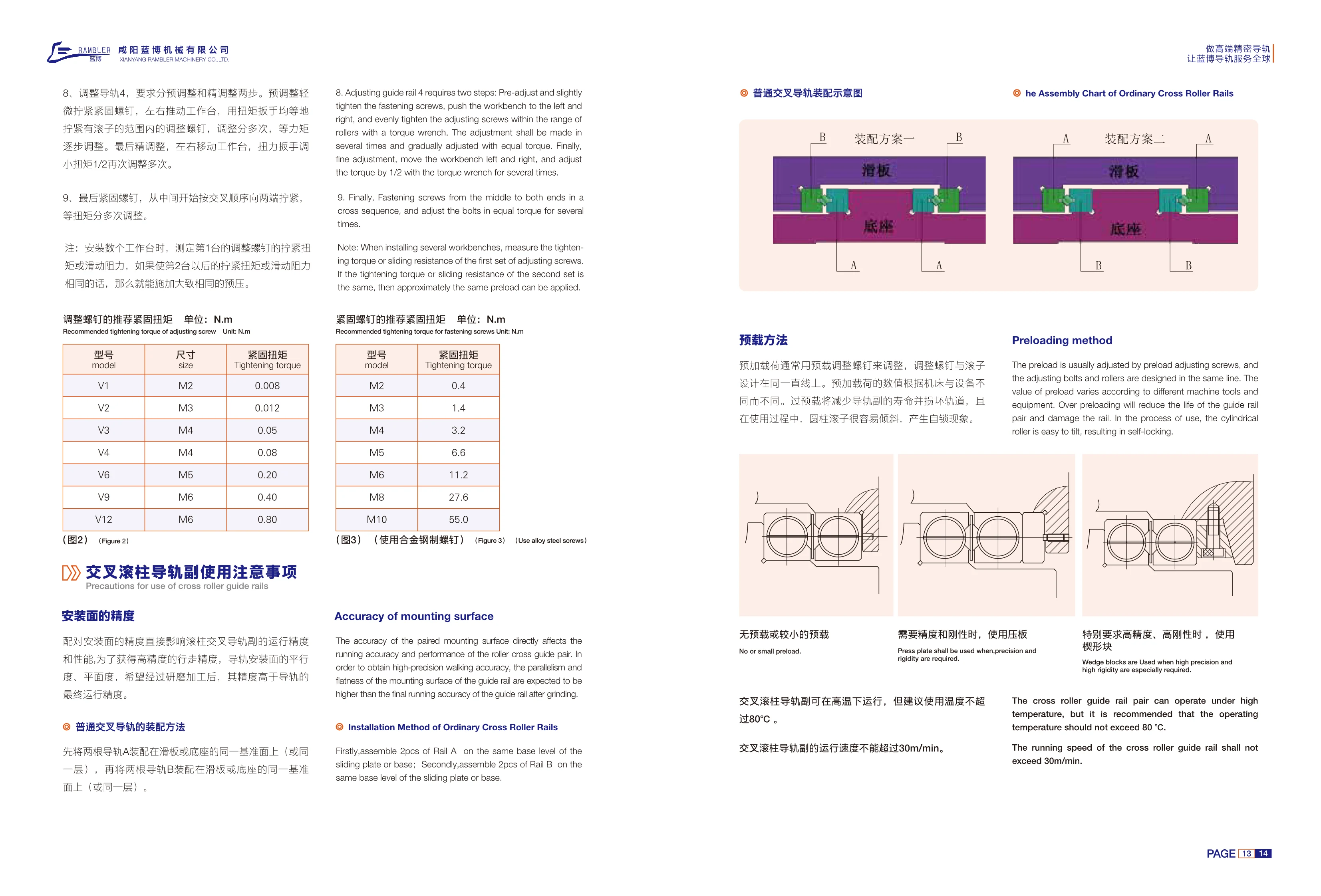
V Series Crossed Roller Guideways
V Series crossed roller guideways are high-precision linear motion guide components. They use cylindrical rollers arranged in a crossed pattern to support loads from multiple directions, making them suitable for machine tools, precision measuring equipment, and automation systems. During installation, the mating mounting surfaces must have flatness and parallelism tolerances tighter than the guideway's final running accuracy; grinding is usually required. Preload is adjusted using preload adjustment screws aligned with the rollers. Adjustment must be performed in two stages, preliminary and fine, with repeated tightening in a crisscross sequence at equal torque. Excessive preload can shorten guideway life, damage the tracks, and cause cylindrical rollers to tilt and lock. The catalog lists adjustment screw sizes and recommended tightening torques for V1, V2, V3, V4, V6, V9, and V12 models, ranging from M2~M6 and 0.008~0.80 N·m, respectively, for reference when setting preload during installation.

M/V Type Needle Roller Guideway Set
The M/V type needle roller guideway set uses a needle roller cage and is suitable for high-load, high-rigidity linear guidance applications. Compared with similar needle roller systems, the LB type composite needle roller cage reduces motion resistance while maintaining high rigidity. The catalog lists six sizes: 3015, 4020, 5025, 6035, 7040, and 8050, with width A of 30~80 mm, height B of 15~50 mm, and needle roller diameter Dw of 2~3.5 mm. Standard lengths can be selected from the length table for each size, with maximum lengths of 1200~1500 mm. Other dimensions are available on request.
N/O and M/V Needle Roller Guideway Sets
N/O and M/V needle roller guideway sets are precision crossed needle roller guideways designed with needle roller cages for high-load applications. The M/V type uses an LB composite needle roller cage that provides low motion resistance and high rigidity compared with similar needle roller systems. The N/O type also uses a needle roller cage, with closely spaced rollers that give the guideway high rigidity. M/V sizes include 3015, 4020, 5025, 6035, 7040 and 8050, with cross-sectional dimensions A=30~80 mm and B=15~50 mm, needle roller diameter Dw=2~3.5 mm, and selectable lengths of 100~1500 mm. N/O dimensions are not listed on this page; please contact us for details.
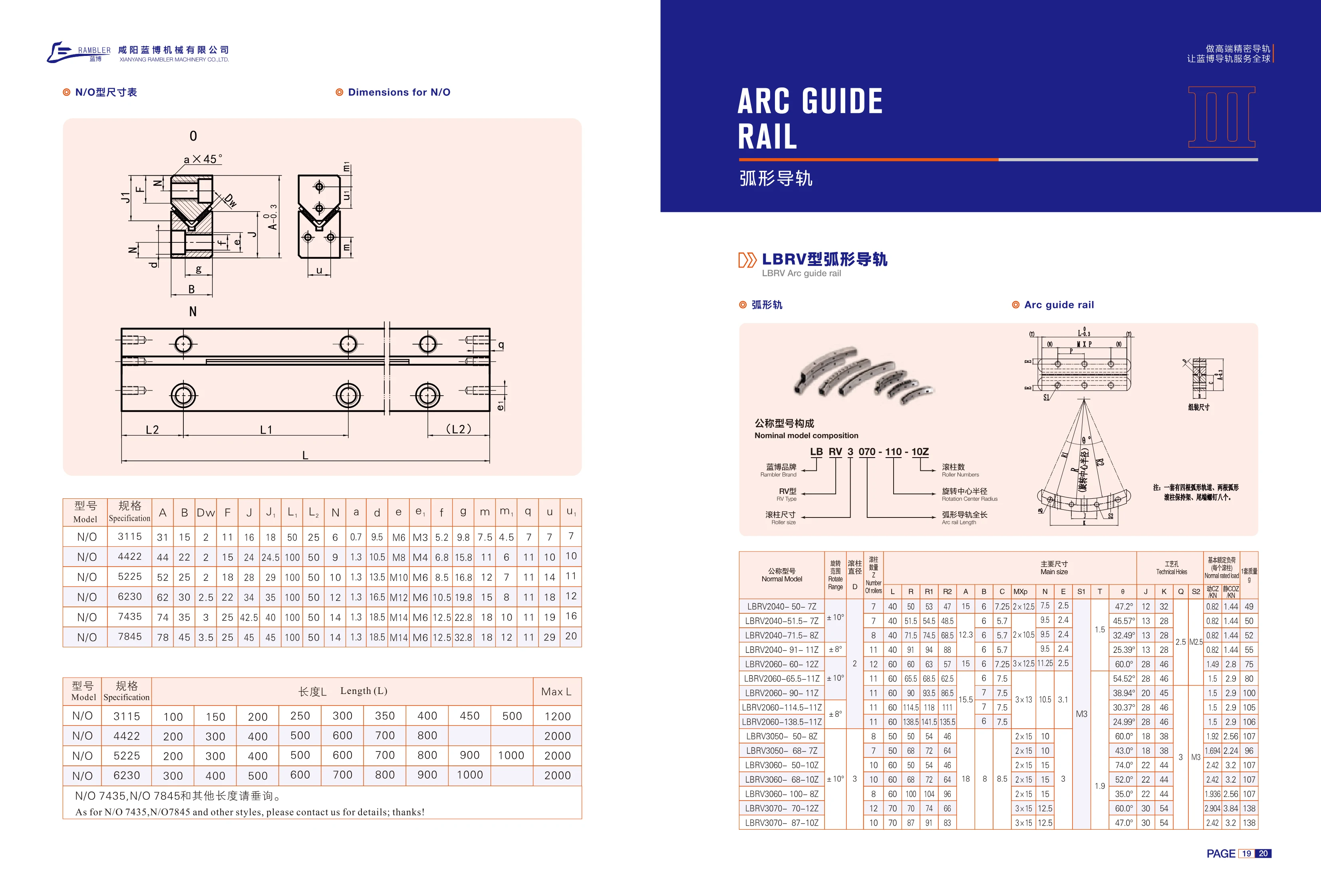
N/O Type Linear Guide Rails
The N/O type linear guide rail (rolling guide rail) series uses model numbers consisting of N/O and a four-digit size code, such as N/O 3115 and N/O 4422. The size code corresponds to the cross-sectional dimensions. The dimension table provides cross-sectional and mounting parameters including A, B, Dw, F, J, J1, L1, L2, N, a, d, e/e1, f, g, m/m1, q and u/u1, where Dw is the ball diameter and e/e1 specifies the threaded holes. Standard lengths vary by size: 3115 is 100~500mm (in 50mm increments, maximum 1200mm); 4422 is 200~800mm (in 100mm increments, maximum 2000mm); 5225 is 200~1000mm (maximum 2000mm); and 6230, 7435 and 7845 are 300~1000mm (maximum 2000mm). Please inquire about 7435, 7845 and other lengths.
LBRV Curved Guide Rail
LBRV curved guide rails provide guidance along an arc and are commonly used in curved workstations, rotary mechanisms, and curved conveying systems in automated equipment. The catalog lists the N/O series in sizes 3115–7845, with cross-sectional widths A of 31–78 mm, heights B of 15–45 mm, roller diameters Dw of 2–3.5 mm, and mounting threads from M6 to M14. Length L can be selected from standard increments, typically 100–1000 mm, with maximum lengths of 1200–2000 mm. Consult us for 7435, 7845, and other lengths.
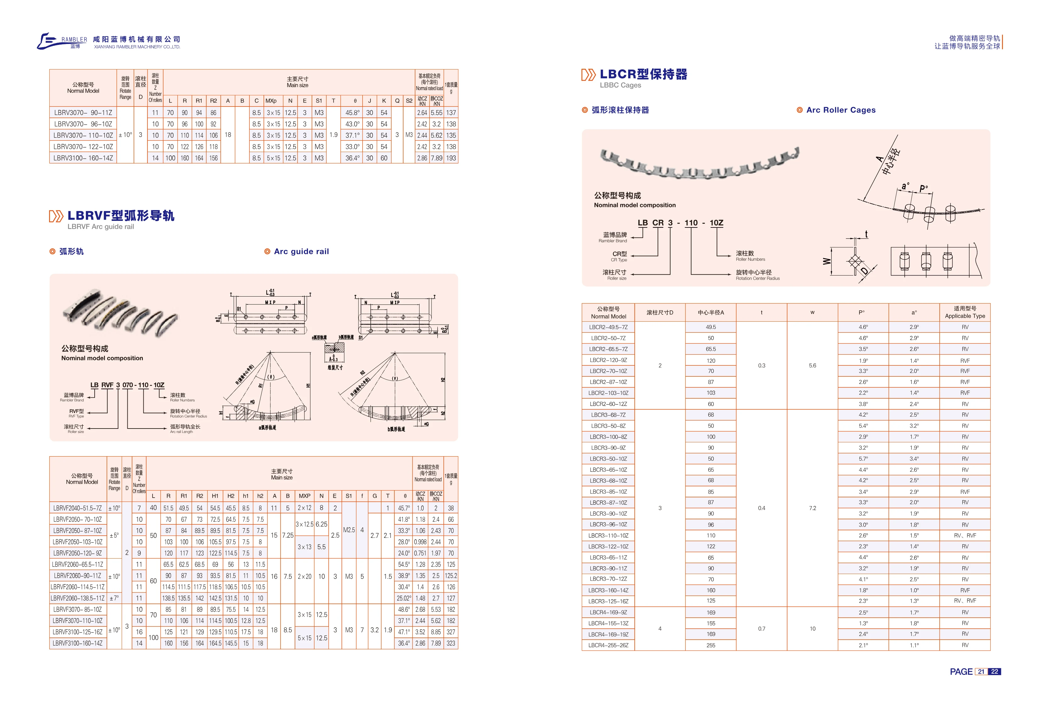
RV Series Curved Guide Rails
RV series curved guide rails provide guidance along an arc and are commonly used with LBCR series roller cages. The series comes in three roller diameters: 2, 3 and 4 mm. Center radii range from 49.5 to 255 mm, and the cages contain 7 to 26 rollers. The P and a angular parameters are used to match the cages to RV and RVF guide rails. The multi-roller cage design offers low friction, high rigidity, accurate positioning and smooth motion. Applications include rotary tables, curved conveyors, inspection equipment and curved slide tables in automated machinery. Select the appropriate LBCR nominal model based on the guide rail model, center radius and roller size.
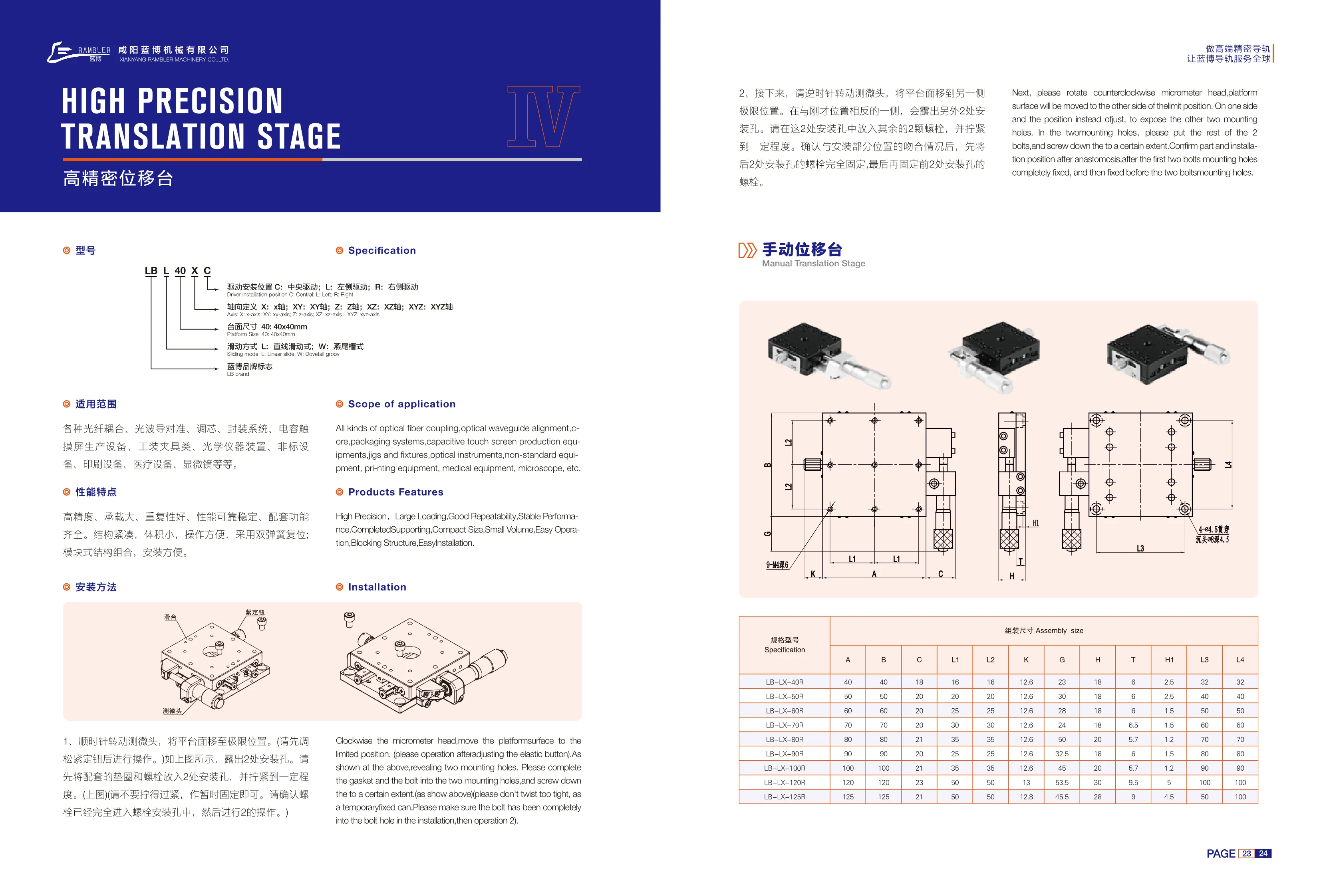
LB-LX Series High-Precision Manual Translation Stages
LB-LX series high-precision manual translation stages use linear sliding guides and are available with platform sizes from 40×40mm to 125×125mm. They support single-axis X, Y or Z motion and combined two-axis XZ or YZ motion. The drive can be mounted in the center (C), on the left (L), or on the right (R). Driven by a micrometer head and equipped with a dual-spring return, these stages offer high precision, high load capacity, good repeatability, reliable and stable performance, a compact size, and easy operation. Their modular construction makes installation easy and offers a full range of compatible functions. Applications include fiber-optic coupling, optical waveguide alignment, core alignment, packaging systems, capacitive touchscreen production equipment, jigs and fixtures, optical instruments, custom equipment, printing equipment, medical equipment, and microscopes. Select the model according to platform size and drive position, and refer to assembly dimensions A/B/C, L1~L4, and K/G/H/T/H1 when planning the installation.
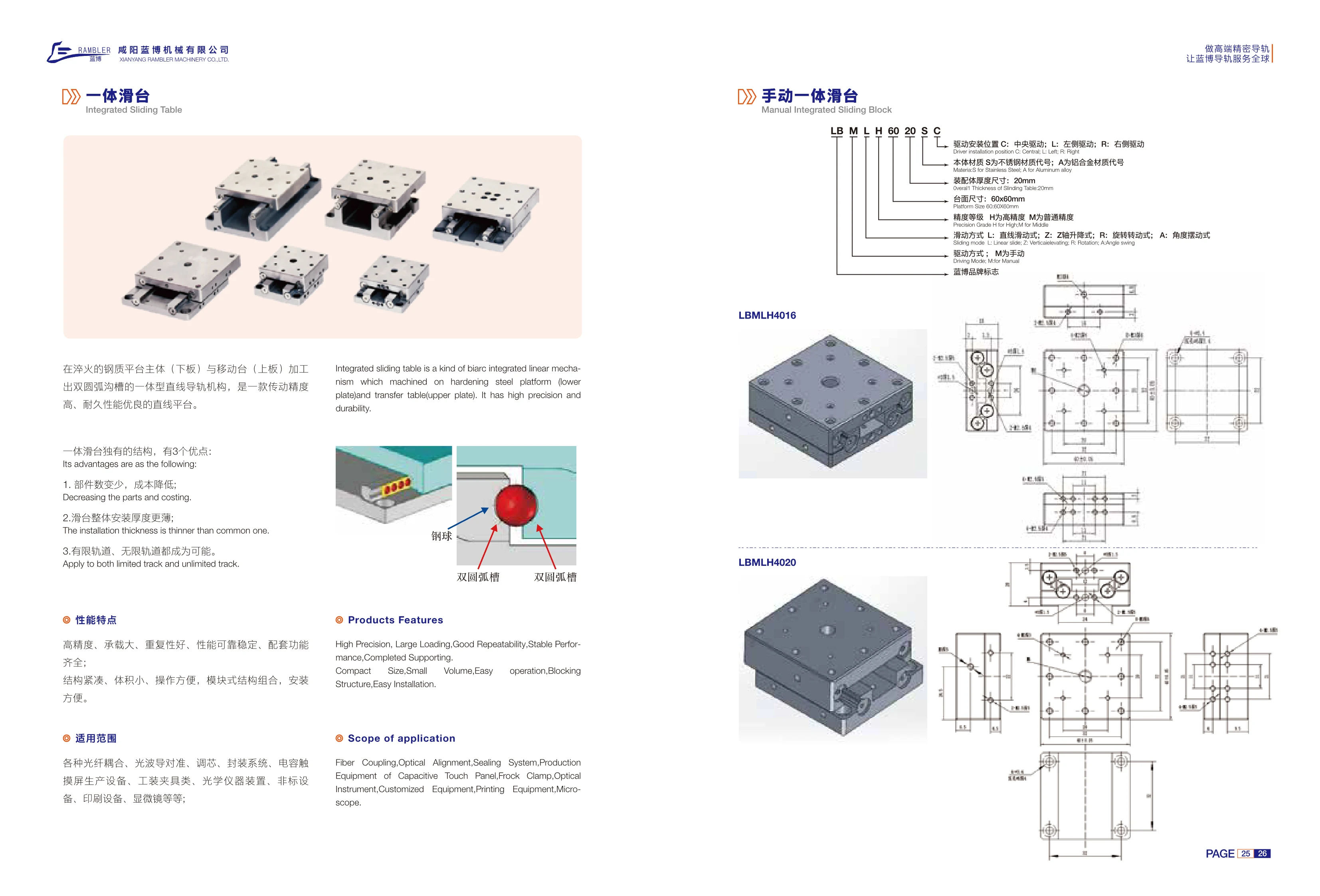
LBMH Series Manual Integrated Slide Stages
The LBMH series manual integrated slide stage is a linear guide mechanism with double-arc grooves machined directly into the hardened steel platform body (lower plate) and moving table (upper plate). Balls circulate in the double-arc grooves between the two plates, providing high motion accuracy and excellent durability. Compared with conventional modular slide stages consisting of a rail, carriage, and table, the integrated design offers three advantages: fewer components and lower cost; a thinner overall assembly; and support for both limited-travel and unlimited-travel rails. The table measures 60×60mm, and the assembly is in the 20mm thickness class. The body is available in stainless steel or aluminum alloy (code A). Selection options include drive mounting position (C center, L left, R right), accuracy grade (H high accuracy, M standard accuracy), motion type (L linear sliding, Z Z-axis lifting, R rotation, A angular oscillation), and drive type (M manual). Applications include manual fine adjustment, inspection fixtures, optical alignment, and positioning in compact automation equipment.
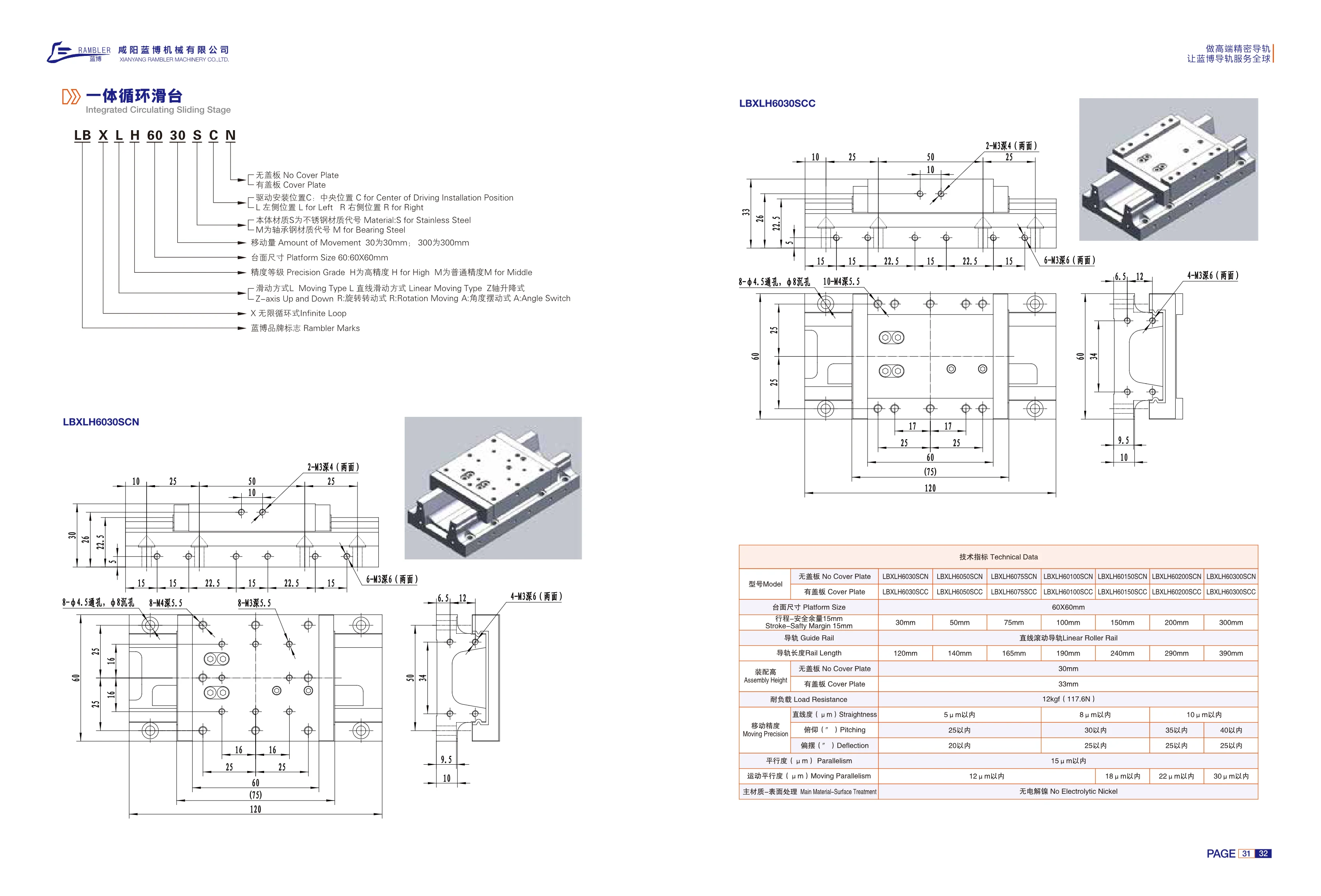
LBXLH Series Integrated Recirculating Slide
The LBXLH series integrated recirculating slide is a passive infinite-loop linear motion stage with a linear rolling guide. It has a 60×60mm platform, a travel range of 30~300mm with a 15mm safety margin, and corresponding guide rail lengths of 120~390mm. It is available with or without a cover plate, with assembly heights of approximately 33mm and 30mm respectively. Body material options are stainless steel (S) and bearing steel (M). Drive mounting positions are center (C), upper left (L), and right (R). Accuracy grades are high (H) and standard (M). Motion types include linear sliding (L), axial lifting (Z), rotary motion (R), and angular oscillation (A). The load capacity is approximately 12kgf (117.6N), straightness is within 5~10μm, and parallelism is within 15μm. The surface is electroless nickel plated. The slide is suitable for automation applications in electronics, inspection, precision assembly, and related fields.
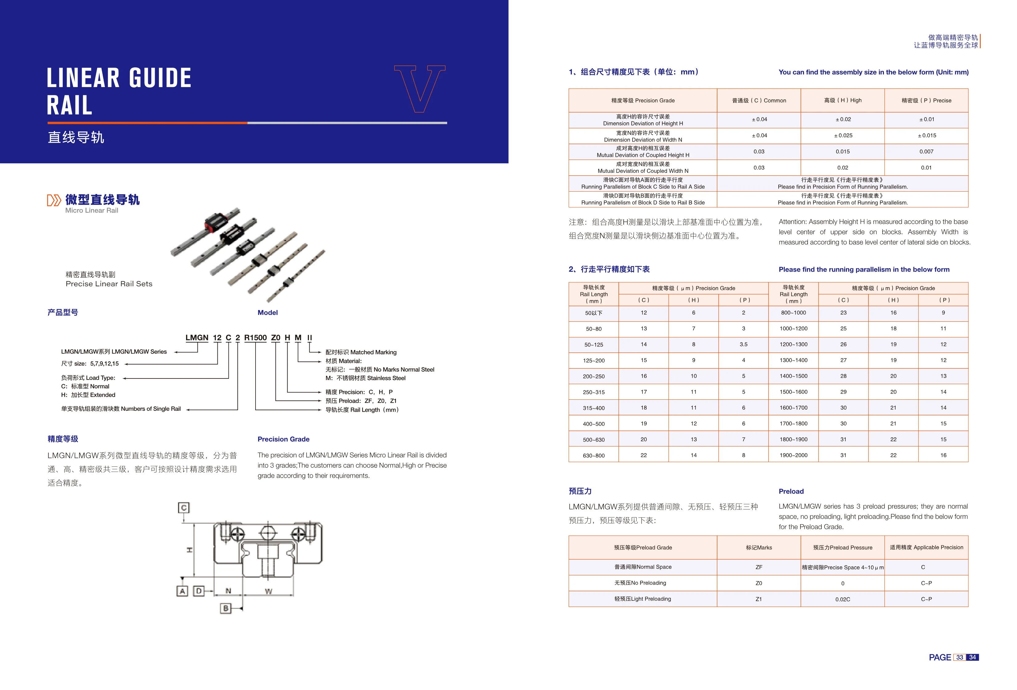
LMGN/LMGW Series Miniature Linear Guides
The LMGN/LMGW series consists of miniature precision linear guide assemblies comprising a miniature rail and carriage. They are suitable for light-load, high-precision linear guidance in compact automation equipment, semiconductor and medical equipment, inspection instruments, and similar applications. Rails are available in five sizes: 5, 7, 9, 12, and 15. Two load types are offered: C standard and H extended. Each rail can accommodate 1 or more carriages. There are three accuracy grades: normal (C), high (H), and precision (P). The respective height H tolerances are ±0.04, ±0.02, and ±0.01mm, and the width W tolerances are ±0.04, ±0.025, and ±0.015mm. The allowable height variation between paired assemblies is 0.03, 0.015, and 0.007mm, and the allowable width variation is 0.03, 0.02, and 0.01mm, respectively. For the running parallelism of carriage face C relative to rail face A and carriage face D relative to rail face B, refer to the Running Parallelism Accuracy Table for the applicable rail length. Select the appropriate size, load type, and accuracy grade based on the required design accuracy and available installation space.
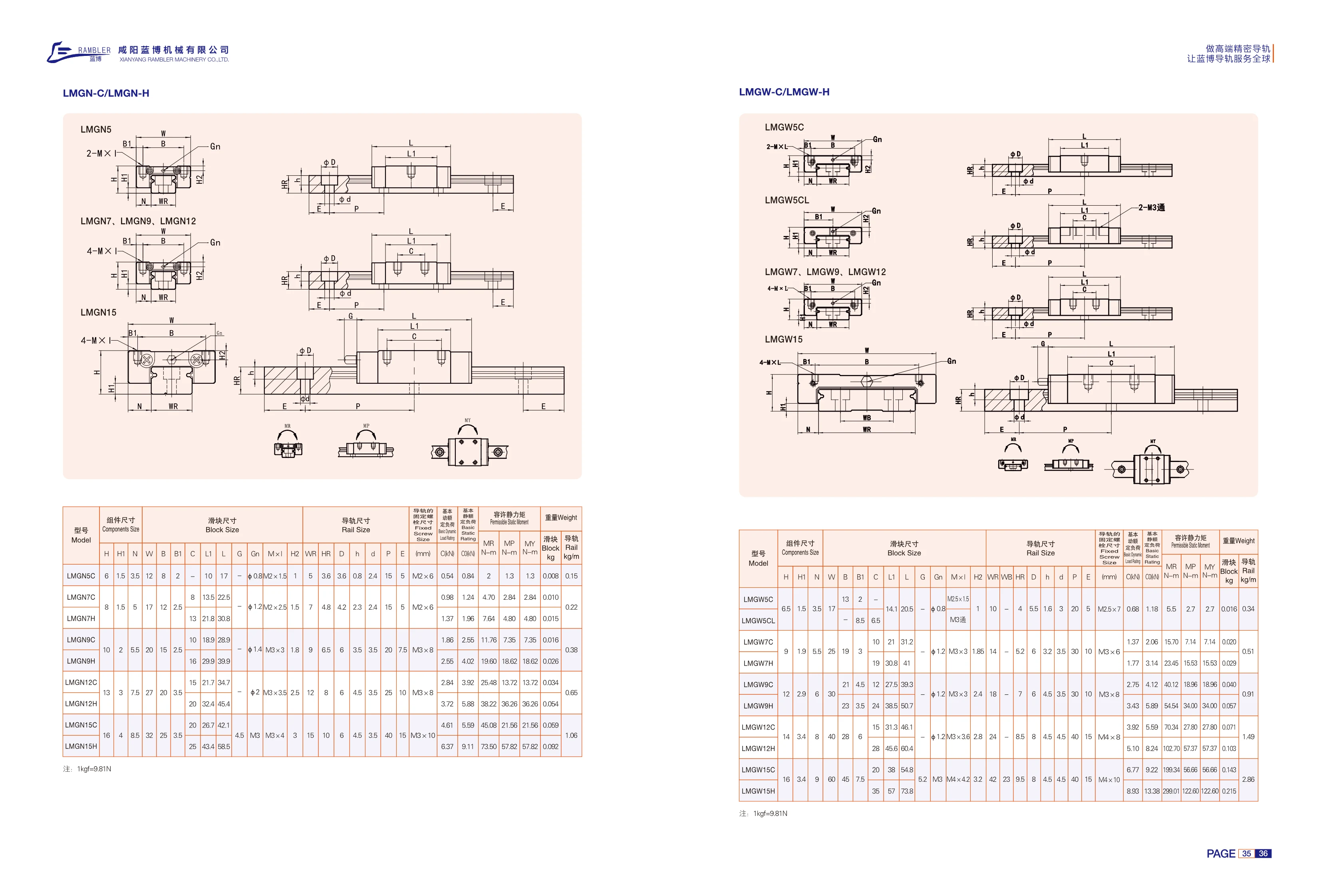
LMGW-C/LMGW-H Series Linear Guides
LMGW-C/LMGW-H miniature linear guide assemblies consist of a rail and a carriage. They use four rows of steel balls and Gothic-arch grooves with four-point contact, allowing them to withstand loads in all four directions—up, down, left and right—and provide a degree of moment resistance. The C and H types are two carriage styles and load ratings within the same series. They differ primarily in carriage length, mounting hole spacing, load ratings and permissible static moments. The compact C type has a short overall length and is suited to space-constrained applications with light to medium loads. The H type has an extended carriage, more rows of steel balls and longer effective travel, as well as higher dynamic and static load ratings and permissible static moments. It is suited to applications with longer overhangs or impact loads. The catalog specifies assembly dimensions (assembly width, mounting height and carriage mounting hole spacing), carriage dimensions (width, length, height and mounting hole thread), rail dimensions (width, height, mounting hole spacing and number of holes), rail mounting dimensions, basic dynamic and static load ratings, permissible static moments in the MA/MB/MC directions, and carriage and rail weight per meter. Select the size and carriage type based on load, moment and available mounting space, then determine the rail length and number of holes based on travel requirements.
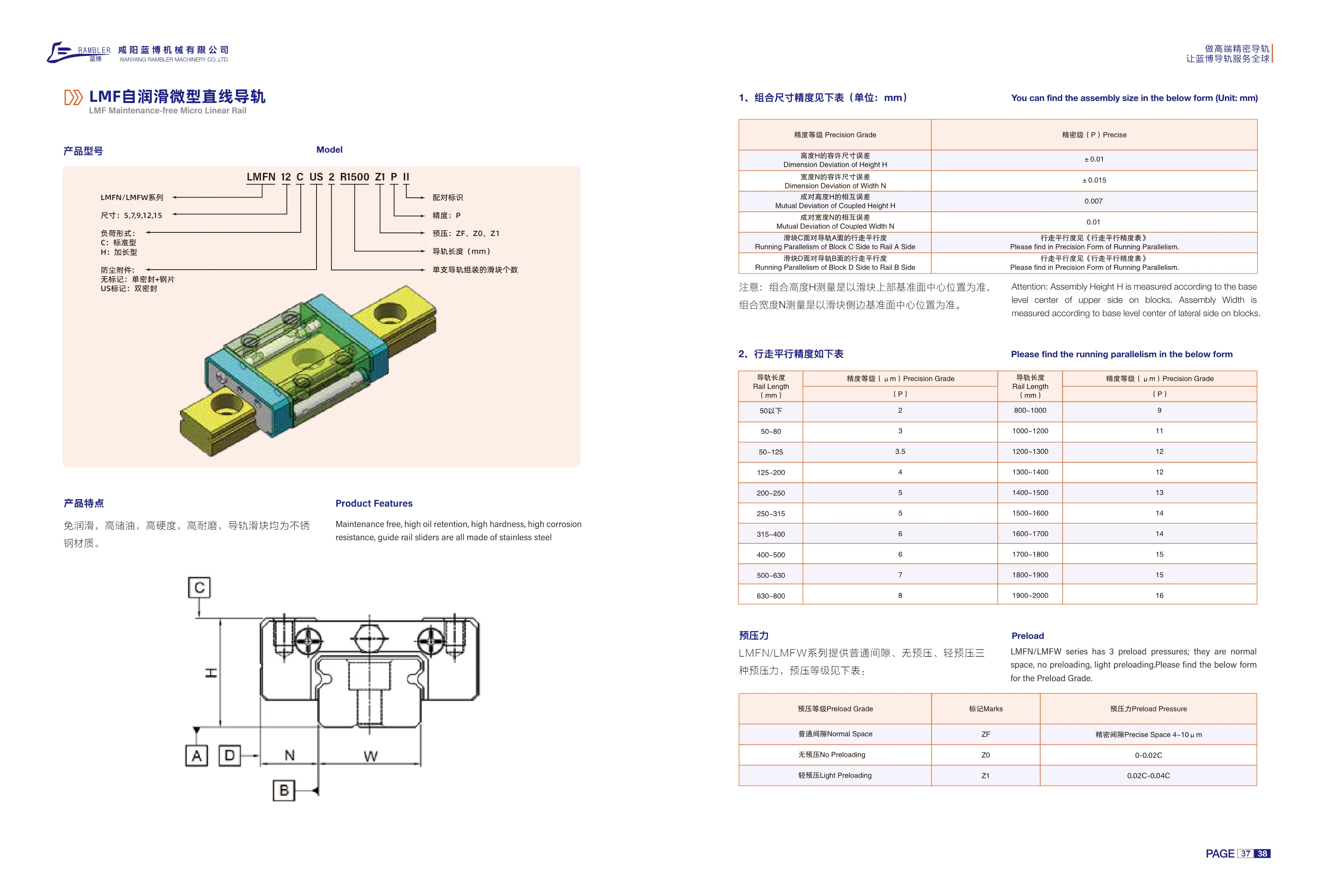
LMF Series Self-Lubricating Miniature Linear Guideways
The LMF series of self-lubricating miniature linear guideways includes two configurations, LMFN and LMFW, in five cross-sectional sizes: 5, 7, 9, 12, and 15. Blocks are available in C standard and H long load types. Dust protection options include a single seal + steel plate (no designation) or double seals (US designation). Both rails and blocks are made of stainless steel and feature lubrication-free operation, high oil retention, high hardness, wear resistance, and corrosion resistance. They are suitable for compact, low-maintenance linear guidance applications. The accuracy grade is P precision grade, with a tolerance of ±0.01 mm for assembly height H and ±0.015 mm for assembly width N. Running parallelism varies with rail length; the catalog provides a segmented accuracy table for lengths from under 50 mm to 2000 mm. Model example: LMFN 12 C US 2 R1500 Z1 P II.
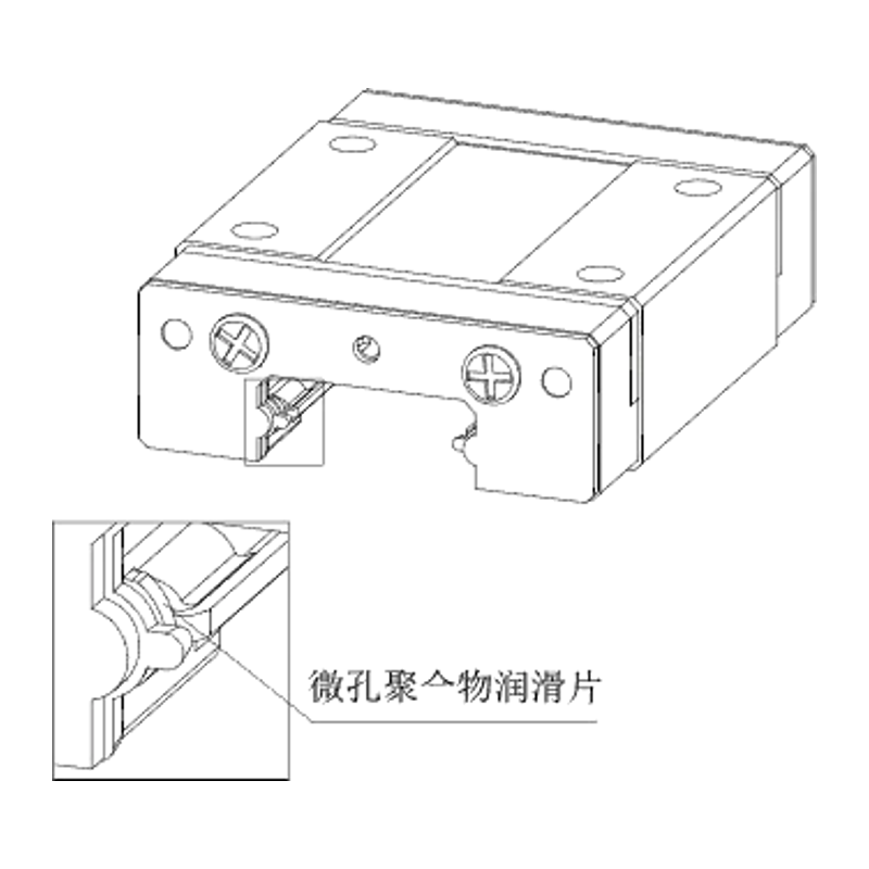
LMFN/LMFW Series Miniature Linear Guides
The LMFN/LMFW series comprises miniature linear guides: LMFN features standard blocks, while LMFW features wide blocks. They are suitable for applications requiring a low profile, light weight and high rigidity, including compact automation equipment, precision instruments, semiconductor equipment and medical devices. The catalog covers sizes 5, 7, 9, 12 and 15, with C (standard) and H (extended/high-load) block types. Dimension tables list assembly dimensions, block and rail mounting holes, basic load ratings, permissible static moments and weights, making it easy to select a model based on available space, load and moment requirements. The wider LMFW design provides greater resistance to lateral moments.
LMFN/LMFW Series Miniature Linear Guides
The LMFN/LMFW series of miniature linear guides comes in narrow (LMFN) and wide (LMFW) configurations. Model numbers consist of the series designation, size (5, 7, 9, 12, 15), and block type (C standard / H extended). Their miniature cross-section makes them suitable for space-constrained applications such as precision instruments, compact automation equipment, and semiconductor equipment. The catalog provides parameters for selection and installation, including assembly height H, block width W, block length L, rail width, rail height, mounting hole pitch, basic dynamic/static load ratings, allowable static moments (MR/MP/MY), and block and rail weights.
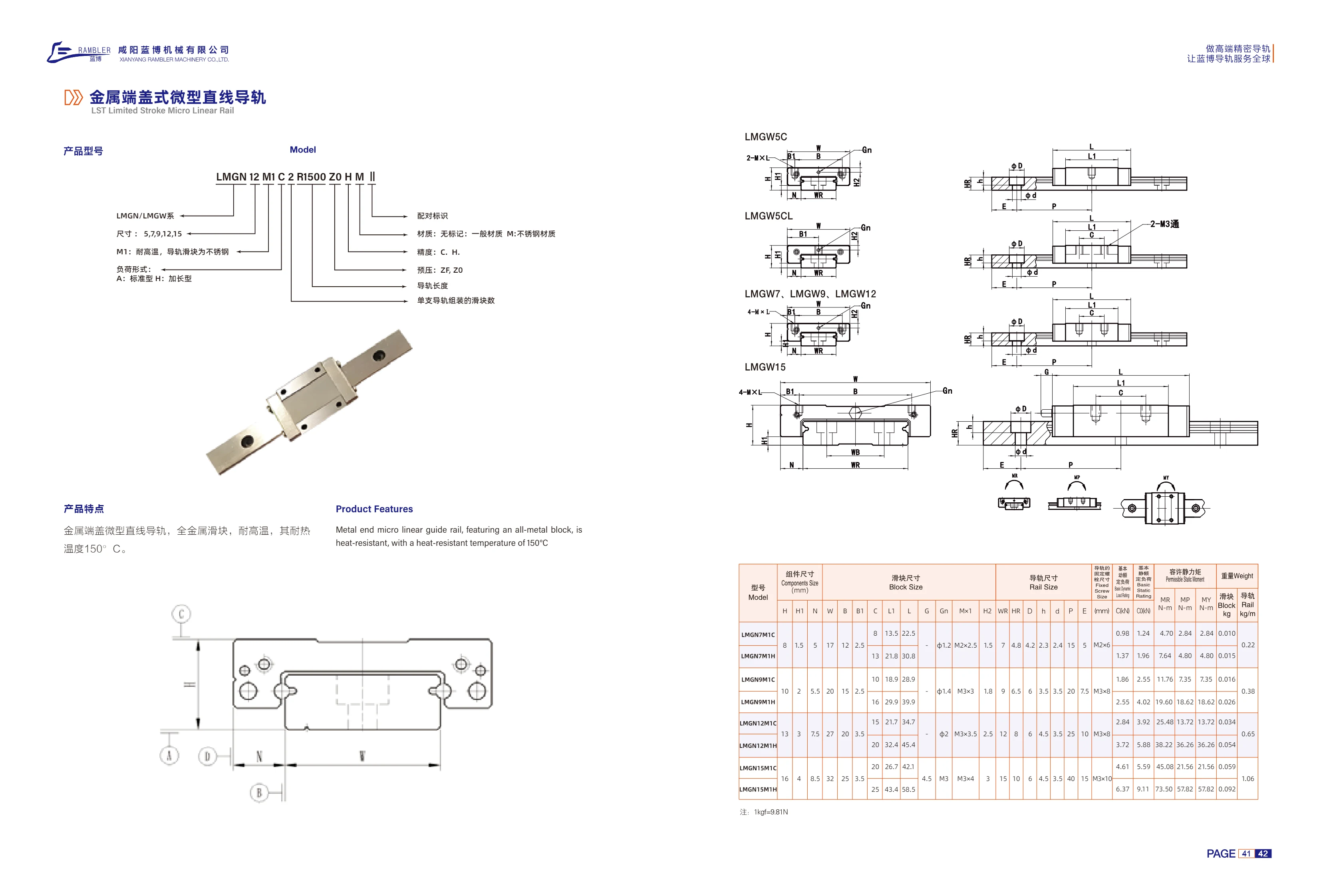
LMGN/LMGW Series Metal End Cap Miniature Linear Guides
The metal end cap miniature linear guide (LST Limited Stroke Micro Linear Rail) features an all-metal carriage and metal end caps. It withstands temperatures up to 150°C and provides precision linear guidance in harsh conditions, including high temperatures and dusty environments. The series includes LMGN and LMGW models in sizes 5, 7, 9, 12, and 15. Material options include standard material or unmarked M stainless steel. M1 is the high-temperature type, with both the rail and carriage made of stainless steel. Carriage types are A standard and H extended. Accuracy grades are C and H, and preload grades are ZF and ZO. Rail length and the number of carriages assembled on each rail can be specified as required.

LST Series Limited-Stroke Miniature Linear Guide
The LST series limited-stroke miniature linear guide features miniature blocks and a short-stroke design for precision linear guidance in confined spaces in electronic equipment, semiconductor equipment, precision instruments, and medical devices. Available sizes include 7A, 9A, 12A, and 15A, with configurations selectable by RH rail height and R rail length. Common lengths range from 36~174 mm. Accuracy grades include standard grade H, with an allowable dimensional tolerance of ±0.02 mm for height H and a paired height variation of 0.03 mm. The full ordering code can also specify preload Z1, accuracy grade C, and material M (stainless steel). Codes in parentheses in the model list, such as F8D and F12D1, are specification codes from the original text.
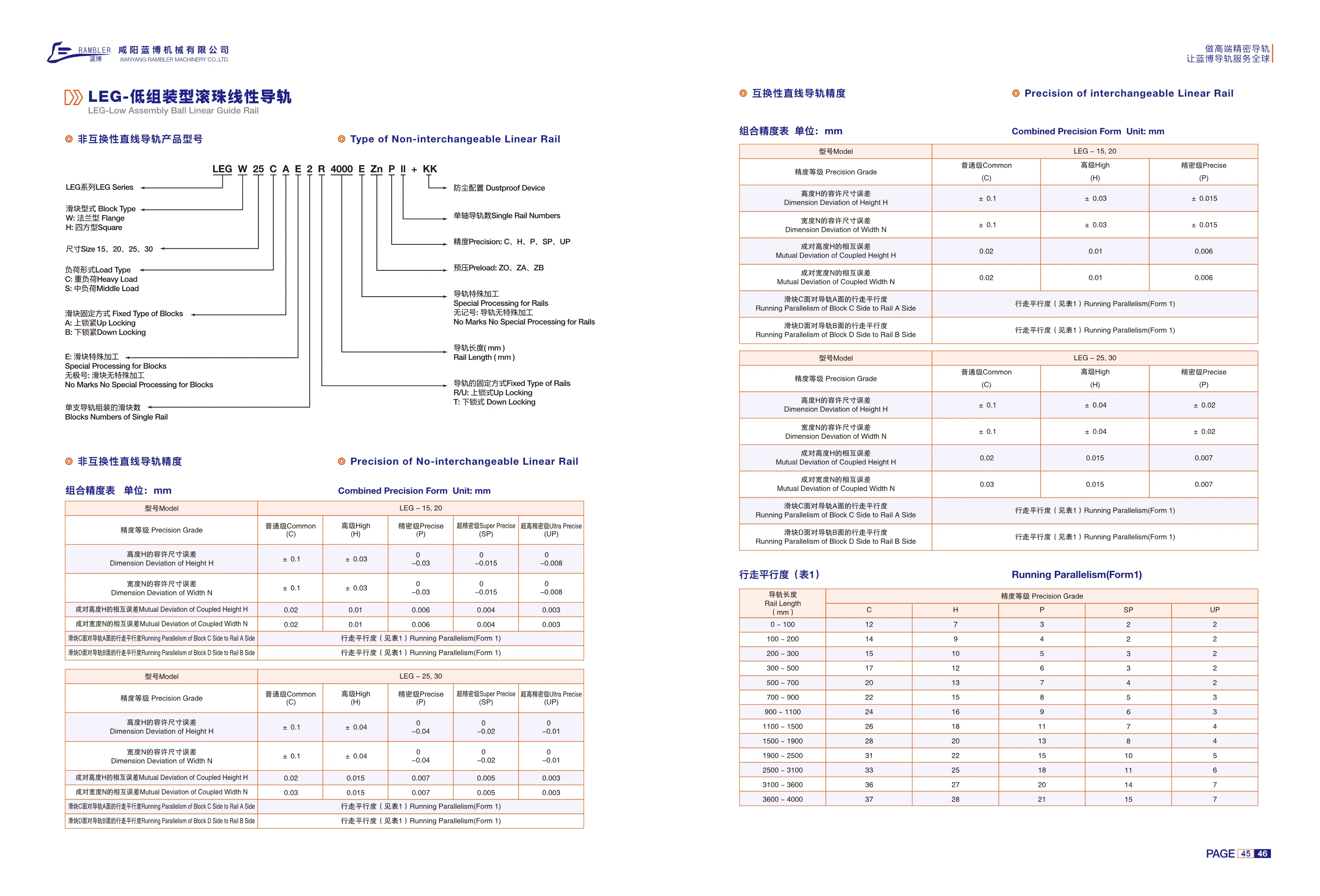
LEG Series Non-Interchangeable Linear Guides
The LEG series consists of non-interchangeable linear guides. The blocks and rails are machined and matched as sets, providing high assembly accuracy; if damaged, the entire set must be replaced. Blocks are available in flanged (W) and square (H) types, in four sizes: 15, 20, 25 and 30. Load types are heavy load (C) and medium load (S). Block mounting options are top mounting (A) and bottom mounting (B). Special block machining is also available (E; no code indicates no special machining). Accuracy grades are normal (C), high (H), precision (P), super precision (SP) and ultra precision (UP). Assembly accuracy is controlled by the permissible dimensional errors in height H and width N, as well as the differences in height and width between matched blocks. Running parallelism of block surfaces C/D relative to rail surfaces A/B is also specified in ranges according to rail length (0~4000 mm). Multiple blocks can be assembled on a single rail. Model numbers follow the sequence: block type-size-load type-mounting method-special block machining-number of blocks-rail type-rail length-special rail machining-surface treatment-accuracy grade-dust protection accessories.
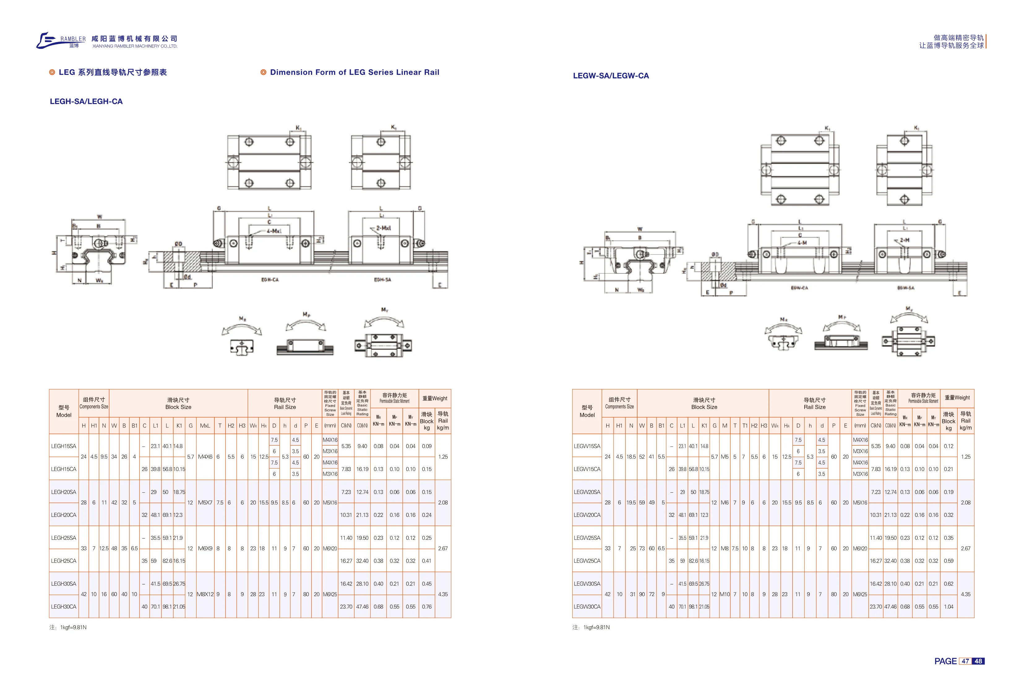
LEG Series Linear Guides
The LEG series of linear guides includes LEGH-SA, LEGH-CA, LEGW-SA, and LEGW-CA configurations for linear guidance and load support in automation equipment. The catalog provides selection parameters including assembly dimensions, block dimensions, rail dimensions, mounting bolt sizes, basic static friction coefficient (as stated in the source), allowable static moment, and weight. LEGH and LEGW denote different rail and block cross-section series, while SA and CA indicate different block mounting styles. Select the specific model from the dimensional reference table based on the available installation space, load direction, and moment conditions.
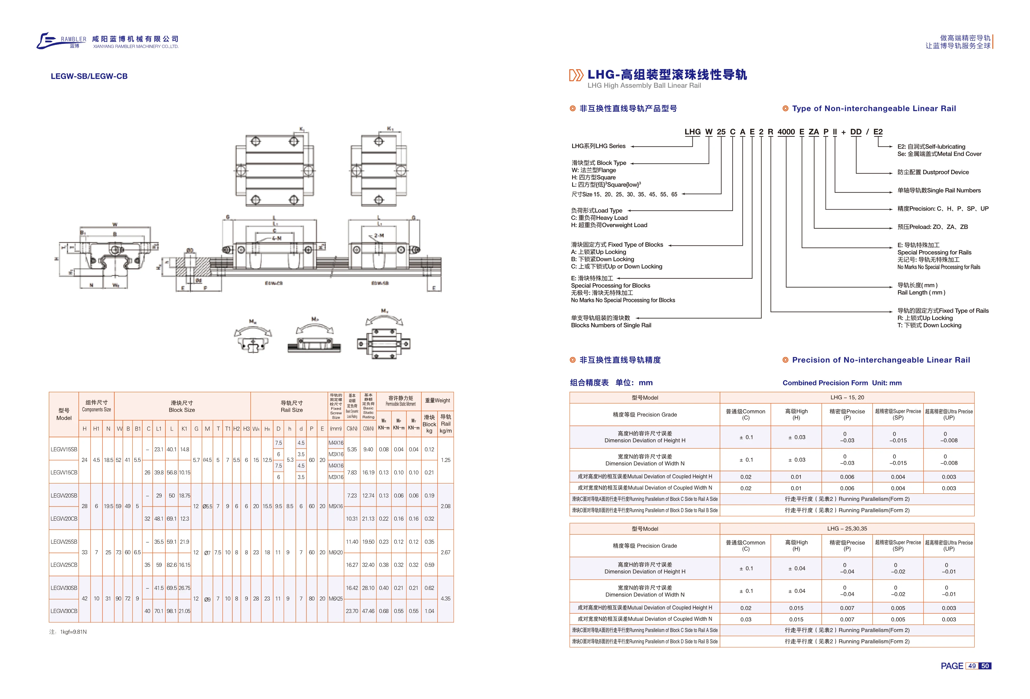
LHG Series Linear Guides
The LHG series comprises non-interchangeable linear guides with block and rail assemblies. Common configurations include LHGHA-CA and LHGHA. Products are available in five accuracy grades: normal C, high H, precision P, super precision SP, and ultra precision UP. Each grade specifies tolerances for height H and width N, variations in height and width between paired assemblies, and the running parallelism of the block relative to the rail. The dimension tables cover assembly, block, and rail dimensions, including H, H1, N, W, B, B1, C, L, L1, K, G, MxL, T, H2, H3, W, Hr, D, h, d, P, and E. These guides are suitable for automated equipment, precision machine tools, and linear motion mechanisms.
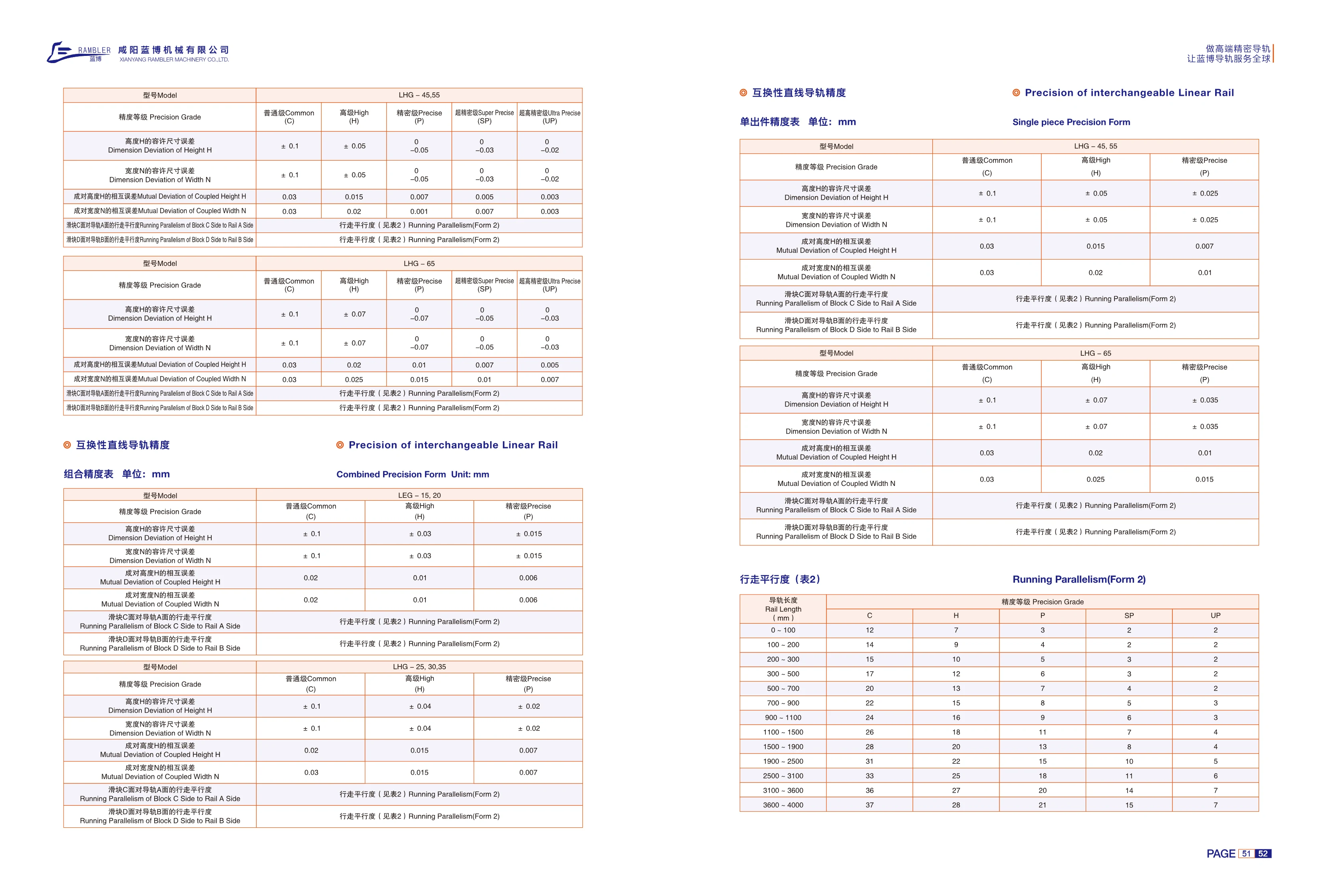
LHG Series Interchangeable Linear Guides
LHG series interchangeable linear guides feature freely interchangeable rails and blocks for easy maintenance, replacement and inventory management. Six cross-sectional sizes are available: 25, 30, 35, 45, 55 and 65. There are five accuracy grades: normal C, high H, precision P, ultra-precision SP and ultra-precision UP. Individual component accuracy is controlled by the dimensional tolerances for height H and width N: both are ±0.1 mm for normal grade, ±0.04~±0.07 mm for high grade, and 0 for precision grade and above. When used in pairs, allowable variation is reduced according to grade: paired height variation decreases from 0.02~0.03 mm to 0.005 mm, and paired width variation decreases from 0.03 mm to 0.005~0.007 mm. Running parallelism between block surface C and rail surface A, and between block surface D and rail surface B, is specified in Table 2 by rail length from 0~4000 mm. Longer rails have higher allowable values, while higher accuracy grades have lower allowable values. These guides are suitable for machine tools, automation equipment, semiconductor equipment and other applications requiring accurate travel and easy maintenance through interchangeability.
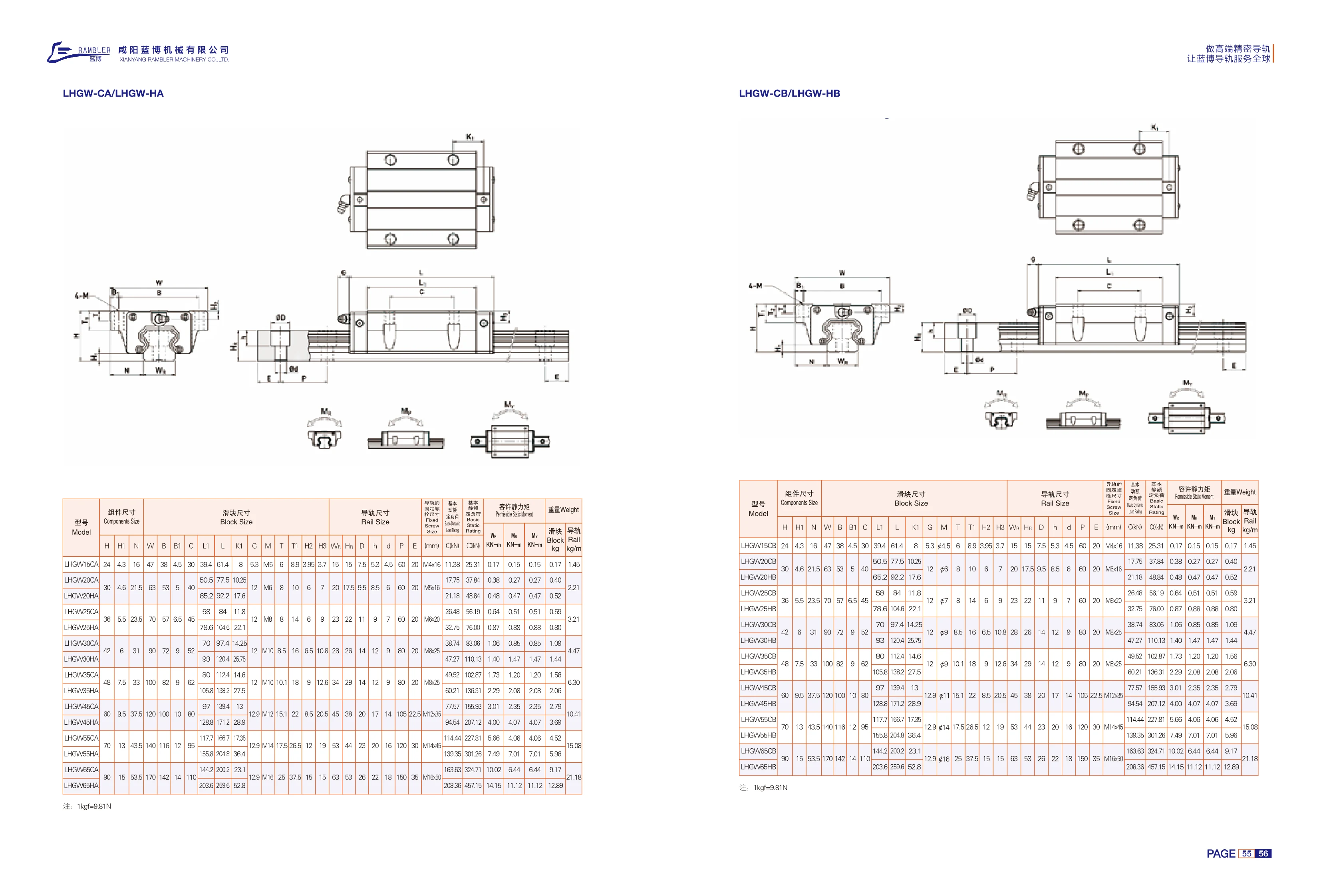
LHGW-CA/LHGW-HA Series Linear Guides
The LHGW-CA/LHGW-HA series consists of four-row ball linear guides with a low-profile assembly. Blocks are available in two configurations: CA (standard) and HA (extended, high-load capacity), in nominal sizes 15/20/25/30/35/45/50/55/60. The guides use four rows of steel balls with a 45° contact angle, allowing them to withstand radial, reverse radial and lateral loads simultaneously. They offer high rigidity, low friction and smooth, easy movement. The blocks and rails are interchangeable and provide linear guidance for machine tools, automated machinery, semiconductor equipment and medical devices. The catalog lists assembly dimensions (H, H1, N, V, B, B1, C, L1, L, K1, etc.), rail dimensions (Wn, Hn, D, h, d, P, E, etc.), mounting bolt sizes, basic static friction coefficient, allowable static moments and weight. Select a model according to load, travel, installation space and accuracy grade.

SYX-S Series Linear Guide Rails
The SYX-S series comprises high-performance linear guide block assemblies designed for high-precision linear motion in automation equipment. It includes several subtypes—standard (BN), extended (BL), compact (BS), flange (FS), and standard flange (FN)—to accommodate different installation spaces and load requirements. The range covers 10 sizes, from 515 to 555, with block widths of 24–70 mm, dynamic load ratings of 11.38–114.44 kN, and static load ratings of 16.97–148.33 kN. The rails are made of high-carbon steel and precision-ground, while the blocks contain rolling steel balls for low friction, high rigidity, and long service life. The products offer full dimensional interchangeability, with mounting-hole spacing and reference surfaces strictly standardized.

SYX-H Series Linear Guide Rails
The SYX-H series linear guide assemblies are available in two models: SYX-H-FN and SYX-H-FL. Designed for precision linear motion in automation equipment, they offer high rigidity and load capacity. For detailed dimensions, see the model list.

HGH Series Linear Guideways
HGH Series linear guideways feature a high-assembly, square-block design with high rigidity and load capacity. They are suitable for applications requiring precise linear motion, such as automation equipment and machine tools. The series is available in a range of sizes, with block and rail dimensions varying by model. Its compact design makes installation easy, and it is widely used in industrial automation.

HGL Series Linear Guide Rails
The HGL Series linear guide rails feature a high-assembly, square design with high rigidity and load capacity, making them suitable for heavy-duty applications such as automation equipment and machine tools. The series offers two carriage styles—standard (CA) and high (HA)—to meet different installation requirements. Made from high-quality steel and precision-ground, the rails ensure high accuracy and smooth operation. Recirculating balls inside the carriages enable low-friction linear motion. A range of sizes is available, and rail lengths can be customized to customer requirements.

HGW Series Linear Guideways
The HGW Series features high-assembly flange-type linear guideways with two carriage styles: HGW-CC and HGW-HC. Designed for heavy loads and high rigidity, the series delivers high-precision linear motion and is widely used in CNC machine tools, automation equipment, precision machinery, and other applications. For detailed dimensions, refer to the dimensional tables in the product catalog.
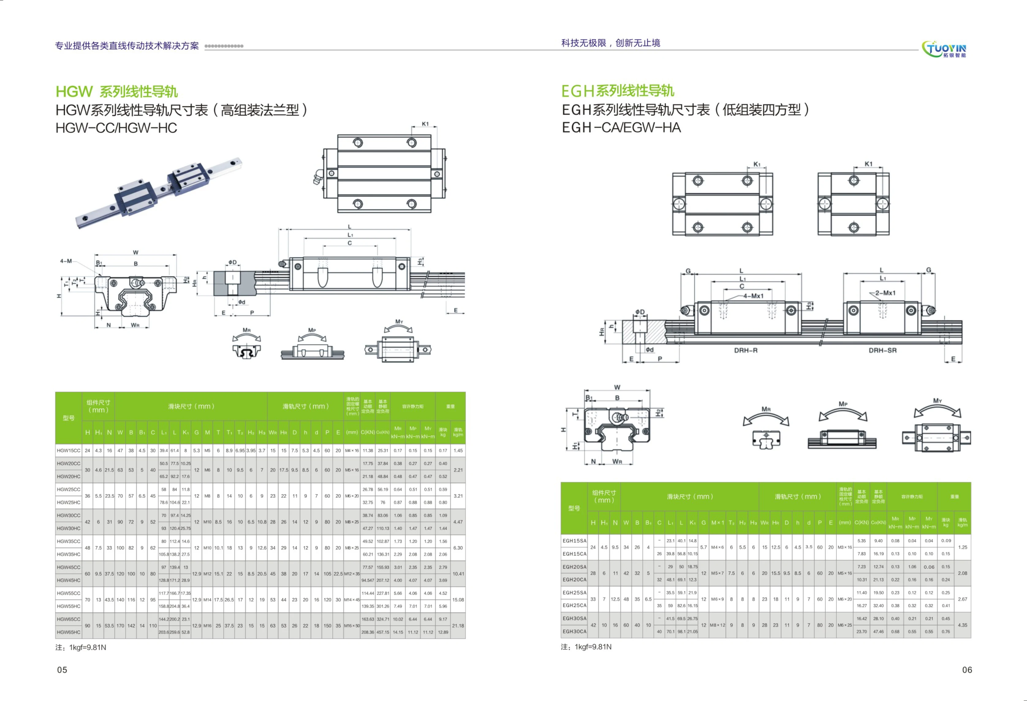
EGH Series Linear Guideways
The EGH series is a low-profile, square-type linear guideway featuring high-quality steel blocks and rails. It offers high rigidity, high precision, low noise, and a long service life. This series is suitable for applications requiring precise linear motion, such as automation equipment, CNC machine tools, and precision inspection instruments. The EGH series includes two main block types: EGH-CA (square block) and EGW-HA (wide block), meeting a range of load and installation requirements. Rail widths are available in sizes from 15 mm to 65 mm. Preload options include light, medium, and heavy, while accuracy grades are standard (N), high (H), and precision (P). The guides are secured with bolts and offer a choice of seals to suit different operating environments. Standard lengths range from 100 mm to 4,000 mm, with custom lengths available on request. The EGH series features an optimized internal recirculation design that reduces running resistance and improves travel speed and acceleration performance, making it an important drive component in industrial automation.
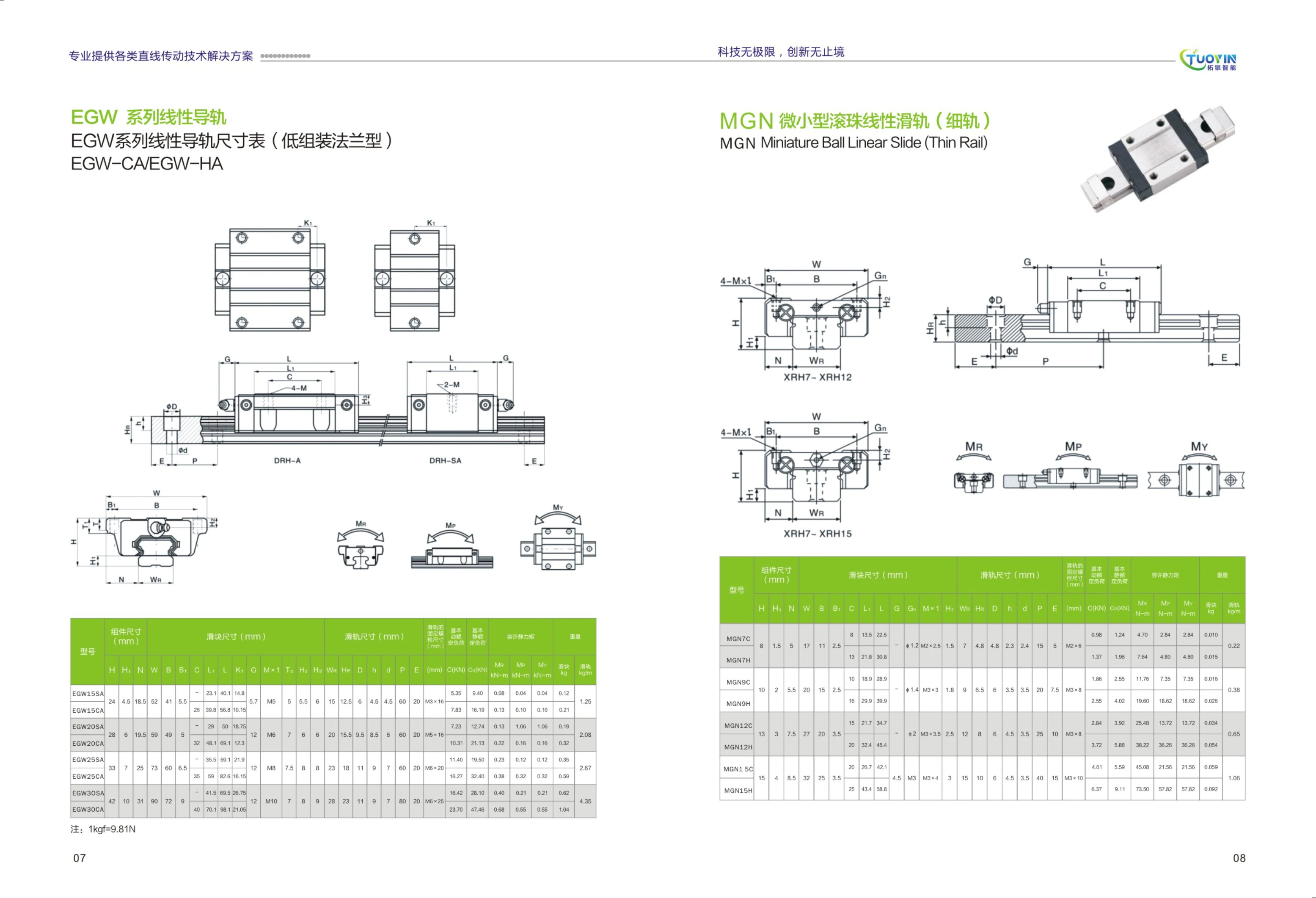
EGW Series Linear Guideways
EGW Series linear guideways feature a low-profile, flange-type design and are available with two carriage types: EGW-CA and EGW-HA. They are suited to applications requiring high-precision linear motion, such as automation equipment and industrial machinery. With a low mounting height and high load capacity, this series is widely used in CNC machine tools, electronic equipment, semiconductor manufacturing, and other fields. Refer to the product catalog for detailed dimensions.

MGN Miniature Ball Linear Guide Rails
The MGN series comprises miniature ball linear guide rails (narrow rails) designed for precision linear motion in space-constrained applications. Available in several rail widths (7 mm, 9 mm, 12 mm, and 15 mm) and two carriage types (C standard and H extended), they offer high precision, high rigidity, and low friction. The rails and carriages are made from high-quality bearing steel, and the carriages feature recirculating balls for smooth motion. Specifications include overall height and width, basic dynamic and static load ratings, static moment ratings, and weight, meeting the needs of precision positioning under light loads.

MGW Miniature Wide-Type Ball Linear Guideway
The MGW series comprises miniature wide-type ball linear guideways designed for automation equipment requiring high-precision linear motion. Featuring a recirculating ball design, these guideways offer low friction, high rigidity, and high load capacity. Available in a range of specifications, they have a wider rail profile, making them ideal for space-constrained applications that demand high stability. They are widely used in automation fields such as semiconductor equipment, medical instruments, precision measuring instruments, and electronics manufacturing.
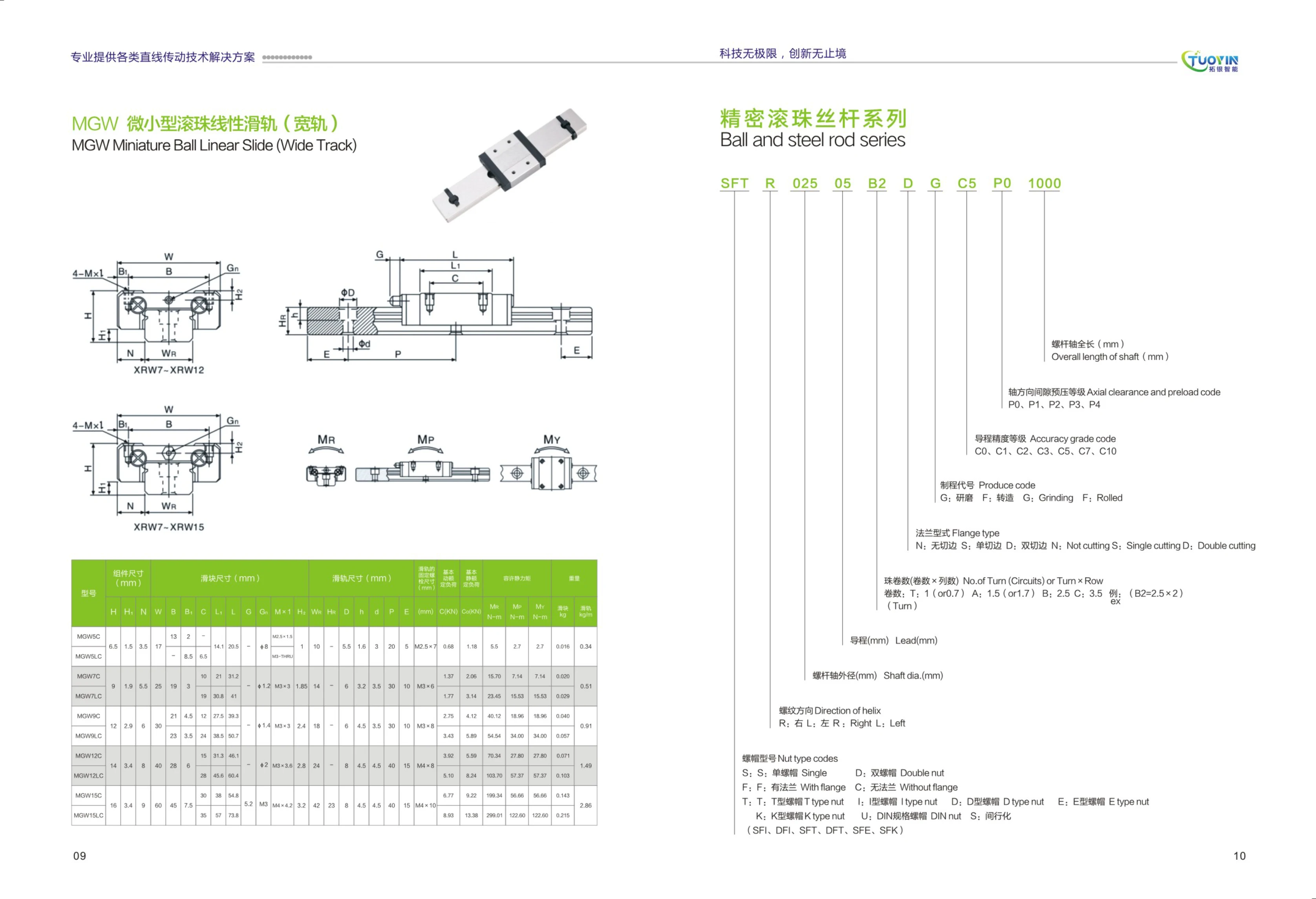
SFT Ball Screw
The SFT series consists of precision ball screws designed for high-accuracy linear motion applications. The model code specifies the thread direction (R/L), screw diameter (mm), lead (mm), number of ball turns (turns × rows; for example, B2 means 2.5 turns × 2 rows), flange type (N: no cut; S: single cut; D: double cut), process code (G: ground; F: cast), lead accuracy grade (C0–C10), axial clearance/preload grade (P0–P4), and overall screw shaft length (mm). The series is widely used in automation equipment, machine tools, semiconductor equipment, and other fields.
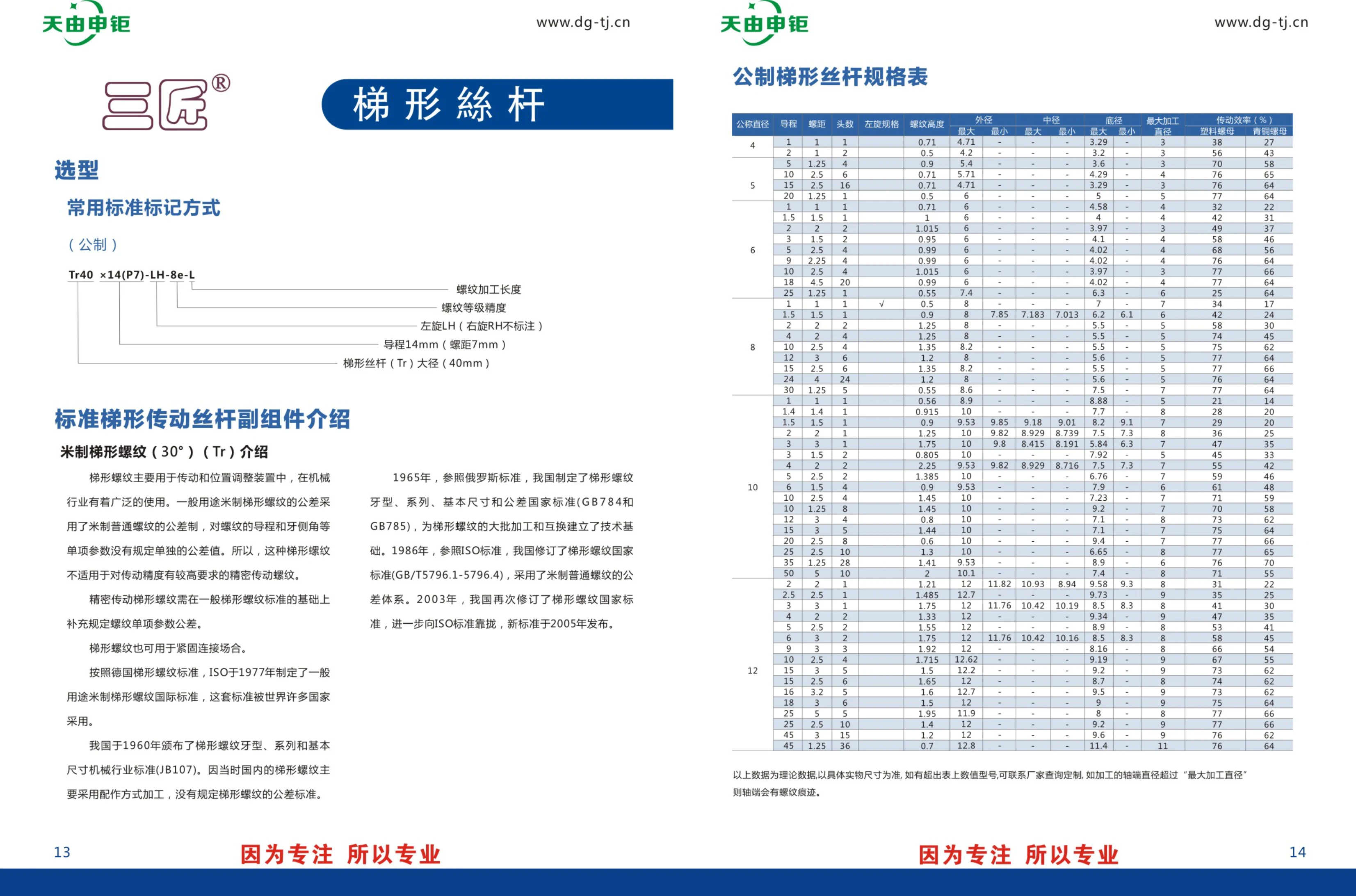
Standard Trapezoidal Lead Screw and Nut Assembly
This standard trapezoidal lead screw and nut assembly uses metric trapezoidal threads with a 30° flank angle and is primarily designed for power transmission and positioning applications. Nominal screw diameters range from 4 mm to 50 mm, with custom sizes also available. A variety of lead, pitch, and thread-start combinations are offered, including left-hand threads. The screws are manufactured to ISO and Chinese national standard GB/T 5796. General-purpose trapezoidal threads use the metric general-purpose thread tolerance system. Matching nuts are available in non-flanged, round-flange, and double-sided cut-flange styles, with dynamic permissible thrust loads ranging from 1.47 kN to 12.36 kN. Custom machining is available; please contact the manufacturer for sizes not listed in the table.
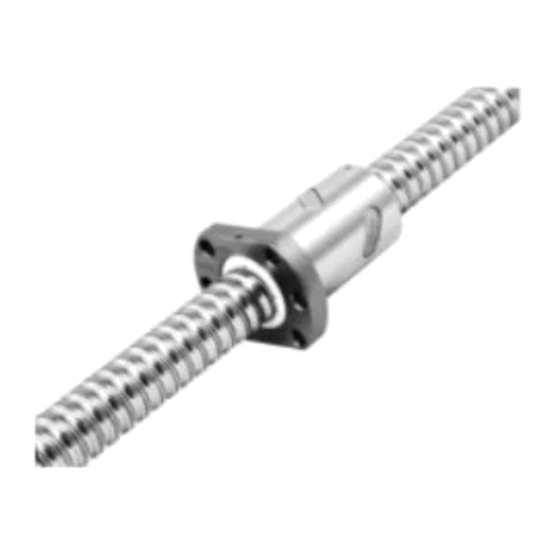
SFU Series Ball Screws
SFU series ball screws comply with DIN 69051 Form B and feature a recirculating nut design for high-precision linear motion. The range includes various shaft diameters (12–50 mm) and leads (4–20 mm), with different ball diameters and circuit counts to meet a wide range of load and speed requirements. The table lists the dynamic and static load ratings and stiffness specifications for each model. These screws are widely used in CNC machine tools, automation equipment, precision positioning systems, and other applications.