Linear Motion Accessories — Page 8
LF-MEA Series High-Precision Miniature Linear Electric Actuators
The LF-MEA series high-precision miniature linear electric actuators are compact electric actuators with integrated drive and control. They mount via the front or rear end cap and offer strokes of 8~20mm and maximum thrusts of 30~400N. They support Modbus RTU(RS485) and CAN bus communication, with rated voltages of DC12V±10%/DC24V±10% and repeat positioning accuracy up to ±3μm (±2μm optional). Some models can be equipped with an optional integrated force sensor (resolution ±0.1%FS) for precise force control and press-fit operations. The compact units measure as little as approximately 20×12×105.5mm and weigh from 0.12kg. Depending on the model, no-load and full-load speeds range from 1~33mm/s. They are rated IP40 and operate at 0~55℃ and below 85%RH, making them suitable for automated electronics assembly, precision dispensing, inspection, and other applications.
LF Series Miniature Linear Electric Actuators
The LF series is LENFOR's range of miniature linear electric actuators, integrating a drive motor, lead screw and position feedback into one unit. They are designed for short-stroke, high-precision pushing and positioning applications, including 3C electronics assembly, semiconductor and lithium battery testing, and medical and laboratory automation. The range comprises five product series by application: M (Mini), L (Large), E (Electronic), A (Actuator) and F (Force moment). Body widths of 0-99 mm and strokes of 001-999 mm are available. Supported communication methods include PWM, Modbus RTU (RS485), I/O (NPN/PNP) and CAN. Four accuracy grades are available: 0-5, 11-20, 31-40 and 41-50 μm. Options include different speed grades, with or without a holding brake, and mounting on the front end cap (default), on the side, or using fixing holes on a flat surface. Standard dimensions apply by default; a customer code must be added for customized versions. A 28AWG cable is supplied as standard, with wires designated RS485A (white), R
LF-M Mini Linear Electric Actuator
The LF-M Mini linear electric actuator is a high-precision miniature electric actuator in the LF-LENFOR series. Its model code follows a defined naming convention. It has a width range of 0-99mm and a stroke range of 1-999mm, and supports communication methods including TTL/PWM. It offers accuracy grade A (0-5μm), speed grade E (31-40mm/s), an optional holding brake, and front end cap mounting as standard. Its compact size makes it suitable for small automated equipment, precision positioning, laboratory instruments, and other applications. Dimensions can be customized to customer requirements.
LF-L Large Linear Actuator
The LF-L is the Large series in the LENFOR (LF) linear actuator family. It converts motor rotation into high-rigidity linear pushing and pulling motion and can replace conventional pneumatic cylinder and guide rail assemblies. It is widely used for pressing, lifting, and material handling in electronics assembly, lithium battery, photovoltaic, packaging, and inspection equipment. The series follows an ordering code: the company/brand code LF comes first, followed by the product series code (M=Mini, L=Large, E=Electronic, A=Actuator, F=Force moment), then width (mm, 0~99), stroke (mm, 001~999), communication method (TTL, PWM, Modbus RTU/RS485, I/O NPN or PNP, CAN), accuracy grade (μm ranges, such as 0~5, 11~20, 31~40, 41~50), speed grade (mm/s ranges, such as 6~10, 31~40), brake function (B series, optional Brake), and mounting method (D for default front end cap mounting
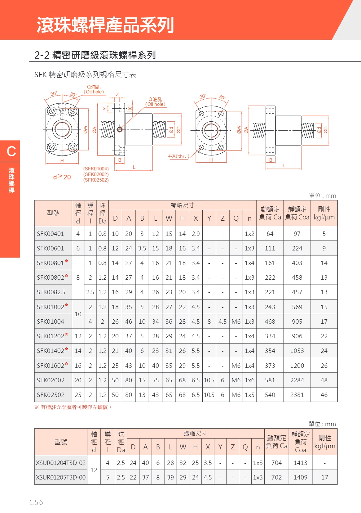
SFK Ball Screw Series
The SFK series of ball screws is available in two accuracy grades: precision-ground and rolled. A variety of shaft diameter and lead combinations are offered. Shaft diameters range from 4 mm to 25 mm, and leads from 1 mm to 4 mm. Using high-precision balls, these screws have a dynamic load rating of up to 581 kgf, a static load rating of up to 2,381 kgf, and stiffness of up to 48 kgf/μm. They are suitable for applications requiring high-precision linear transmission, such as automation equipment and precision machinery. Model numbers consist of “SFK” followed by a three-digit shaft diameter and a two-digit lead (including the decimal point). For example, SFK00802 indicates a shaft diameter of 8 mm and a lead of 2 mm. Left-hand threads are available for some models.
LF-E Series Electronic Electric Cylinders
LENFOR(LF) series electric cylinders/linear electric actuators use a modular alphanumeric naming system covering five sub-series: miniature (M), large (L), electronic (E), electric cylinder (A), and torque (F). Built around high-precision miniature linear motion, the products offer widths of 0-99mm and strokes of 1-999mm. Communication options include TTL, PWM, ModbusRTU(RS485), I/O(NPN/PNP), and CAN. Accuracy grades are 0-5μm, 11-20μm, 31-40μm, and 41-50μm, while speed grades are 31-40mm/s and 6-10mm/s. A holding brake is also available. Mounting options include the standard front end cap and mounting holes on the side or flat surface. No dimension specification is included by default; a customer code is appended for customized versions. Suitable for automation applications such as electronics assembly and precision positioning.
LF Series Electric Cylinders
The LENFOR LF Series comprises high-precision electric cylinders and linear actuators, including Mini, Large, Electronic, Actuator, and Force moment subseries. Product widths range from 0–99 mm, with strokes of 001–999 mm and thrust up to tens of newtons. Multiple communication options are supported, including TTL, PWM, Modbus RTU (RS485), I/O (NPN/PNP), and CAN. Accuracy grades include 0–5 μm, 11–20 μm, 31–40 μm, and 41–50 μm, while speed grades are 6–10 mm/s and 31–40 mm/s. A holding brake is optional and is not included by default. Mounting options include the standard front end cover, side mounting, and flat-surface mounting via fixing holes. Dimensions and specifications can be customized to customer codes. Applications include precision positioning, electronics assembly, semiconductors, and medical automation.
LF-F Torque Series Electric Cylinders
The LF-F Torque Series is a range of LENFOR(LF) linear electric cylinders using torque control for automated applications requiring precise force control. The series supports widths of 0-99mm and strokes of 001-999mm, with a choice of T-TTL or C-CAN communication. It has an accuracy grade of F(41-50μm) and a speed grade of E(6-10mm/s). Optional features include a holding brake(B) and mounting holes on a flat surface(P). No dimensional specification is provided by default; dimensions can be customized to customer requirements with a customer code appended. Applications include electronics assembly, precision positioning, and force-controlled press fitting.
FVR Series Crossed Roller Guides
FVR series crossed roller guides use precision rollers arranged at right angles in a roller cage and running on V-grooved surfaces in dedicated rails. Two rows of roller guides mounted in parallel can support loads from 4 directions. Preload can be applied to provide clearance-free, highly rigid linear guidance with smooth, light movement. The unique roller retention method increases the effective roller contact length by approximately 1.7 times compared with conventional products. A shorter pitch and more rollers provide approximately 2 times greater rigidity and 6 times longer service life, along with excellent lubricant retention, low friction, and smooth motion. Two accuracy grades are available: high grade (H) and precision grade (P). The H grade has a height tolerance of ±0.02 and a matched-pair variation of 0.01; the P grade has a tolerance of ±0.01 and a matched-pair variation of 0.005. Nominal models FVR1~FVR9 correspond to different roller diameters and can be selected by roller diameter, rail length, accuracy grade, and ball count. One set consists of 4 rails and 2 cages. These guides are widely used in the sliding sections of office equipment, measuring instruments, printed circuit board drilling machines, optical instruments, and X-ray equipment.
XSUR Series Ball Screws
XSUR Series precision-ground ball screws are designed for high-precision linear drive applications. The series offers high rigidity, high load capacity, and consistent lead accuracy. Typical models include a 12 mm shaft diameter with 4 mm and 5 mm leads. The dynamic load rating is approximately 700 kgf, the static load rating is approximately 1,400 kgf, and rigidity is approximately 17 kgf/μm. The nut features a compact design and supports multiple mounting options. These ball screws are widely used in automation equipment, precision machine tools, semiconductor manufacturing, and other fields.
FVRT-A Series Crossed-Roller Guide Tables
The FVRT-A series is an integrated precision table built around a pair of crossed-roller guides. It consists of a base, table, roller cage and stop screws. Cylindrical rollers arranged at 90° to each other guide the table along the base, while a cage separates the rollers. This design provides short-travel, high-rigidity, low-friction linear motion while supporting combined loads in the vertical and horizontal directions. Both the table and base have countersunk mounting holes, allowing the base to be screwed to a frame and the workpiece to be secured to the table. Stop screws at both ends of travel limit the sliding range, prevent the roller cage from falling out and allow preload adjustment during assembly. The series is suited to applications requiring light loads, high precision and a compact design, such as optical inspection, precision measurement, manual fine-adjustment stages and small automated positioning mechanisms. Models can be selected according to the required travel, table size and mounting hole positions.
FVRU Series Standard Crossed Roller Guides
The FVRU series consists of standard crossed roller guides with a crossed roller and cage design, suitable for precision guidance applications requiring high rigidity and smooth linear motion. The standard table and base are made of aluminum alloy, while the rails and rollers are made of Gcr15 bearing steel. Rail hardness is HRC58 or higher, roller hardness is HRC60 or higher, and the cage is made of SUS304. The model designation consists of the nominal model FVRU, roller diameter, and slide length. Suffixes may be added, including N (45# steel with electroless nickel plating) and A (countersunk holes in the base). If no suffix is specified, the unit has a black anodized aluminum alloy construction and upward-facing threaded holes in the base.
FVRT Series Ultra-Compact Crossed Roller Guides
The FVRT series is FARAY's ultra-compact crossed roller guide, featuring rollers arranged at 90° to each other in a SUS304 cage. This rolling structure supports radial and reverse-radial loads in four directions as well as moments within a minimal installation space, providing high-rigidity, high-precision linear guidance for short strokes. The slide table is made of 45# steel, while the base, rails and rollers are made of Gcr15 bearing steel. The rails have a hardness of HRC58 or higher, the rollers HRC60 or higher, and the cage is made of SUS304 stainless steel. The series is suitable for light-load, high-precision applications such as compact precision equipment, optical and semiconductor devices, measuring instruments and electronics assembly stations. Surface finish options: no marking indicates black oxide, while N indicates electroless nickel plating. Base mounting hole options: no marking indicates upward-facing threaded holes in the base, while A indicates upward-facing countersunk holes in the base. The model code combines the nominal model, roller diameter and slide table length. Select the specification according to the available installation space, stroke and load requirements.
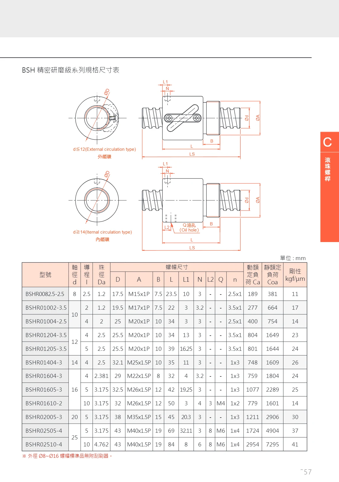
BSHS Series Ball Screws
The BSHS series precision-ground ball screws are available in a range of shaft diameter and lead combinations for high-precision positioning and power transmission. Model numbers begin with BSHR, followed by parameters such as shaft diameter, lead, and ball diameter. The table lists specifications with shaft diameters from 8 mm to 25 mm, leads from 2.5 mm to 10 mm, and ball diameters from 1.2 mm to 4.762 mm, along with dynamic load ratings, static load ratings, and rigidity values. Nut dimensions use metric threads. Standard nuts with outside diameters of Ø8–Ø16 do not include scrapers.
Manual Positioning Stages
FARAY manual positioning stages are designed for precise manual adjustment and positioning. Based on guide construction, they are available in crossed-roller, steel-rail ball, linear ball, and dovetail types. Crossed-roller guides consist of V-groove rails, roller cages, and cylindrical rollers. They support loads in multiple directions, offer high accuracy, and allow easy preload adjustment. Steel-rail ball guides are lightweight, move smoothly, and are suitable for light loads. Linear ball guides use Gothic-arch grooves and four-point contact for high rigidity and accuracy. Dovetail guides use sliding surface contact and offer long travel and rapid movement. Drive options include micrometer heads, precision screw assemblies, rack and pinion drives, and precision screws. Micrometer heads move 0.5mm/0.25mm per revolution and are suitable for precision adjustment at the 0.01mm level. Precision screw assemblies and precision screws move 0.5mm/0.25mm per revolution and are suitable for fine adjustment. Rack and pinion drives move approximately 17mm per revolution and are suitable for rapid adjustment but not precision positioning.
FGS Series Goniometer Stages
FGS series goniometer stages feature crossed-roller guides for smooth, high-precision angular movement. The lightweight aluminum alloy body is suitable for integration into other equipment. Two drive types are available: S for worm gear drive (FGS) and F for micrometer head drive (FGF). Movement options are X (one direction along the α axis) and Y (two directions along the αβ axes). Key specifications include table size (mm), center height (mm), and locking micrometer head position (L/R/C, symmetrical left or right, or center). The model number consists of the fixed prefix FG (crossed-guide goniometer stage), followed by codes for drive type, movement direction, table size, center height, and locking position, as in FGSX60-50-L.
FGF/FGS Series Angular Positioning Stages
FGF/FGS series angular positioning stages use crossed-roller guides for high precision and smooth movement. Their lightweight aluminum alloy bodies make them easy to integrate into other equipment. Drive options include a worm gear (S) or micrometer head (F), with movement available in one direction along the α axis (X) or in two directions along the αβ axes (Y). The model designation also specifies the table size, center height, and locking micrometer head position (L/R). Table size and center height are measured in mm. These stages are suitable for angular positioning in optical, inspection, and precision adjustment applications.
FGSX/FGSY Series Manual Goniometer Stages
The FGSX/FGSY series consists of manual goniometer stages with worm gear drives, designed for fine angular adjustment and positioning of optical components, precision parts, and similar items. Three models are available: the FGSX40-40-L has a single-axis (α-axis) design, a center height of 40±0.2mm, a 40mm×40mm stage with a thickness of 20mm, and a travel range of ±10°; the FGSX40-60-L has a single-axis design, a center height of 60±0.2mm, the same stage dimensions and thickness, and a travel range of ±6°; the FGSY40-40-L has a dual-axis (αβ-axis) design, a center height of 40±0.4mm, a stage thickness of 40mm, and travel ranges of ±10° for the upper α axis and ±6° for the lower β axis. All models have a rated load capacity of 28.4N (3kgf); the single-axis models weigh 0.13kg, and the dual-axis model weighs 0.26kg.
FGSX/FGSY Series Linear Slides
The FGSX/FGSY series consists of linear slides (linear slide modules). The catalog provides outline and mounting dimensions for each model in the form of dimensional drawings. The series is divided into FGSX and FGSY subseries according to the X and Y structural or mounting orientations. Model numbers consist of a series code (FGSX or FGSY), size code 40, a second size code (40 or 60), and the suffix L. Examples include FGSX40-40-L, FGSX40-60-L, FGSY40-40-L, and FGSY40-60-L. Thus, each 40 size is available with two second sizes (40 / 60) and the corresponding mounting orientation. The series is suitable for linear transfer, positioning, and guidance applications involving small to medium loads and short to medium strokes. Select the configuration based on stroke, load, mounting orientation, and accuracy requirements. Refer to the technical pages of the complete catalog for internal configurations such as guide rails, lead screws, and drive methods.
FGS Series Manual Goniometer Stages
FGS series manual goniometer stages use a worm gear drive and are designed for angular adjustment and positioning of optical components, sensors, or small workpieces. The platform measures 60mm×60mm and is available in single-axis α and dual-axis αβ configurations. Center heights of 50mm and 75mm are available, with platform thicknesses of 20~50mm, travel of ±10° or ±6°, a load capacity of 49N (5kgf), and a weight of 0.32~0.64kg.
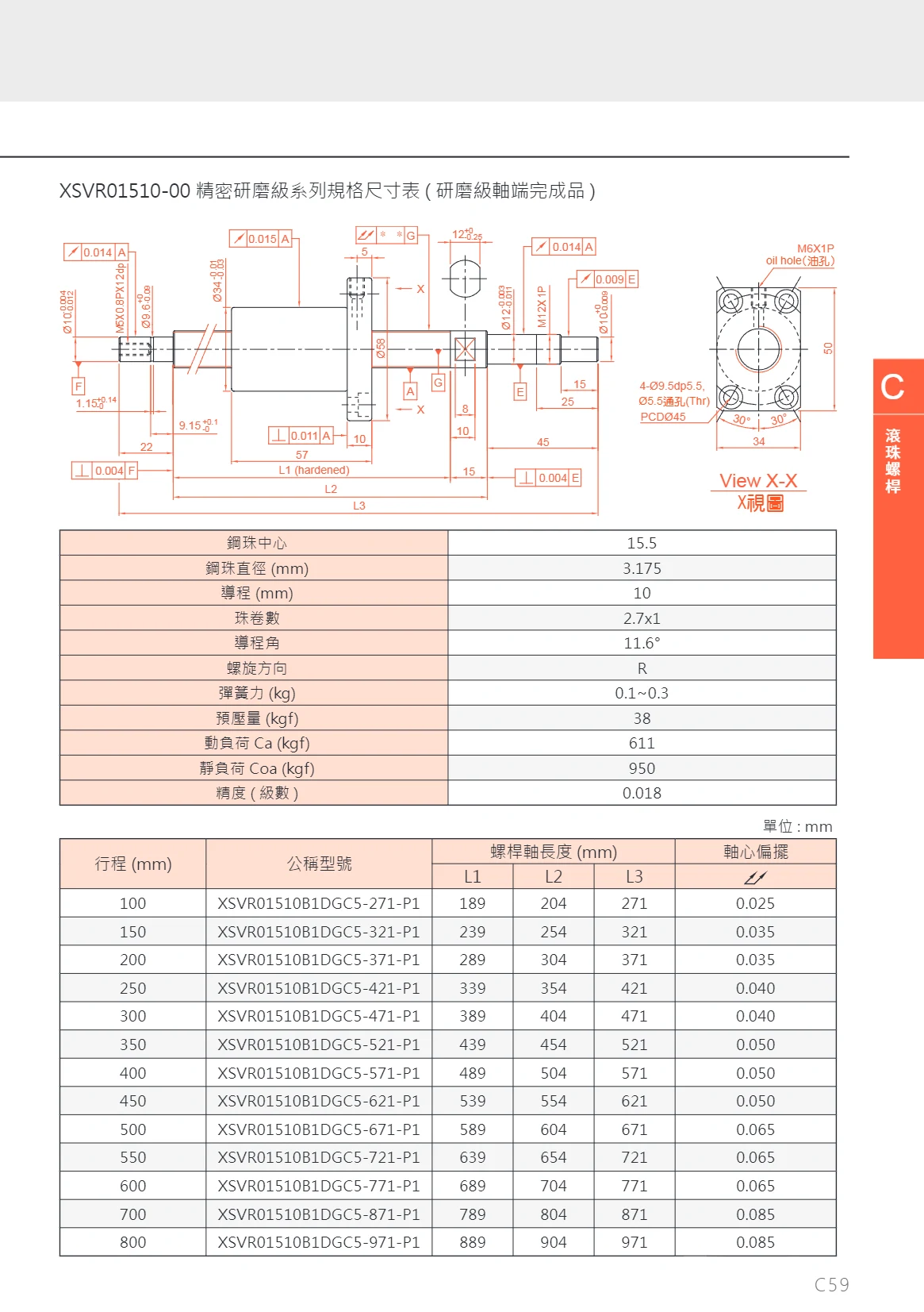
XSVR Precision Ground Ball Screw Series
This series features precision-ground ball screws manufactured using a grinding process, offering high accuracy, high rigidity, and low friction. A variety of stroke lengths are available, ranging from 100 to 800 mm. Model codes include designations for diameter, lead, preload class, and dust seals. These ball screws are suitable for high-precision positioning applications in semiconductors, machine tools, and automation equipment.
FGS Series Crossed-Roller Guide αβ Stages
The FGS series αβ stages are precision positioning stages with crossed-roller guides. Combining the X axis (α axis) and Y axis (β axis) provides linear motion in two degrees of freedom for precision alignment and fine adjustment in optical, inspection, semiconductor, and automation equipment. The crossed-roller guides offer high rigidity and low play, enabling micrometer-level positioning and smooth motion. Model designations consist of FGSX/FGSY (axis type), 60 (table size), travel (50/75mm), and L (mounting orientation/specification). The table size is 60mm, with travel options including 50mm and 75mm. The stages can be used individually or stacked to form a two-axis αβ platform.
FGFX/FGFY Series Manual Goniometer Stages
The FGFX/FGFY series consists of manual goniometer stages driven by a micrometer head. With a 40mm×40mm platform, they are suitable for precise angular adjustment of optical components, sensors, and small parts. FGFX has a single α axis with a travel of ±7° (center height 40mm) or ±6° (center height 60mm). FGFY has two axes, α and β, with ±7° travel on the upper α axis and ±6° on the lower β axis, and a center height of 40±0.4mm. The stages have a platform thickness of 20mm or 40mm, a load capacity of 28.4N (3kgf), and a weight of approximately 0.13kg. They feature a compact design, high adjustment resolution, and stable locking.
FGFX/FGFY Series Linear Modules
The FGFX/FGFY series consists of matched linear modules (single-axis actuators): FGFX serves as the X-axis and FGFY as the Y-axis. Together, they can form an XY Cartesian motion unit. The catalog provides outline and mounting dimensions for each size in dimensional drawings. Models are classified by frame size (40 or 60) and the second size designation (40/60 for frame size 40, 50/75 for frame size 60). The fixed L suffix denotes a structural variant of that model, such as a left/right or long configuration. Select the frame size according to load, stroke, and installation space, and refer to the dimensional drawings to confirm mounting hole locations and interface dimensions.
FGFX/FGFY Series Manual Goniometer Stages
FGFX/FGFY series manual goniometer stages use micrometer heads for precise angular adjustment of the stage surface. They are suitable for angular alignment and fine adjustment of optical components, sensor probes, fixtures, and other equipment. All stages have a 60mm×60mm platform, with center heights of 50mm or 75mm (tolerance ±0.2~±0.4mm) and platform thicknesses of 25mm (single-axis) or 50mm (stacked dual-axis). FGFX models are single-axis goniometer stages with motion about the α axis, offering a travel range of ±6° (50mm center height) or ±4° (75mm center height). FGFY models are dual-axis αβ goniometer stages, with ±6° travel on the upper α axis and ±4° on the lower β axis, allowing combined pitch and yaw adjustment. All models have a rated load of 49N (5kgf). Single-axis models weigh approximately 0.29kg and dual-axis models approximately 0.58kg. Their compact, rigid construction makes them suitable for benchtop precision adjustment.
FLY Series Crossed-Roller Guide X-XY Stages
FLY series X-XY stages use crossed-roller guides for smooth, high-precision movement. Their lightweight aluminum alloy bodies make them suitable for integration into other equipment. Table sizes range from 30mm to 200mm, with a variety of configurations available. Drive options include micrometer heads and precision screws. Movement is available in one direction along the X axis or in two directions along the XY axes. Standard models combine 2 X-axis stages, while thin and ultra-thin models have an integrated construction. For the configuration code, no mark indicates the standard type and M indicates the thin type. For the stage material, no mark indicates aluminum alloy and S indicates iron. For slide thickness, no mark indicates standard thickness, while a number indicates a non-standard thickness. Build the model code according to table size, mounting position, configuration, material, and thickness.
Manual Linear Translation Stages
Manual linear translation stages (also known as manual positioning stages or manual linear slide stages) use a micrometer head or precision screw to drive the platform for precise linear movement and positioning. They are suited to optics, inspection, semiconductor, laboratory, and other applications requiring fine manual adjustment. The platform moves back and forth between two end positions. To install, first move the platform to one end to expose the mounting holes, then insert the supplied bolts to secure it temporarily. Turn the micrometer head counterclockwise to move the platform to the opposite end, install and tighten the bolts on that side, and finally tighten the bolts on the first side, ensuring proper alignment with the mounting position. The stage can be configured with a digital micrometer (-D) for digital readout or a precision screw drive (-W). Common specifications include travel, platform size, positioning accuracy, drive type, and readout type.
FLX/FLY Series Manual Translation Stages
FLX/FLY series manual translation stages feature a black anodized aluminum alloy body and a micrometer head drive. They are suitable for optical, inspection and precision positioning applications. Table sizes are 80×80, 125×125, 160×160 and 200×200 mm, with travel of ±12.5mm for the 80 and 125 models and ±25mm for the 160 and 200 models. Load capacity is 98N (10kgf) or 392N (40kgf). The minimum scale division is 0.01mm, and travel parallelism is ≤0.02mm/25mm or ≤0.05mm/50mm. FLX stages move along the X axis, while FLY stages move along both the X and Y axes. The C/L/R/LM/RM suffixes indicate table position or configuration. Single-axis stages are 20~30mm thick, and two-axis stages are 40~56mm thick.
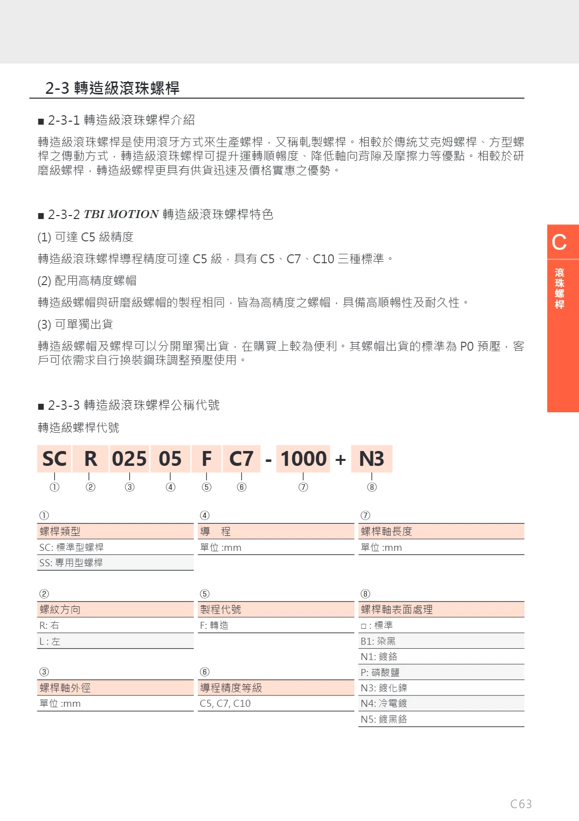
SS Series Ball Screws
TBI MOTION rolled ball screws (SS Series) are manufactured by thread rolling. Compared with conventional Acme and square-thread screws, they offer smoother operation, low axial backlash, and low friction. Compared with ground ball screws, rolled ball screws are available more quickly and at a lower cost. This series offers lead accuracy up to C5 and comes in three standard accuracy grades: C5, C7, and C10. The nuts are manufactured using the same process as ground-grade nuts, providing smooth operation and durability. Screws and nuts can be supplied separately. The standard nut preload is PO; users can change the ball size themselves to adjust the preload as needed. The part-number code includes parameters such as screw type (SS), thread direction, outer diameter, lead, process code, accuracy grade, shaft length, and surface treatment (standard, black oxide, chrome plating, phosphating, electroless nickel plating, cold plating, or black chrome plating).
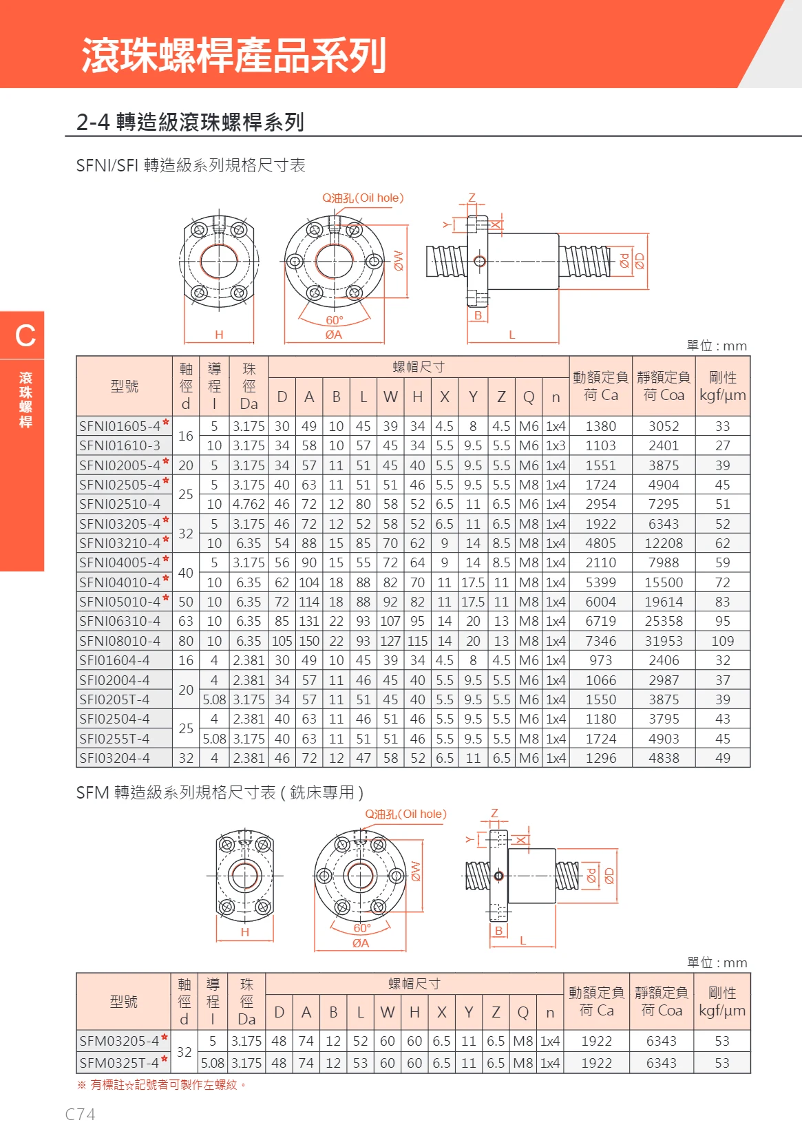
SFNI/SFI Rolled Ball Screw Series
The SFNI/SFI series consists of rolled ball screws with shaft diameters of 16–80 mm, leads of 4–10 mm, and ball diameters of 2.381–3.175 mm. Manufactured using a rolling process, these screws offer high precision and rigidity. They are suitable for general industrial automation equipment, dedicated milling machines, and other applications. Dynamic load ratings range from 1,380 to 1,922 kgf, static load ratings from 2,401 to 6,343 kgf, and rigidity from 27 to 53 kgf/μm. A variety of sizes are available; some models can be made with left-hand threads (marked with *).
FLX/FLY Series Linear Modules
The FLX/FLY series comprises linear modules and slides used in factory automation equipment. This page provides dimensional drawings for the series' size 200 models. Models shown include FLX200-L, FLX200-R, FLY200-LM, and FLY200-RM. The number 200 denotes the frame size, while L, R, LM, and RM distinguish the left- or right-hand mounting orientation and structural configuration. The catalog page does not provide detailed specifications such as rated load, stroke, or repeatability. When selecting a model, check its overall dimensions and mounting interfaces.
FLZ Series Crossed-Roller Guide Z-Axis Horizontal Lift Stages
The FLZ series consists of manual Z-axis horizontal lift stages with crossed-roller guides. The guide structure provides smooth, high-precision linear motion and stable repeat positioning, making these stages suitable for fine adjustment and positioning. The aluminum alloy body is lightweight and rigid, making it easy to integrate into other devices or equipment. Platform sizes range from 40mm~125mm, with a variety of specifications to suit different loads and installation spaces. A micrometer head provides micrometer-level feed and locking. Model numbers combine the movement method, movement direction, platform size, guide type, and stage thickness. Guides are available in single-rail and dual-rail configurations (the latter identified by 2 in the model number). Stage thickness is available in standard and nonstandard versions (nonstandard thickness is indicated by a number in the model number, in mm). These stages are suitable for optical, inspection, semiconductor, and automated assembly workstations requiring fine Z-axis horizontal lift adjustment. They are mounted with the crossed-roller guides oriented in parallel.
FLZ Series Precision Linear Stages
The FLZ series precision linear stages are differentiated by platform size codes in the catalog. Listed models include FLZ-40, FLZ-60, FLZ60-2, FLZ80-2, FLZ90-2, and FLZ90-2-H35. The codes 40, 60, 80, and 90 correspond to platform sizes of 40 mm, 60 mm, 80 mm, and 90 mm, respectively (refer to the dimensions shown in the outline drawings). The suffix -2 denotes a dual-position/dual-axis configuration, while -H35 denotes a special variant with a different platform height or mounting hole position. These stages combine an aluminum alloy body with a precision guide mechanism for short-travel linear positioning and fine adjustment. They are commonly used at precision adjustment stations in optical, inspection, semiconductor, and general automation equipment. To select a model, first choose the base model by the required platform size, then select the suffix according to the axis configuration and mounting height. Refer to the outline drawings and corresponding specification tables for travel, load, straightness, and other detailed specifications.
FLZ Series Manual Z-Axis Translation Stages
FLZ series manual Z-axis translation stages feature a black anodized aluminum alloy body and a micrometer head drive. They are suitable for optics, precision measurement, laboratory setup, and other applications requiring fine Z-axis adjustment. Platform sizes include 60mm×60mm, 80mm×80mm, 90mm×90mm, and 125mm×125mm. Standard travel is 10mm, while the FLZ125-2 offers 20mm. The minimum scale division is 0.01mm, parallelism is 0.05~0.1mm, load capacity is 58.8N(6kgf)~147N(15kgf), and weight is 0.39~1.98kg. The series includes low-profile or slim variants such as H35, H45, and N to meet different installation space and height requirements.
FLV Series Manual Positioning Stages
FLV Series manual positioning stages use crossed roller guides for smooth, high-precision linear motion. Their lightweight aluminum alloy construction makes them suitable for integration into other equipment. Driven by a micrometer head, they provide single-axis Z travel (vertical movement) and feature a parallel crossed-roller guide structure. Platform sizes range from 40mm to 125mm, with a variety of configurations to suit different installation spaces. The model code consists of the FLV series designation, platform size, and micrometer head mounting position. Mounting position options include C2, L, R, L2, and R2, allowing selection based on the assembly orientation. These stages are widely used for optical alignment, precision positioning, and experimental setups.
FLV Series Manual Vertical Stages
The FLV series comprises manual positioning stages that provide vertical motion along the Z axis. They feature a black-anodized aluminum alloy body and a micrometer head drive for precise height adjustment in optical, inspection, laboratory, and automation equipment. Table sizes range from 40×40mm to 90×90mm, with ±6.5mm travel and a minimum graduation of 0.01mm across all models. Load capacity ranges from 19.6N(2kgf) to 39.2N(4kgf), straightness is ≤0.01mm/13mm or ≤0.02mm/25mm depending on the specification, and weight ranges from 0.22~0.88kg. Models with the C2 suffix are available in various table sizes; select according to table size, load, and straightness requirements.
FLV Series Crossed-Roller Guide Vertical Stages
The FLV series consists of manual vertical stages (Z-axis) with crossed-roller guides and micrometer-head drives for fine vertical adjustment while maintaining a parallel platform. Platform widths are available in 40, 50, 60, 80, and 90 mm. These stages can be combined with FLX series horizontal stages (X-axis) to form FLEV series XZ two-axis stages. For example, the FLEV40-L-C2 combines an FLX40-L with an FLV40-C2. Micrometer heads can be mounted on the left (L), right (R), or center (C). The standard configuration has the model suffix -C2. Multi-axis combinations can be specified with suffixes such as -L-C2, -R-C2, -C-C2, -L-L2, -R-L2, and -C-L2, where “L2”, “R2”, and “C2” denote different Z-axis micrometer-head positions. These products are suitable for precision vertical positioning in optical, inspection, semiconductor, and automation equipment.
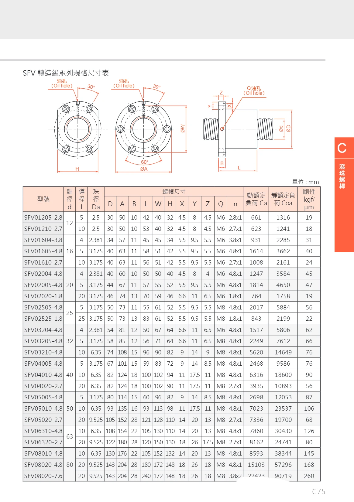
SFV Series Ball Screws
The SFV series features internally circulating ball screw and nut assemblies designed for precision transmission and positioning. Shaft diameters range from 12 to 80 mm, leads from 4 to 20 mm, and ball diameters from 2.381 to 9.525 mm. A variety of specifications are available to meet different load and rigidity requirements. Dynamic load ratings range from 661 to 72,423 kgf, static load ratings from 1,316 to 90,719 kgf, and rigidity from 19 to 260 kgf/μm. A range of nut sizes supports different mounting methods.
FRS Series Rotation Stages
FARAY FRS Series rotation stages (θ-axis) provide precise angular adjustment. The stage can first be rotated to an approximate position, secured using the coarse/fine adjustment switching screw, and then finely adjusted with the micrometer head. The series offers standard and precision accuracy grades, with a wide range of table sizes from Φ38mm to Φ160mm. Micrometer head positions include L and R, and the stage is available in standard or non-standard thicknesses. Model numbers specify the movement method, rotation direction/stage type, accuracy, table size, micrometer head position, and stage thickness. These stages are suitable for angular positioning and fine adjustment in optical, inspection, semiconductor, and automation equipment.
FRSP Series Manual Rotary Stages
The FRSP series comprises manual precision rotary stages (θ-axis) mounted through countersunk holes in the base. Loosen the coarse/fine adjustment selector screw to rotate the stage manually through 360° for coarse adjustment. Tighten the selector screw to make fine adjustments using the micrometer head. Before fine adjustment, make sure the locking screw is loose; once the desired position is reached, tighten the locking screw to secure the stage. Platform sizes range from Φ40~Φ125mm, with common models including FRSP40, FRSP60, FRSP80, FRSP85, FRSP90, FRSP110, and FRSP125. The θ-axis provides 360° coarse rotation + ±5° fine adjustment, with a minimum scale division of 0.01mm. These stages can serve as the θ-axis in an XYθ multi-axis assembly when combined with FLY/FLS series XY translation stages. Standard and precision (P) grades are available for optical, inspection, and precision positioning applications.
FRS Series Manual Rotation Stages
The FRS series comprises manual rotation stages (θ-axis angular positioning stages) driven by a micrometer head for rotational positioning along one θ axis. The aluminum alloy platform has a black anodized finish and is available in three diameters: Φ60mm, Φ90mm, and Φ125mm. Platform thickness is 15mm for Φ60 and 20mm for Φ90/Φ125. Travel consists of 360° coarse adjustment plus ±5° fine adjustment, making the stages suitable for inspection, optical alignment, precision assembly, and other applications requiring fine angular adjustment. The minimum scale graduation is 10′ for FRS60-L and 5′ for FRS90-L/FRS125-L, with micrometer head graduations of approximately 0.96′, 0.6′, and 0.46′, respectively. Rated load is 29.4N (3kgf), concentricity is 0.03mm, parallelism is 0.03~0.05mm, and weight is 0.16~0.90kg. Compact and offering high adjustment resolution, the stages can be combined with other manual positioning stages for adjustment along multiple degrees of freedom.
FRSP-L Series Manual Rotation Stages
FRSP-L series manual rotation stages (manual angular positioning stages) use a micrometer head for single-axis angular adjustment around the θ axis, with 360° coarse travel and ±5° fine travel. The body is made of black anodized aluminum alloy, with a 25mm platform thickness and diameters ranging from Φ38 to Φ160mm. The minimum scale division is 5°, and each micrometer division corresponds to 0.46′–1.44′. Concentricity is 0.03mm, parallelism is 0.03–0.05mm, load capacity is 9.8–49N, and weight is 0.10–1.20kg. The stage includes a locking screw and a screw for switching between coarse and fine adjustment. To take a reading, first read the disc scale (1° per division), then add the aligned vernier scale value on the body for a resolution of 0.1°. These stages are suitable for precise angular positioning and fine adjustment of optical components, sensors, samples, tooling and fixtures.
FRSP Series Precision Manual Rotation Stages
FRSP series precision manual rotation stages are designed for angular adjustment and precision rotational positioning in equipment. The model numbers correspond to sizes 40, 60, 80, 90, 100, and 125, and all models have the -L suffix. Each stage has a locking screw and a coarse/fine adjustment switching screw. Switching modes enables quick coarse adjustment, while locking the stage allows small angular corrections using the fine adjustment mechanism. The dimensional drawings show the mounting hole locations and thread specifications (such as M3 and M4) for the locking and coarse/fine adjustment switching screws in each size, facilitating connection to bases, adapter plates, or brackets. The series is suitable for workstations requiring manual fine adjustment and stable angular positioning.
FRSP/FRSPT Series Manual Rotation Stages
FRSP/FRSPT series manual rotation stages feature a black anodized aluminum alloy body and a micrometer drive, providing 360° coarse adjustment and ±5° fine adjustment. Table diameters range from Φ85mm to Φ158mm, with table thicknesses of 20~30mm and load capacities of 39.6~78.4N (4~8kgf). Minimum scale graduations are available in 5′ and 1° options, with each micrometer division corresponding to 0.36′~0.72′. Concentricity is 0.03mm and parallelism is 0.04~0.05mm. Suitable for manual angular adjustment in optics, inspection, precision positioning, and other applications.
LG Series Steel Rod and Ball Manual Translation Stages
LG Series steel rod and ball manual translation stages use precision linear steel balls and finely ground steel rods in the guideway structure. They offer low rolling friction, smooth motion, high precision and low cost, making them suitable for light-load positioning and fine adjustment. The main body is made of aluminum alloy, providing a lightweight, compact design that is easy to integrate into other devices or equipment. Two motion configurations are available: single-axis X feed and two-axis XY feed. The standard platform size is 60 mm, with custom sizes available on request. A micrometer head drives the feed and can be mounted in three positions: C (micrometer heads arranged symmetrically), L (left-side mounting) and R (right-side mounting), allowing selection based on operating space and reading direction. Stages are available in standard thickness (unmarked in the model number) or non-standard thickness (indicated by a number in mm) to suit different installation heights and travel clearances. When selecting a model, confirm the movement method, direction of travel, platform size, micrometer head mounting position and stage thickness in that order.
FLGX Series Manual Positioning Stages
FLGX series manual positioning stages (manual translation stages) feature a 40mm×40mm platform for precise manual positioning and fine adjustment of optical components, probes, and small workpieces. Travel is ±6.5mm, minimum scale graduation is 0.01mm, travel parallelism is ≤0.02mm/6mm, parallelism is 0.03~0.06mm, and load capacity is 19.6N(2kgf). The stages are available in an X-axis single-direction version (20mm platform thickness, approximately 0.13kg) and a Y-axis bidirectional version (40mm platform thickness, approximately 0.26kg). Three knob (lead screw) positions, C, L, and R, are available for the same platform size, making it easy to stack stages for multi-axis configurations and install them in confined spaces.
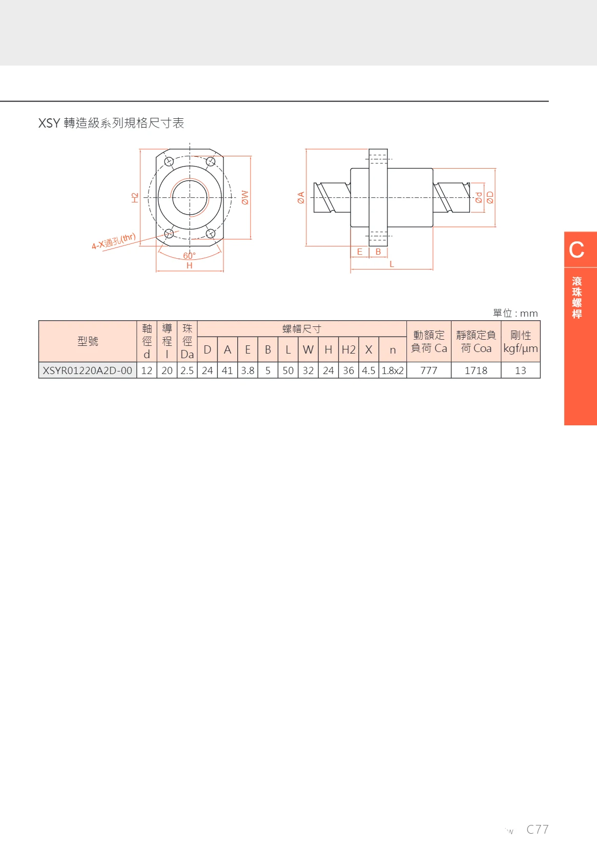
XSY Rolled-Grade Series
The XSY rolled ball screw series is manufactured using a rolling process, offering high precision, high rigidity, and excellent durability. This series is suitable for industrial drive applications such as automation equipment, CNC machine tools, and precision positioning systems. A variety of shaft diameter and lead combinations are available to meet different load and speed requirements. For example, model XSYR01220A2D-00 has a shaft diameter of 12 mm, a lead of 20 mm, a ball diameter of 2.5 mm, a dynamic load rating of 777, a static load rating of 1718, and a rigidity of 13 kgf/μm. Nut dimensions include parameters such as D, A, E, B, L, W, H, H2, X, and n, and can be selected to suit your requirements.
F LB Series Linear Ball Manual Translation Stages
F LB Series linear ball manual translation stages feature an integrated design with guideways machined directly into both the upper and lower plates, reducing machining and assembly errors. Gothic-arch grooves provide four-point contact between the balls and raceways at 45 degrees for precise, smooth motion. The body is made of SUS440C stainless steel with an electroless nickel-plated surface for strong corrosion resistance. Available in a variety of configurations with table sizes from 25~100mm, the stages can be selected by combining the movement direction (X, Y, V, EV, DV), table size, and micrometer head mounting position. They are suitable for manual precision positioning in optics, inspection, semiconductor, and factory automation applications.