Linear Motion Accessories — Page 9
FLBX/FLBY Series Manual Translation Stages
The FLBX/FLBY series manual translation stages feature SUS440C stainless steel bodies and micrometer-head drives for short-travel manual positioning in optical, precision measurement, semiconductor and laboratory applications. FLBX models provide single-axis X movement, while FLBY models provide two-axis XY movement. Platform sizes include 25×25, 40×40, 80×80 and 100×100mm, with travel ranges of approximately ±3, ±6.5 and ±12.5mm. The minimum scale division is 0.01mm, and load capacities range from 39.2N to 343N. Travel parallelism and parallelism are controlled to specification-dependent grades. The stages are compact, rigid and can be combined for mounting.
FLBX/FLBY Series Automation Components
This page presents the FLBX/FLBY series in a model list and dimensional drawings, covering six models: FLBX25-C, FLBY25-C, FLBX25-L, FLBY25-L, FLBX25-R, and FLBY25-R. Each model number consists of the FLBX or FLBY series designation, size 25, and a C/L/R variant suffix. Models can be selected based on their external dimensions. C/L/R may indicate different configurations or mounting styles; the specific differences should be confirmed using the dimensions and profiles in the drawings. This page does not provide technical specifications such as material, accuracy, load, or travel. Consult the complete catalog or contact the manufacturer when selecting a model.
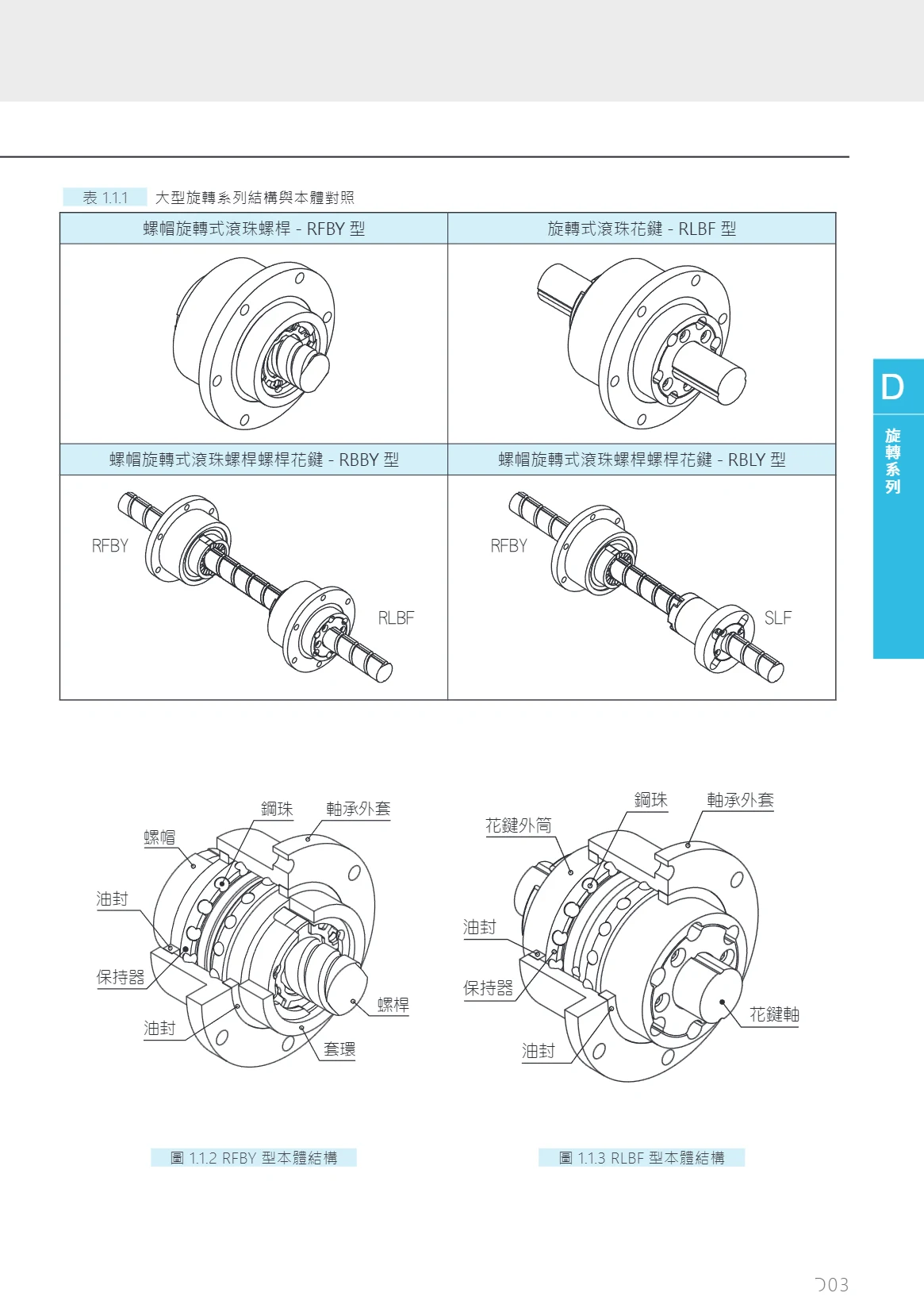
RFBY Rotating-Nut Ball Screw
The RFBY series comprises rotating-nut ball screws in the large rotary product range. The nut rotates while the screw shaft moves linearly, making the series suitable for long- or short-table mounting configurations. Accuracy grades are based on JIS B 1192-1997 and include rolled C7 and C10, as well as ground C7, C5, and C3. Shaft diameters range from 16 mm to 50 mm, with models from RFBY01616 to RFBY05050. Featuring a ball nut design, the series offers high rigidity and load capacity. It is commonly used in automation equipment, machine tools, and other applications requiring precise linear motion.
FLBX Series
The FLBX series, including the related FLBY models, is presented in this catalog as full-page dimensional drawings for checking the body outline and mounting interfaces. Each model designation consists of a body code and an orientation code: FLBX100 and FLBY100 identify size 100 bodies for the X and Y directions, respectively, while the suffixes -C / -L / -R indicate center, left, and right mounting orientations (configurations), respectively. When selecting a model, first choose FLBX or FLBY according to the equipment's axis layout, then select the C / L / R orientation based on available mounting space and potential interference. This series page provides dimensional drawings only; refer to the relevant drawing for specific dimensions, mounting hole locations, materials, and accuracy specifications.
FLBY Series Linear Modules
This page provides only an outline dimension drawing and three model designations for the FLBY series: FLBY100-C, FLBY100-L, and FLBY100-R. These are variants of the same size, distinguished by C/L/R. The source does not specify technical parameters such as travel, accuracy, material, load capacity, or mounting dimensions, nor does it provide model coding rules. The specific structural differences between C/L/R are not explained. When selecting a model, consult the outline dimension drawing to verify mounting interfaces, overall shape, and differences between variants, and confirm detailed specifications separately.
FLBV Series Manual Z-Axis Translation Stages
The FLBV series consists of manual, single-axis Z translation stages with a platform design, suitable for optical alignment, inspection, fine adjustment, and positioning small loads. Four platform sizes are available: 25mm×25mm, 40mm×40mm, 60mm×60mm, and 80mm×80mm, with corresponding travel ranges of ±3mm, ±6.5mm, ±6.5mm, and ±3mm. Load capacity is 9.8N(1kgf) or 49N(5kgf), and the minimum scale graduation is 0.01mm for all models. Motion perpendicularity is ≤0.01mm/6mm, ≤0.01mm/13mm, ≤0.01mm/13mm, and ≤0.02mm/25mm, respectively. Weight ranges from 0.09~1.20kg.
FLBV Series
This page provides dimensional drawings for four FLBV Series models: FLBV25-C2, FLBV40-C2, FLBV60-C2, and FLBV80-C2. This catalog page is intended only for checking overall and mounting dimensions; it does not provide detailed specifications such as material, accuracy, stroke, load, or interfaces. The number in each model designation indicates the size, while the C2 suffix identifies a configuration or variant within the series. When selecting a model, check the available installation space against the corresponding dimensional drawing and confirm performance specifications in the complete catalog or manufacturer's documentation. Suitable for factory automation equipment and mechanical structures that require layout based on dimensional drawings.
FLBEV Series Manual XZ-Axis Translation Stages
The FLBEV series consists of manual XZ translation stages that move along both the X and Z axes, providing manual positioning and fine adjustment for optical, inspection, and precision adjustment applications. Four platform sizes are available: 25mm×25mm, 40mm×40mm, 60mm×60mm, and 80mm×80mm, with corresponding travel ranges of ±3mm, ±6.5mm, ±6.5mm, and ±12.5mm. All have a minimum scale graduation of 0.01mm for precise manual feed adjustment. The 25 size has a load capacity of 9.8N (1kgf), while the 40, 60, and 80 sizes have a load capacity of 49N (5kgf). Weights increase with size, at 0.16kg, 0.55kg, 0.98kg, and 2.10kg respectively. The stages are compact and rigid. Model numbers combine the platform size, direction of movement, and configuration code, as in FLBEV25-L-C2 and FLBEV80-L-C2. Select a model based on available mounting space and load requirements.
FLBEV Series
This page provides dimensional drawings for the FLBEV series, including models FLBEV25-L-C2, FLBEV40-L-C2, FLBEV60-L-C2, and FLBEV80-L-C2. It does not provide specific technical details such as material, travel, accuracy, load capacity, or mounting method. When selecting a model, consult the dimensional drawing for the relevant size to confirm mounting interfaces and space requirements. This entry lists only models explicitly identified in the source and makes no assumptions about unspecified performance parameters.
FLBDV Series Manual Translation Stages
The FLBDV series consists of manual XYZ three-axis translation stages for precision positioning in optical, inspection, laboratory, and small-scale automation applications. Table sizes include 25×25, 40×40, 60×60, and 80×80 mm, with travel ranges of ±3 mm, ±6.5 mm, and ±12.5 mm; the minimum scale division is 0.01 mm. Load capacities are 9.8 N (1 kgf) and 49 N (5 kgf), and stage weights range from 0.23 to 3.00 kg. Models FLBDV25-L-C2, FLBDV40-L-C2, FLBDV60-L-C2, and FLBDV80-L-C2 meet multi-axis fine adjustment needs from compact, light-load applications to those requiring larger tables. They can be used for laboratory optical path adjustment, sample positioning, sensor mounting, and fine positioning of tooling and fixtures.
FLBDV Series Linear Modules
The FLBDV series comprises linear motion modules (linear stages) for factory automation. The catalog provides dimensional drawings for four sizes: FLBDV25-L-C2, FLBDV40-L-C2, FLBDV60-L-C2, and FLBDV80-L-C2. In the model designation, FLBDV is the series code, 25/40/60/80 indicate four cross-sectional sizes in ascending order, and the suffix -L-C2 identifies the length/configuration designation. When selecting a model, check the mounting hole locations, overall profile, and mounting surface height against the dimensional drawing for the relevant size to ensure compatibility with the machine base and load attachment. This page provides dimensional information only. For performance specifications such as stroke, accuracy grade, allowable load, and maximum speed, consult the other technical pages for this series or contact the manufacturer.
FLE Series XZ-Axis Combination Stages
The FLE series XZ-axis combination stages are manual multi-axis positioning stages with a black anodized aluminum alloy body, crossed-roller guides, and micrometer-head drives for horizontal X-axis and vertical Z-axis adjustment. Platform sizes range from 40×40mm to 125×125mm, with X-axis travel of ±6.5mm or ±12.5mm, Z-axis travel of 10mm or 20mm, a minimum graduation of 0.01mm, and load capacities from 19.2N to 147N. In the model code, E indicates XZ movement, the number indicates the platform size, and no Z-axis designation indicates a single guide rail while 2 indicates dual guide rails. These stages are suitable for precision manual positioning in optics, inspection, tooling, and fixtures.
FLX Series Manual X-Axis Translation Stages
The FLX series comprises X-axis modules in the FARAY manual translation stage range. They use parallel crossed-roller guides and a micrometer head drive, with travel of ±6.5mm (40 stage size) or ±12.5mm (60 and larger stage sizes) and a minimum scale division of 0.01mm. The main body is made of black-anodized aluminum alloy. The X-axis stage can be stacked with an FLZ series Z-axis stage (single or dual guide rail) to form an FLE series XZ-axis combination stage for horizontal and vertical motion. The combination stages have platform sizes from 40×40 to 125×125mm, Z-axis travel of 10mm/20mm, load capacities of 19.2N~147N, and weights of 0.31~3.38kg. They are suitable for optics, inspection, semiconductor, and other applications requiring precise manual adjustment in multiple directions. The combination model naming rule is: F (parallel crossed-roller guides with micrometer head drive) + E (XZ directions, horizontal and vertical motion) + platform size (mm) + L + Z-axis configuration (no marking for single guide rail, 2 for dual guide rails).
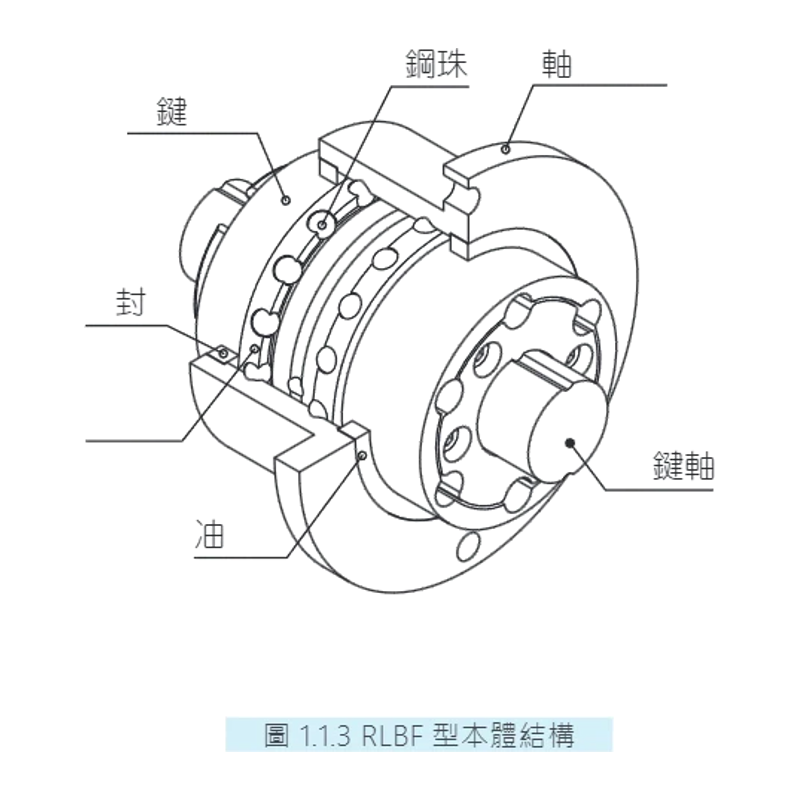
RLBF Series Ball Splines
The RLBF series consists of rotary ball splines designed for automation equipment requiring combined rotary and linear motion. Relative movement between the spline nut and spline shaft transmits torque and linear displacement, offering high rigidity and precision. Accuracy grades include Normal (N), High (H), and Precision (P). Accuracy specifications cover factors such as runout of the spline nut’s outer diameter relative to the spline shaft support section, squareness of the spline shaft end face, and concentricity of mounting sections. Specific values are provided according to nominal shaft diameters (16–50 mm) and length ranges. These products are widely used in robotic arms, assembly lines, machining centers, and similar applications.
FLZ Series Manual Z-Axis Elevation Stage
The FLZ series is the Z-axis (vertical elevation) module in FARAY's multi-axis stage system. It can be stacked with an FLX series X-axis stage to form an FLE series XZ-axis horizontal and vertical positioning stage. It features crossed-roller guides, a micrometer head drive, and a black anodized aluminum alloy body, with a minimum scale graduation of 0.01mm. Five sizes are available by platform size: 40, 60, 80, 90, and 125. Z-axis configurations include single-guide models (unmarked in the model number, such as FLZ-40 and FLZ-60) and dual-guide models (with the suffix 2, such as FLZ60-2, FLZ80-2, FLZ90-2, and FLZ125-2). The dual-guide design offers significantly greater load capacity. Z-axis travel is 10mm for the 40/60 sizes and 20mm for the 80/90/125 sizes. The corresponding combined stages have a load capacity of approximately 19.2N~147N and weigh 0.31kg~3.38kg. They are commonly used in optics, inspection, semiconductor applications, and other settings requiring precise manual height adjustment.
FLE Series Roller Linear Guides
The FLE series consists of heavy-duty roller linear guides that use rollers as rolling elements. They offer high rigidity, high load capacity, and impact resistance, making them suitable for linear guidance in machine tools, automated production lines, and heavy-load handling equipment. The catalog provides dimensional drawings for nominal sizes 40, 60, 80, 90, and 125. The model suffix L denotes an extended block, while -2 denotes a two-block or double-row configuration. Select according to the available mounting space, load, travel, and accuracy grade.
FLEV Series Multi-Axis Combination Stages
The FLEV series multi-axis combination stage is a manual XZ two-axis stage with vertical lift. It uses parallel crossed-roller guides and micrometer drives for precision positioning. Four platform sizes are available: 40, 50, 60, and 90 mm. The X- and Z-axis micrometer heads can be mounted in left (L), right (R), center (C), and C2/L2/R2 combinations to suit different operating spaces. Combining an FLX series X-axis stage with an FLV series Z-axis stage, it is suitable for precision adjustment in automated optics, inspection, semiconductor, and other applications.
FLX Series X-Axis Manual Translation Stages
The FLX series comprises X-axis manual translation stage units for FARAY multi-axis assemblies. They are commonly combined with FLV series Z-axis units to form XZ-axis multi-axis stages with vertical lift, including models FLEV40-L-C2, FLEV50-L-C2, FLEV60-L-C2, and FLEV90-L-C2. The stages are driven by micrometer heads and use crossed-roller guides for parallel motion. Platform sizes include 40 mm, 50 mm, 60 mm, and 90 mm. The model suffix L indicates the X-axis micrometer head mounting position. They are suitable for factory automation, optical alignment, and inspection equipment requiring precise manual positioning.
FLEV Series Manual XZ Translation Stages
FLEV series manual XZ translation stages feature a black-anodized aluminum alloy body and micrometer-head drive for precise manual positioning and fine adjustment along the X and Z axes. Four platform sizes are available: 40mm×40mm, 50mm×50mm, 60mm×60mm, and 90mm×90mm. X-axis travel ranges from ±6.5mm to ±12.5mm, while Z-axis travel is ±6.5mm for all models. The minimum scale division of 0.01mm enables submillimeter fine adjustment. With rated loads of 19.2N–58.8N (2kgf–6kgf) and weights of 0.36kg–1.35kg, the stages balance rigidity and low weight. They are suitable for positioning and fine adjustment of optical components, probes, sensors, and miniature workpieces, and can be combined with single-axis stages to create multi-axis adjustment systems.
FLD Series Multi-Axis Combination Stages
The FLD series consists of manual XYZ three-axis combination stages with horizontal and vertical adjustment. They combine an FLY series X-axis stage with an FLZ series Z-axis stage to provide displacement adjustment in all three XYZ directions. They are suitable for precision alignment and fine adjustment in optical, inspection, semiconductor, and general automation equipment. Table sizes range from 40×40mm to 150×150mm. A micrometer head provides fine feed adjustment, while the lightweight construction keeps total weight between 0.44~4.78kg. Load capacity ranges from 19.2N(2kgf)~147N(15kgf). XY-axis configurations are available in standard (unmarked), thin M, and ultra-thin B versions. Z-axis options include single guide rail (unmarked) and dual guide rail 2, selected according to load and rigidity requirements.
FLY Series X-Axis Stages
The FLY series X-axis stages are FARAY manual positioning stages used primarily as the X-axis (horizontal) component of FLD series XYZ multi-axis assemblies, paired with FLZ series Z-axis stages. They are driven by micrometer heads and available with platform sizes of 40×40, 60×60, 80×80, 90×90, and 125×125 mm. In the model suffix, L indicates the micrometer head position and M indicates a low-profile design (models without M are standard). They are suitable for applications requiring precise manual positioning, including optical alignment, inspection equipment, and semiconductor manufacturing. Refer to the drawings for each model for specific travel, body material, minimum graduation, and standalone load capacity.
FLZ Series Z-Axis Translation Stage
The FLZ series Z-axis translation stage is the Z-axis component of FARAY multi-axis modular platforms (XYZ-axis horizontal and vertical assemblies). Paired with FLY series X-axis stages and FLD modular platforms, it forms multi-axis precision positioning systems with platform sizes of 40, 60, 80, 90, 125 and more. Micrometer heads drive the stages, with precise adjustment achieved through their positioning and configuration. The assembled platforms range from 40mm×40mm to 150mm×150mm, with load capacities from 2kgf to 15kgf and overall weights from 0.44kg to 4.78kg. Z-axis guides are available in single-guide (no model suffix) and dual-guide (model suffix 2) versions. Applications include optical adjustment, precision positioning, laboratory equipment and automated equipment.
FLD Series Linear Modules
The FLD series linear module catalog provides dimensional drawings for models including FLD40-LM, FLD60-LM, FLD80-LM-2, FLD90-LM-2, and FLD125-LM-2, covering frame sizes 40, 60, 80, 90, and 125. These modules are suitable for linear motion mechanisms in factory automation equipment, with sizes available to suit different space and load requirements. Detailed specifications such as lead, stroke, accuracy, and rated load are not listed on this page. When selecting a model, consult its dimensional drawing and additional technical documentation.
FLDV Series XYZ Multi-Axis Combination Stages
The FLDV series XYZ multi-axis combination stages use a parallel crossed-roller guide structure and are driven by micrometer heads for manual precision positioning along the X, Y and Z axes. The Z axis provides vertical movement. Table sizes are 40, 50, 60 and 90 mm. The XY axes use the FLY series, and the Z axis uses the FLV series. Configurations include standard (unmarked, M), slim (B) and ultra-slim types. Refer to the manufacturer's diagrams for the positions of the XY- and Z-axis micrometer heads. These stages are suitable for multi-axis positioning in optical alignment, precision inspection, laboratory setup and small-scale automation equipment.
RBBY Precision Ball Screw Spline
The RBBY series features a rotating-nut ball screw spline that combines the functions of a ball screw and a ball spline, enabling simultaneous rotary and linear motion. Axial clearance is 0 or less, with lead accuracy up to C5; rotational backlash is 0 or less (P1 light preload), and spline accuracy is H. Shaft diameters range from 16 to 50 mm, and leads from 16 to 50 mm. The number of ball circuits is 1.8 × 1 (A1), and the manufacturing process is grinding (G). Standard models include RBBY01616 and RBBY02020, among others. Screw spline shaft lengths can be customized to meet customer requirements. Suitable for automation equipment, machine tools, and other applications requiring precise combined rotary and linear motion.
FLY Series Manual XY Translation Stages
The FARAY FLY series comprises manual XY translation stages with crossed-roller guides and micrometer-head drives. The stages use parallel-direction crossed-roller guides and are suitable for precision positioning, optical alignment, and fine adjustment in laboratory applications. Four platform sizes are available: 40, 50, 60, and 90 mm, corresponding to models FLY40-LM, FLY50-LM, FLY60-LM, and FLY90-LM. For combined applications, these XY stages can be stacked with FLV series Z-axis stages (FLV40-C2, FLV50-C2, FLV60-C2, and FLV90-C2) to form FLDV series XYZ three-axis stages with vertical lift. Three configurations are available: standard M, slim B, and ultra-slim (unmarked). The micrometer-head mounting position can be selected according to the manufacturer's diagrams.
FLV Series Z-Axis Stages
The FLV series comprises FARAY manual Z-axis stages, also known as vertical translation stages. They use crossed-roller guides and micrometer drives, allowing an X-axis stage to be mounted vertically for use as a Z axis in multi-axis assemblies. The range includes high-precision integrated models and medium-precision split models, with platform sizes of 25, 40, 50, 60 and 90 mm. Made of anodized aluminum alloy, the stages are black as standard with no color designation; white versions require the suffix W. They are often combined with FLY series XY-axis stages to form FLDV series XYZ three-axis stages for precision positioning in optical, inspection, semiconductor and automation equipment.
FLDV Series Manual XYZ Translation Stages
FLDV series manual XYZ translation stages feature a black anodized aluminum alloy body and micrometer drives for precise positioning along the X, Y, and Z axes. Four platform sizes are available: 40×40, 50×50, 60×60, and 90×90 mm. They offer X-axis travel of ±6.5 to ±12.5 mm, Z-axis travel of ±6.5 mm, a minimum scale division of 0.01 mm, a rated load of 19.2 to 58.8 N (2 to 6 kgf), and a body weight of 0.49 to 1.83 kg. The platform has M3/M4 threaded holes and countersunk mounting holes for direct connection to optical components, fixtures, and inspection equipment. These stages are suitable for optical alignment, precision positioning, and laboratory and production line setup.
FLSP Series XYθ Multi-Axis Combination Stages
The FARAY FLSP series consists of manual XYθ multi-axis combination stages integrating X and Y linear motion with a θ rotation stage. They are suitable for precision alignment, optical adjustment, and multi-degree-of-freedom fine adjustment in automated equipment. Platform sizes include Φ38, Φ60, Φ80, Φ90, and 125 mm, with XY-axis travel options including ±6.5 mm and ±12.5 mm. The θ axis provides 360° coarse adjustment and ±5° fine adjustment. The stages feature crossed-roller guide structures and are available in standard, slim M, ultra-slim B, and precision P configurations, with L/R micrometer head positions. Load capacity is approximately 8.8–39.2 N and weight is 0.37–1.62 kg, depending on the model. Other configurations can be assembled to customer requirements.
FLY Series Single-Axis Positioning Stages
The FLY series from FARAY comprises manual precision positioning stages driven by micrometer heads for precise linear movement along a single axis. Available in a range of platform sizes (40, 60, 80, 90, 125mm, etc.), these stages can be combined with FRSP series θ-axis rotary stages to form XYθ multi-axis platforms (FLSP series). They are suitable for optical alignment, precision measurement, semiconductor equipment, and other applications requiring precision positioning with multiple degrees of freedom. Travel is up to ±12.5mm, the smallest scale division is 0.01mm, and load capacity ranges from 8.8N(1kgf) to 39.2N(4kgf).
FLSP Series Linear Modules
The FLSP series comprises linear modules (linear actuator units). This catalog page provides dimensional drawings showing the overall profiles and mounting interface dimensions for each size in the series. The series is available in four frame sizes: 40, 60, 80, and 90. Model numbers consist of FLSP, the size number, and a mounting configuration suffix. Suffixes such as L and LM indicate different mounting and drive configurations. Engineers can use the dimensional drawings to check mounting hole locations, body length, and interface positions when selecting a model and designing mating equipment. As this page contains dimensional drawings only, refer to other pages of the complete catalog for specifications such as effective stroke, lead, repeatability, rated load, and motor configuration.
FLSPK Series Manual Multi-Axis Positioning Stages
The FLSPK series manual multi-axis positioning stages feature a black-anodized aluminum alloy body and are directly driven by micrometer heads. They provide precise manual positioning along the X and Y linear axes and the θ rotational axis, making them suitable for multidimensional alignment of optical components, probes, samples, and more. Two table diameters are available: Φ100mm and Φ158mm, with XY travel of ±12.5mm and ±25mm, respectively. The θ axis offers 360° coarse adjustment and ±5° fine adjustment. Both models have a minimum scale division of 0.01mm and a rated load of 49N (5kgf), with overall weights of 1.39kg and 6.04kg, respectively. The series can be separated into modules and recombined as needed: the XY modules are FLY100-LBK / FLY160-LMK, and the θ modules are FRSPT100-L / FRSPT160-L, allowing users to assemble an XYθ stage to suit their needs.
FLY Series Manual Translation Stages
The FLY series manual translation stages are precision positioning platforms made of black-anodized aluminum alloy. Driven by micrometer heads with a minimum scale division of 0.01mm, they are suitable for precise positioning and fine adjustment of optical components, samples, and fixtures. This page covers two XYθ three-axis combined stages, FLSPK100-LB and FLSPK160-LM, with platform diameters of Φ100mm and Φ158mm and XY travel ranges of ±12.5mm and ±25mm, respectively. The θ axis provides 360° coarse adjustment and ±5° fine adjustment. Both have a rated load of 49N(5kgf) and weigh 1.39kg and 6.04kg, respectively. Each combined stage consists of an FLY series XY translation stage (FLY100-LBK or FLY160-LMK) and an FRSPT series θ rotary stage (FRSPT100-L or FRSPT160-L). They enable precision alignment across multiple degrees of freedom and are commonly used in inspection, assembly, and optical experiments.
FRSPT Series Manual Rotation Stages
The FRSPT series consists of manual rotation stages (θ-axis) used as rotary-axis modules in FLSPK combination stages. They can be combined with XY-axis stages such as the FLY100-LBK and FLY160-LMK to create the FLSPK100-LB and FLSPK160-LM multi-axis positioning stages, respectively. The series is suitable for manual angular adjustment in optics, precision measurement, and laboratory applications. The current catalog lists the FRSPT100-L and FRSPT160-L models, corresponding to the 100-size and 160-size combination stages, respectively. Check the relevant model page for specifications such as stage dimensions, travel, load capacity, and graduations.
RBLY Series Ball Screw Splines
The RBLY series consists of nut-rotating ball screw splines that combine the RFBY (nut-rotating ball screw) with the SLF (ball spline). It offers both the high-precision linear transmission of a ball screw and the rotary torque transmission of a ball spline. Axial clearance is 0 or less, and rotational backlash is 0 or less (light preload P1). The lead accuracy grade is C5, and the spline shaft accuracy grade is H. Standard models cover shaft diameters from 16 mm to 50 mm, with the lead matching the shaft diameter (16–50 mm). The shaft’s outside diameter, lead, length, preload grade, and number of thread starts can be customized according to the model coding system. Suitable for precision applications requiring compound motion, including automation equipment, machine tool spindles, and robots.
FLTP Series Multi-Axis Combination Stages
The FLTP series is a range of FARAY manual positioning stages that combine stacked XY, Z and θ axes (rotary stage) into a four-axis XYZθ configuration. Driven by micrometer heads, they provide micrometer-level manual positioning with a minimum scale division of 0.01mm. Table diameters range from Φ38~Φ125mm (40/60/80/90/125). XY travel is available in ±6.5mm and ±12.5mm ranges, Z travel is 10mm, and the θ axis provides 360° coarse adjustment and ±5° fine adjustment. Load capacity is 9.8~39.2N (1~4kgf), and total weight is 0.54~2.33kg. XY configurations include standard, thin (M) and ultra-thin (B) versions. The Z axis is available with a single guide rail or dual guide rails (2), and micrometer head positions include L and R orientations as shown in the diagrams. Applications include optical inspection, semiconductors, precision measurement and laboratory adjustment. In addition to standard configurations, other combinations can be customized to customer requirements.
FLTP Series Linear Modules
The FLTP series linear modules from FARAY AUTOMATION (Faray) feature an aluminum profile body with a timing belt or lead screw drive for linear positioning, handling, and sliding motion in automation equipment. This dimensional drawing page lists several models by module size: FLTP40, FLTP60, FLTP80, and FLTP90 correspond to four cross-section sizes, 40/60/80/90, covering applications from small, light-duty to medium-sized, medium-duty systems. Model suffixes distinguish designs and configurations: -LM denotes the basic linear module configuration, -L denotes an alternative design, and the final -2 indicates a configuration variant such as dual sliders or dual outputs. Select the appropriate size based on stroke, load, and installation space, and check the dimensional drawings for the specific stroke and mounting dimensions.
Dovetail Rack-and-Pinion Driven Linear Module
The dovetail rack-and-pinion driven linear module is part of the FARAY (FARAY AUTOMATION) linear motion product line. This series uses a dovetail groove (V-shaped sliding guide surfaces) for guidance and a meshing rack and pinion for linear drive. The rack is fixed to the guide base, while the pinion moves with the carriage. The design offers high structural rigidity, strong load capacity, and extendable travel through joined sections, making it suitable for long-travel, medium- to low-speed, heavy-load handling, positioning, and reciprocating transport applications. Clearance at the dovetail surfaces can be adjusted with a gib to balance guiding accuracy and wear resistance. The drive can be combined with a gearbox, servo motor, or handwheel. Key selection factors include guide size, travel, gear module, rack length, load, and mounting method. This page provides series-level information only; specific models and code combinations are not listed.
LW Series Dovetail Rack-and-Pinion Linear Modules
FARAY LW series dovetail linear modules use a rack-and-pinion drive and offer a high operating frequency, making them suitable for applications requiring fast movement and long travel. The lightweight aluminum alloy body makes them easy to integrate into other equipment. The product range includes standard and long-travel series. Standard models are available with 25×42 or 40×40 table sizes and a choice of single-direction X-axis, bidirectional X-axis, single-direction Z-axis, two-direction X-axis, or three-direction XYZ movement. They are available with a base plate (no designation) or without one (N). The long-travel series builds on the standard design with a specified rail length (in mm) and number of sliders (1 by default; multiple sliders can be specified numerically), enabling longer travel and multi-station loads. The modules use a parallel-motion dovetail design.
FLW Series Manual Translation Stages
FLW series manual translation stages feature a black anodized aluminum alloy body and a handwheel-driven rack-and-pinion mechanism. They are suitable for manual precision positioning in optical adjustment, inspection, laboratory and other applications. Four platform sizes are available: 25×42mm, 40×40mm, 40×60mm and 40×90mm. Travel ranges from ±10mm to ±30mm, load capacity from 24.5N(2.5kgf) to 49N(5kgf), minimum scale division is 0.1mm, travel parallelism ranges from ≤0.3mm/24mm to 0.3mm/60mm, and parallelism ranges from 0.03~0.08mm. Each platform size is available in five travel configurations: single-axis X, two-axis XY, single-axis Z, two-axis XZ and three-axis XYZ. Model numbers consist of FLW + direction code (X/Y/Z/E/D) + platform size code (2542/4040/4060/4090). Single-axis stages are 34mm thick, two-axis stages are 60~62mm thick, and weights range from 0.16~1.20kg.
FLW Series Linear Modules
The FLW series is identified by the FLW prefix in the catalog and includes X, E, Y, D, Z and other configurations, with size codes including 2542, 4040, 4060 and 4090. The page primarily provides dimensional drawings. Model numbers consist of FLW + a configuration letter + a four-digit size code. These modules are suitable for linear motion and positioning in automation equipment. As the page lists only model numbers and outline drawings, travel, rated load, mounting hole positions and motor configurations should be confirmed using the drawing or specification sheet for the relevant model.
FLWX Series Dovetail Rack-and-Pinion Driven Linear Stage
The FLWX series dovetail linear stage uses a rack-and-pinion drive for high-frequency operation, making it suitable for fast movement and long-travel applications. Its lightweight aluminum alloy body is easy to integrate into other equipment. The stage has a 40×40 mm platform and is available in lengths from L100 to L300, with travel from 60 to 260 mm, parallelism of 0.05 to 0.15 mm, and weight from 0.25 to 0.53 kg. The long-travel design can accommodate multiple carriages for linear positioning and conveying in automated equipment.

RFSY Rotating-Nut Ball Screw
The RFSY series features rotating-nut ball screws with an integrated design, offering high precision, high rigidity, and low noise. The model code comprises the nominal model, thread direction, screw shaft outer diameter, lead, preload code, nut type, seal code, accuracy grade, stroke, and accessories. These screws are suitable for precision positioning applications in automation equipment, machine tools, and other systems.
FLWZ Series Dovetail Rack-and-Pinion Linear Stages
FARAY FLWZ Series dovetail linear stages use a rack-and-pinion drive for high-frequency operation, making them suitable for applications requiring rapid movement and long travel. Made primarily of lightweight aluminum alloy, they are suitable for integration into other equipment. The long-travel design can accommodate multiple carriages to increase load capacity and the number of workstations. Models are designated in the form FLWZ40-L, with a stage size of 40 and five length options: L100, L150, L200, L250 and L300, with corresponding weights of 0.46~0.74kg. Overall dimensions L and L1 and the travel vary by length. Consult the dimensional drawing and select the appropriate model based on the available mounting space and required travel.
FLWGZ Series Manual Z-Axis Translation Stages
The FLWGZ series consists of manual single-axis Z translation stages. A handwheel drives a rack-and-pinion mechanism for micrometer-scale manual height adjustment, making them suitable for aligning and fine-tuning the height of small components such as optical elements, sensors, fixtures, and probes. The aluminum alloy body has a black anodized finish and is lightweight, rigid, and resistant to wear and corrosion. The flat, square platform has mounting holes and can be stacked directly with other X/Y-axis translation stages to form a multi-axis positioning system. Two models are available: FLWGZ40 and FLWGZ60, with platform sizes of 40mm×40mm and 60mm×60mm, travel ranges of 10mm and 20mm, platform thicknesses of 40-50mm and 50-70mm, load capacities of 9.8N (1kgf) and 14.7N (1.5kgf), and weights of 0.12kg and 0.40kg, respectively. Select a model based on the required platform size, travel, and load. Models with larger platforms and longer travel have correspondingly higher load capacities and weights.
LWF/RWF Series Dovetail Precision Screw-Driven Translation Stages
The LWF/RWF series is a range of low-profile manual translation stages driven by a precision screw, with 0.5mm of travel per knob revolution. Three platform sizes are available: 25×25mm, 40×40mm, and 60×60mm. The 25 and 40 platforms are 15mm thick, while the 60 platform is 17mm thick. Made entirely of aluminum alloy, the stages are lightweight and compact. Motion configurations include X (single X axis), Y (XY axes), V (single Z axis), EV (XZ axes), and DV (XYZ axes). The locking screw can be positioned on the left or right to suit installation requirements. These stages are suitable for optics, precision measurement, laboratories, and other applications requiring fine adjustment.
FLWF Series Manual Translation Stages
FLWF series manual translation stages feature a black anodized aluminum alloy body and a precision screw drive. Three table sizes are available: 25×25mm, 40×40mm, and 60×60mm, with corresponding travel ranges of ±5mm, ±7mm, and ±9mm. The minimum scale division is 0.1mm. Three configurations are available by axis of travel: single-axis X (FLWFX), two-axis XY (FLWFY), and single-axis Z (FLWFV), each in L and R versions. Table thickness is 15mm or 17mm for X-axis models and 30mm or 34mm for XY-axis models. Load capacity is 9.8~39.2N (1~4kgf), travel parallelism is ≤0.02mm/10mm, parallelism is 0.03~0.06mm, and weight is 0.03~0.38kg. These stages are suitable for fine positioning and alignment in optical adjustment, precision measurement, and small automated devices.
FLWF Series Linear Actuators
The FLWF series consists of slide-type linear actuators. The catalog provides outline dimension drawings showing the body profile and mounting dimensions of each model. The series is available in two frame sizes, 25 and 40, and five mounting types: X, Y, V, EV, and DV. Each type is available in L (left) and R (right) motor/cable exit orientations, providing a range of model combinations. To select a model, first choose the 25 or 40 frame size based on the load and effective travel requirements. Then select the mounting type and left or right orientation to suit the available installation space. Use the mounting hole positions, body length, and other dimensions in the corresponding outline drawing for mechanical design and interference checks. The catalog page provides only outline dimension drawings and does not list specific performance parameters such as rated load, travel, or accuracy.