product — Page 54
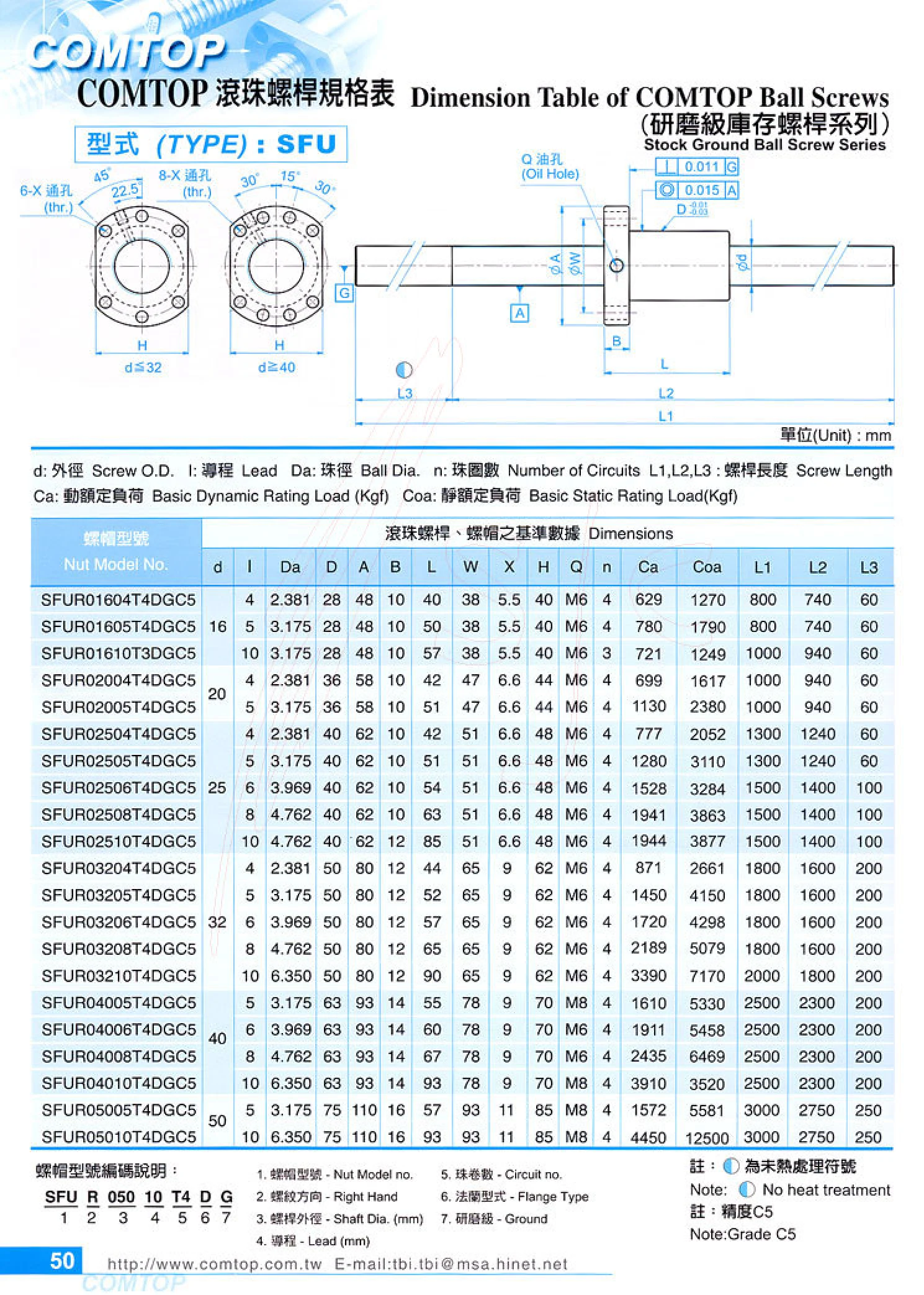
SFU Series Ball Screws
The SFU series is a standard external tube-return ball screw assembly consisting of a screw shaft, nut, steel balls, and return tubes. It converts rotary motion into linear motion, offering high transmission efficiency, low friction, and consistent positioning accuracy. Models are designated by nominal diameter and lead, with common nominal diameters ranging from 12~80 mm and leads from 2.5~20 mm. Overall screw length, thread length, and travel can be customized, with options for single or double nuts and various preload and accuracy grades. The nut flange has 6 or 8 through holes (thr.) for bolt mounting. End configurations and shaft-end machining can also be customized to customer drawings. These ball screws are widely used in CNC machine tools, engraving machines, injection molding machines, automated production lines, and various precision linear motion mechanisms.
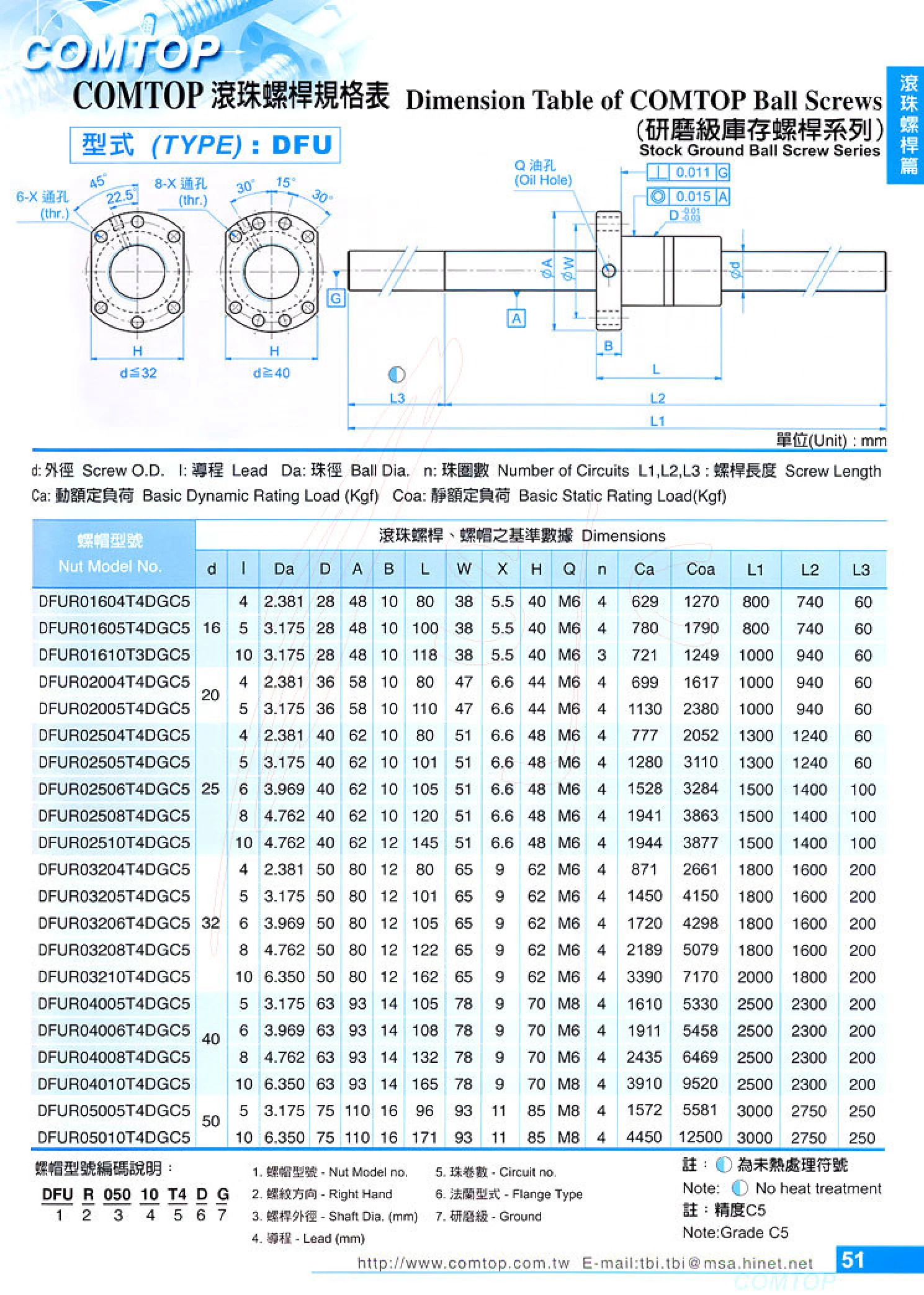
DFU Series Ball Screws
COMTOP DFU ball screws are standard, stocked precision-ground ball screws featuring flanged nuts. They consist of a precision-ground screw shaft and an internally recirculating flanged nut, converting rotary motion into high-precision linear motion. They are widely used in CNC machine tools, dedicated automation equipment, dispensing machines, screwdriving machines, inspection platforms, and other applications. The catalog organizes selection by nut model code: the nut model determines the nominal screw diameter, lead, and nut flange profile; the overall shaft length, end machining (per machining drawing), and accuracy grade are then specified as needed. Key selection parameters typically include nominal diameter, lead, nut flange dimensions, dynamic and static load ratings, axial rigidity, and positioning accuracy. The supplied page contains only the series title and table headers, with no specific numerical specifications. Refer to the corresponding tables in the original catalog for detailed dimensions and model listings.
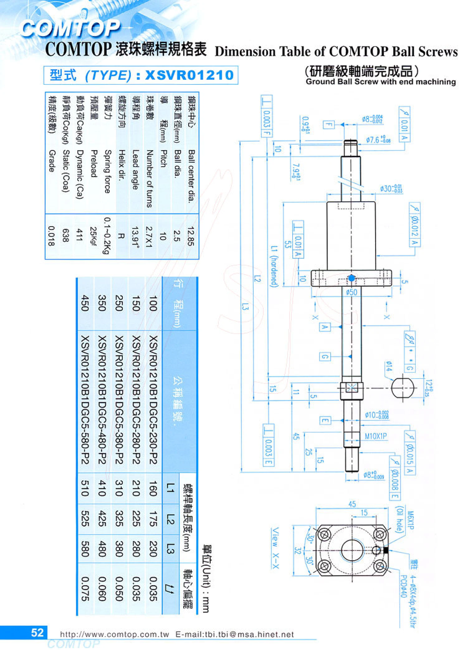
XSVR Series Precision Ground Ball Screws with Finished Shaft Ends
The XSVR series consists of precision ground ball screws supplied with both shaft ends fully machined, including bearing support journals, threaded locking sections, and coupling mounting sections. No additional end machining is required during installation; support units and couplings can be fitted directly, shortening assembly time while ensuring shaft-end runout and concentricity. The precision grinding process provides better lead accuracy, axial clearance, and surface finish than rolled ball screws. These products are suitable for machine tool feeds, precision slides, automation modules, and other applications requiring high positioning accuracy and repeatability. Key selection criteria include nominal diameter, lead, lead accuracy grade, nut type (flanged, cylindrical, internal circulation, or external circulation), axial clearance or preload grade, overall screw length and effective travel, shaft-end configuration, and support bearing model. Products in this series are specified by their complete model numbers, such as XSVR01210. Confirm the exact diameter, lead, and shaft-end dimensions using the drawing for the relevant model.
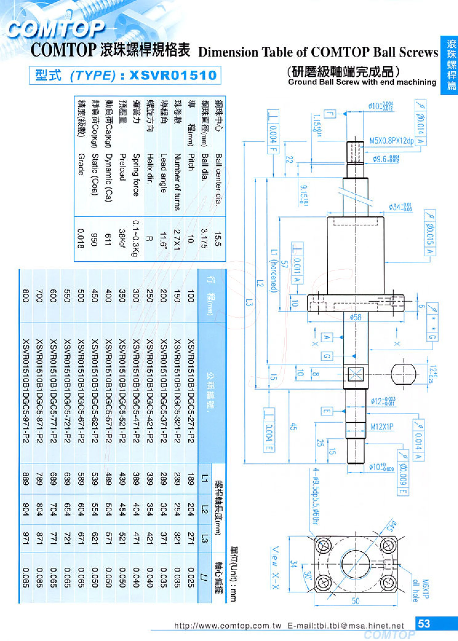
COMTOP XSVR01510 Series Ball Screws
The COMTOP XSVR01510 is a precision-ground ball screw with pre-machined shaft ends, designed for automated equipment requiring high-precision linear motion. The shaft ends are machined at the factory for direct installation with support units, couplings, motors and other components, reducing the need for secondary machining. The grinding process provides high lead accuracy and smooth operation, making the series suitable for machine tools, semiconductor equipment and precision measurement platforms. When selecting a model, confirm the nominal diameter, lead, thread length, shaft end configuration and accuracy grade.
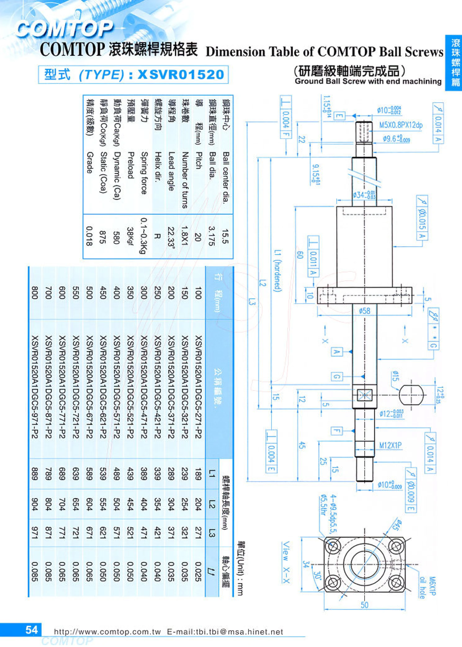
XSVRO Series Ball Screws
This catalog page provides a specification table for the XSVRO1520 ball screw in the XSVRO series, listing dimensional data by one-way travel (mm). Ball screws convert rotary motion into linear motion and are commonly used in automation equipment, machine tools, precision positioning mechanisms, and linear drive systems. Selection typically requires confirmation of the nominal diameter, lead, accuracy grade, axial clearance, dynamic and static load ratings, travel range, and mounting method. The table on this page could not be fully reconstructed by OCR. Specific travel values and detailed dimensions should be verified against the complete catalog page or the manufacturer's documentation.
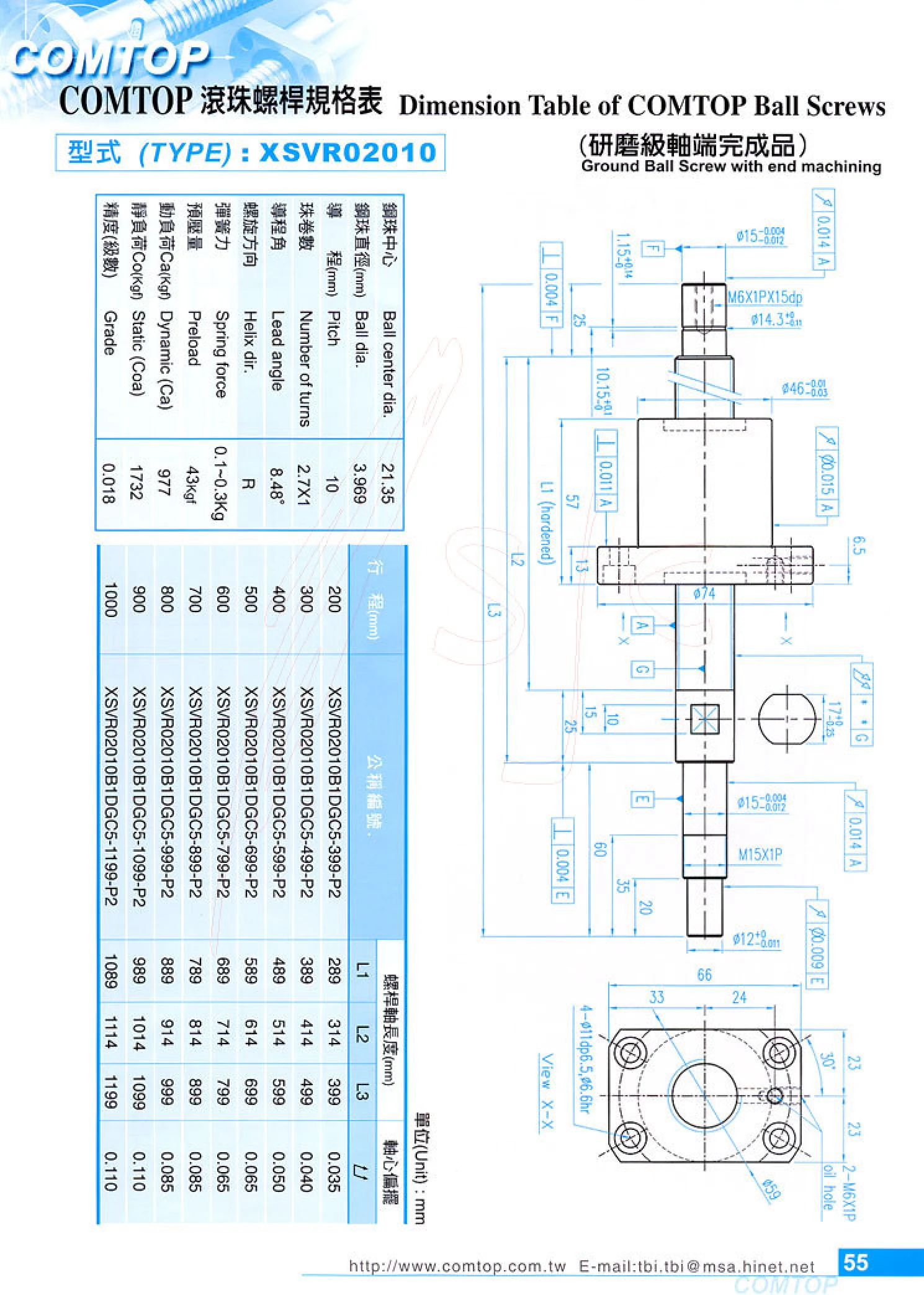
XSVR Series Ground Ball Screws with Machined Ends
The XSVR series consists of ground ball screws with machined ends. The screw shaft and nut are precision-ground, and the shaft ends, including bearing seats, coupling connections, and locking threads, are machined so no secondary end machining is required before installation. The series is suited to applications requiring high positioning accuracy, repeatability, and drive rigidity, such as CNC machine tool feed axes, precision measurement platforms, automated linear modules, and semiconductor equipment. Key specifications include nominal shaft diameter, lead, accuracy grade, axial clearance (preload grade), threaded length, and support-side end configuration. Typically made from high-carbon chromium bearing steel or alloy steel, the components are quenched, tempered, and precision-ground for high surface hardness, low friction, quiet operation, and long service life. When selecting a model, confirm the shaft diameter and lead combination, accuracy grade, and load conditions, and specify the machining dimensions for both ends using the shaft-end configuration codes in the catalog.
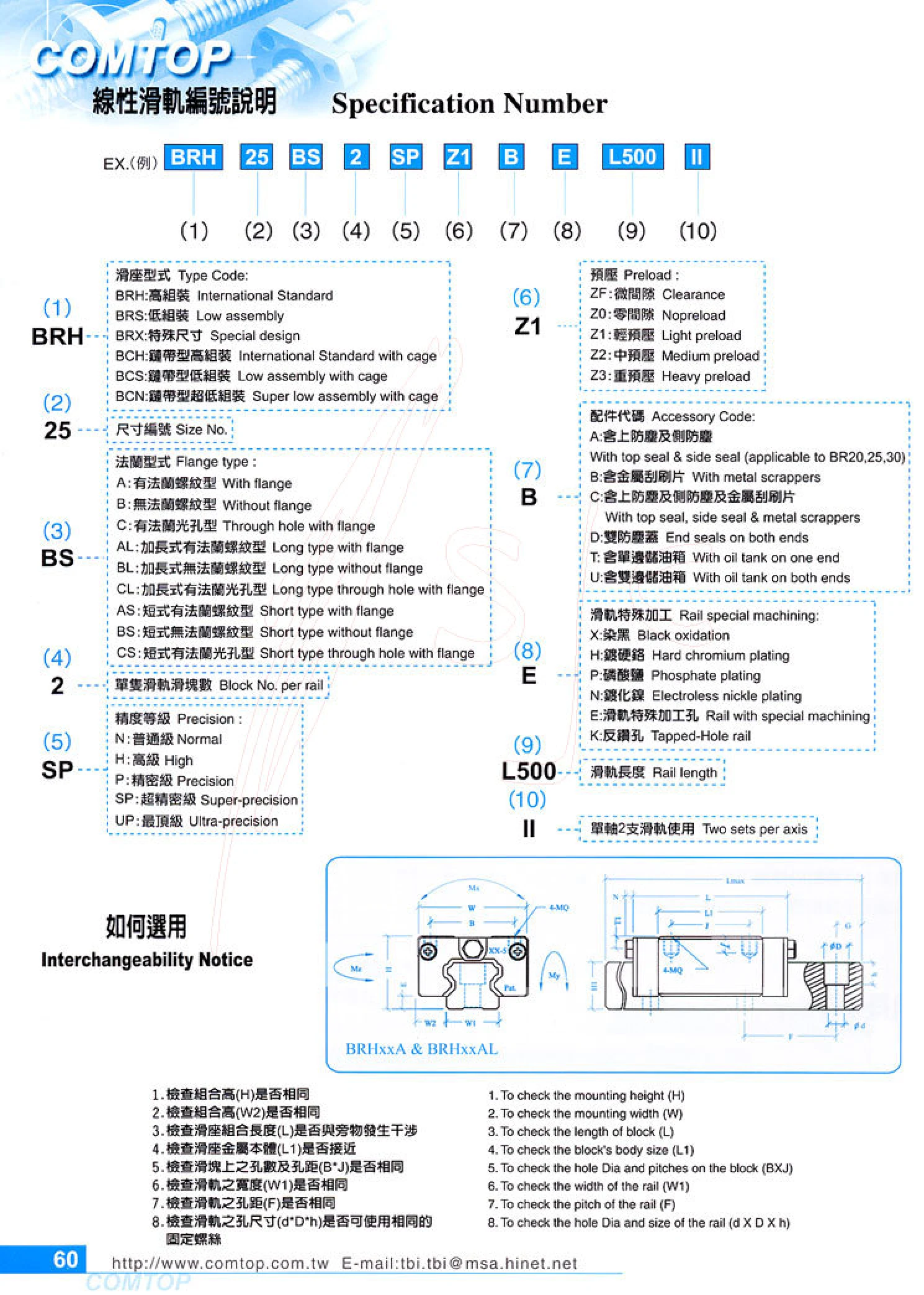
BRH Series Linear Guides
The BRH series consists of high-profile (international standard) linear guides. The same numbering system also covers BRH high-profile, BRS low-profile, BRX special-size, and BCH/BCS/BCN thin-strip carriage types (with retaining chain). The model number is formed by combining, in order, the carriage type, size number (such as 20/25/30), flange type (flanged with threaded holes A, flangeless with threaded holes B, or flanged with through holes C, with extended AL/BL/CL and short AS/BS/CS versions), number of carriages per rail, accuracy grade (N/H/P/SP/UP), preload (ZF slight clearance, Z0 zero clearance, Z1 light preload, Z2 medium preload, Z3 heavy preload), accessory codes (top and side dust seals, metal scraper plates, double dust covers, and single/double-sided locking clips), special rail treatments or machining (blackening, hard chrome plating, phosphating, electrolytic nickel plating, specially machined holes, and reverse-drilled holes), rail length (L followed by a number), and the II designation for two rails on one axis. When selecting a replacement, check that the five dimensions—assembly height H, assembly width W2, carriage assembly length L, rail width W1, and rail hole pitch F—match, to
BRS Series Linear Guideways
The BRS series is a low-profile linear guideway with a reduced carriage height, making it suitable for installations with limited space. It uses four rows of load-bearing balls to provide high rigidity and precision. The model code specifies the carriage type, size, flange type, number of guide rails, accuracy grade, preload, accessory code, special rail machining, and rail length. Five accuracy grades are available: N, H, P, SP, and UP. Five preload grades are available: ZF, Z0, Z1, Z2, and Z3. Flange types include A, B, C, AL, BL, CL, AS, BS, and CS, offering mounting options for a range of equipment.

Standard AN-Type Locking Nuts
AN-type standard locking nuts feature a simple design, with the internal thread and end face machined simultaneously to ensure the required runout accuracy. Thread specifications range from M10×0.75p to M200×3.0p, with 38 models available. Outer diameter D ranges from 18mm to 250mm, height h from 4mm to 29mm, groove width g from 3mm to 18mm, keyway depth t from 2mm to 18mm, and hole diameter d from 2mm to 8mm. Suitable for precision machinery locking applications. Non-standard nuts can be customized.
BRX Series Linear Guideways
BRX is a linear guideway series with specially sized blocks. The series designation consists of the block type, size number, flange type, number of guide rails per axis, accuracy grade, preload, accessory code, special rail machining, rail length, and use of 2 guide rails on a single axis. Flange options include flanged and non-flanged, extended and short, and combinations of through-holes and threaded holes. Accuracy grades include normal, high, precision, super precision, and ultra precision. Preload ranges from slight clearance to heavy preload. Accessories include dust protection, scrapers, double dust covers, and grease nipples. Rails can be blackened, hard chrome plated, phosphated, nickel electroplated, or supplied with specially machined or reverse-drilled holes. Suitable for linear motion mechanisms requiring special mounting dimensions.
BCH Series Linear Guides
The BCH series consists of thin-strip, high-profile linear guides (International Standard with cage). Their recirculating ball design uses a ball cage and provides high load capacity and running accuracy, making them suitable for linear guidance in automation equipment and precision machinery. The product number consists of 10 segments: carriage type, size code, flange type, number of carriages per rail, accuracy grade, preload, accessory code, special rail processing, rail length, and single-axis use designation. Accuracy grades are normal N, high H, precision P, super precision SP, and ultra precision UP. Preload options are slight clearance ZF, zero clearance Z0, light preload Z1, medium preload Z2, and heavy preload Z3. Flange types include A/B/C, extended AL/BL/CL, and short AS/BS/CS. Accessory codes A~U cover options such as dust caps, metal scrapers, and locking clips. Special rail processing includes blackening, chrome plating, phosphating, electrolytic nickel plating, specially machined holes, and reverse-drilled holes.
BCS Series Linear Guides
The BCS series is a low-profile, thin-strip linear guide with a cage, part of the BRH/BRS/BRX/BCH/BCS/BCN linear guide family. The carriage uses a cage to retain the steel balls as they recirculate, delivering smoother, quieter operation and longer service life. Its low-profile construction reduces installation height, making it suitable for precision linear motion applications with noise and space constraints. The ordering designation consists of 10 code segments: carriage type (BCS), size number, flange type, number of carriages per rail, accuracy grade (N/H/P/SP/UP), preload grade (ZF/Z0/Z1/Z2/Z3), accessory code, special rail machining, rail length (L+length, mm), and an identifier for two rails used on a single axis. These products are widely used in CNC machine tools, semiconductor equipment, automated production lines, measuring instruments, and other precision linear motion applications.
BCN Series Linear Guideways
The BCN series consists of ultra-low-profile linear guideways with a sealing strip and an integrated ball cage. The carriage assembly height is lower than that of a conventional guideway of the same size, making it suitable for space-constrained automation equipment and miniature mechanisms. The cage separates and guides the steel balls as they recirculate, providing low friction, smooth operation, low noise and long service life. The sealing strip blocks contaminants and reduces grease leakage. The series offers flanged threaded, non-flanged threaded and flanged through-hole types, as well as various extended (AL/BL/CL) and short (AS/BS/CS) flange styles. Accuracy grades include N standard, H high, P precision, SP super precision and UP ultra precision. Preload options are ZF slight clearance, Z0 zero clearance, Z1 light preload, Z2 medium preload and Z3 heavy preload. Optional accessories include top and side dust seals, metal scrapers, double dust seals and lubrication grooves on one or both sides. Rails can be supplied with black oxide, hard chrome, phosphate or electrolytic nickel finishes, as well as specially machined holes and reverse-drilled holes. Rail lengths are customized to travel requirements, and two rails can be configured on a single axis.
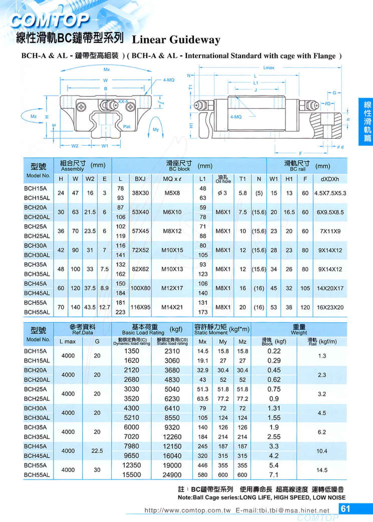
BCH-A & AL Ball Chain Linear Guideways
The BCH-A & AL series consists of ball chain (BC) linear guideways with a ball chain retention system, a high-profile flange-mounted design, and dimensions compliant with international standards. The chain prevents balls from falling out and reduces friction and noise for smoother carriage travel. These guideways are suitable for linear motion applications in automation equipment, machine tools, electronics manufacturing, material handling, and precision positioning. The series includes BCH-A and BCH-AL carriage types, with specifications selected according to assembly, carriage, and rail dimensions.
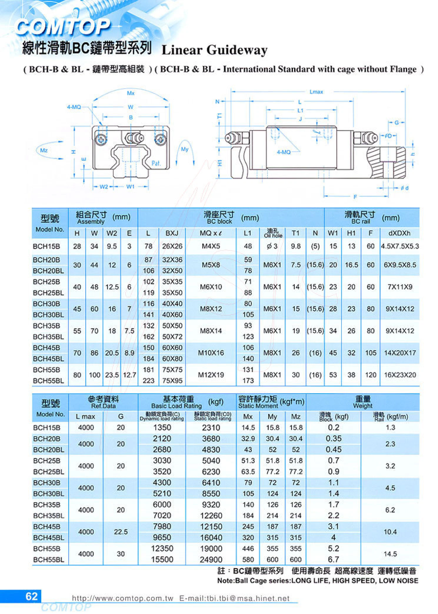
BCH-B & BL Series Ball Chain Linear Guides
The BCH-B and BL series are ball chain linear guides with a flangeless design and internationally standardized mounting dimensions. A retaining chain controls ball recirculation, keeping the balls evenly spaced inside the carriage and preventing them from pressing against or rubbing against one another. This reduces rolling resistance and noise while improving recirculation stability and service life at high speeds. The series is supplied in high assembly accuracy grades and is suitable for automation equipment, machine tools, electronics assembly, handling systems, and other applications requiring quiet, high-precision linear guidance. Complete selection depends on the nominal carriage and rail size (cross-sectional dimensions), accuracy grade, preload grade, rail length, and mounting hole spacing. Refer to the dimensional tables in the catalog for specific specifications.
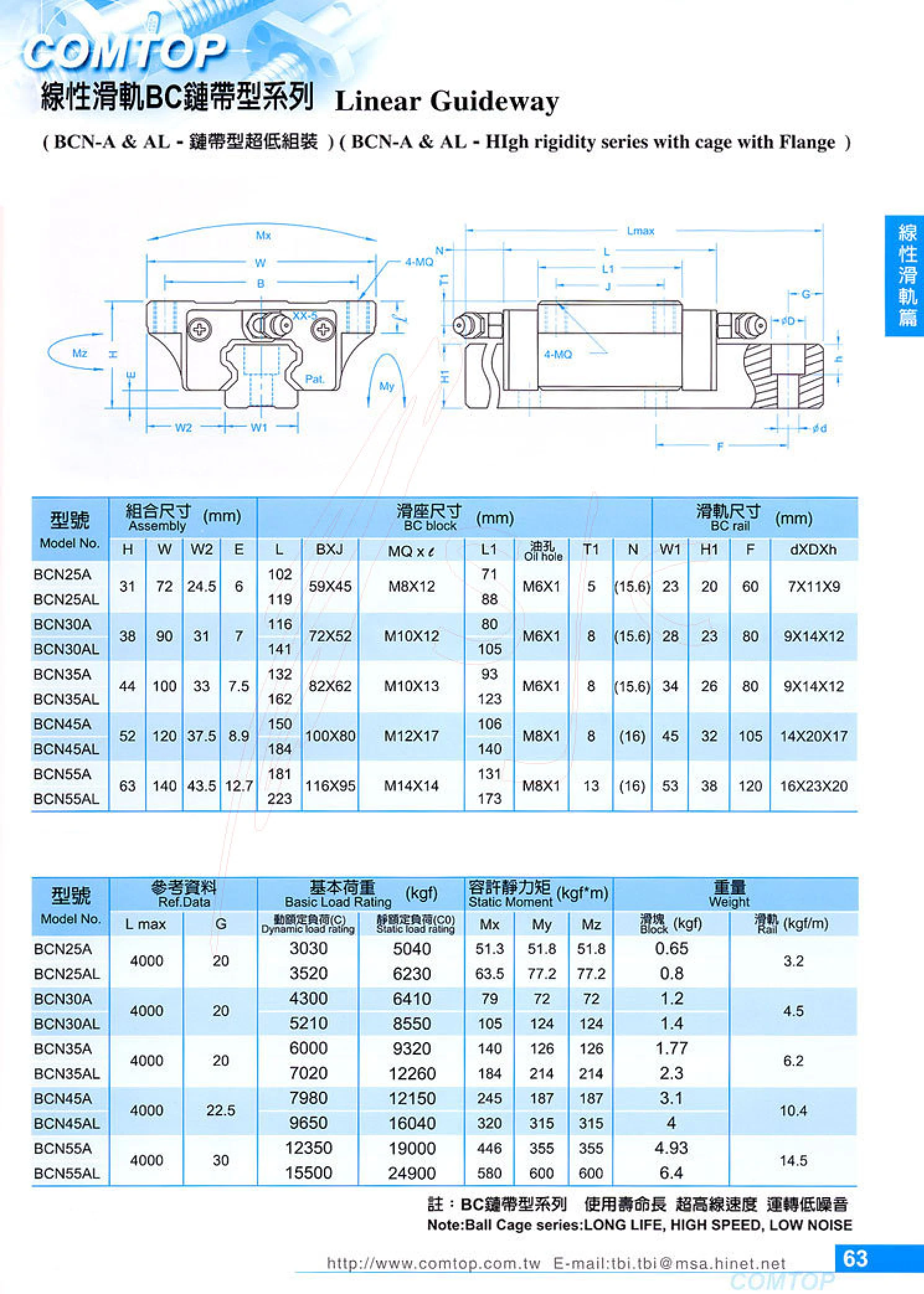
BCN Series Ball Chain Linear Guides
The BCN series consists of ball chain linear guides, including the standard BCN-A and extended BCN-AL models. They feature flange mounting, an ultra-low assembly height, and a high-rigidity structure. The ball chain retains the balls for long service life, very high linear speeds, and quiet operation. The catalog covers sizes 25, 30, 35, and 45, with assembly height H of approximately 31~63 mm, assembly width W of approximately 72~140 mm, and a maximum reference length of 4000 mm. It also specifies dynamic and static load ratings, allowable static moments, and weights. Suitable for automation equipment, precision positioning, machine tools, and high-speed linear motion systems.
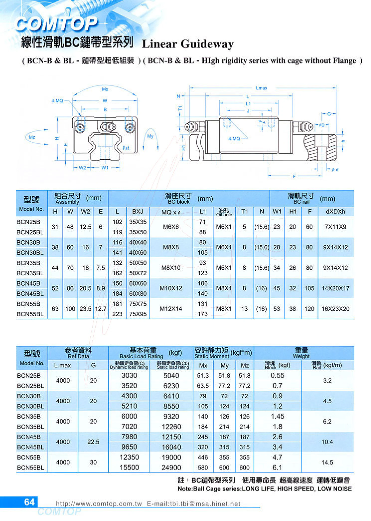
BCN-B & BL Series Ball-Chain Linear Guides
The BCN-B & BL series consists of ultra-low-profile ball-chain linear guides with a flangeless BC block design. They are available in standard B and extended BL versions. The ball retainer keeps the steel balls rolling in an orderly manner during recirculation, providing long service life, ultra-high linear speeds, and low noise. Five sizes are available: 25, 30, 35, 45, and 55, with heights H of 31~63mm and widths W of 48~100mm. Basic dynamic load ratings range from 3030~15500 kgf and static load ratings from 5040~24900 kgf. Allowable static moments are specified in the Mx/My/Mz directions, and maximum rail length is 4000mm. These guides are suitable for high-speed, high-precision, low-noise linear motion in automated equipment.
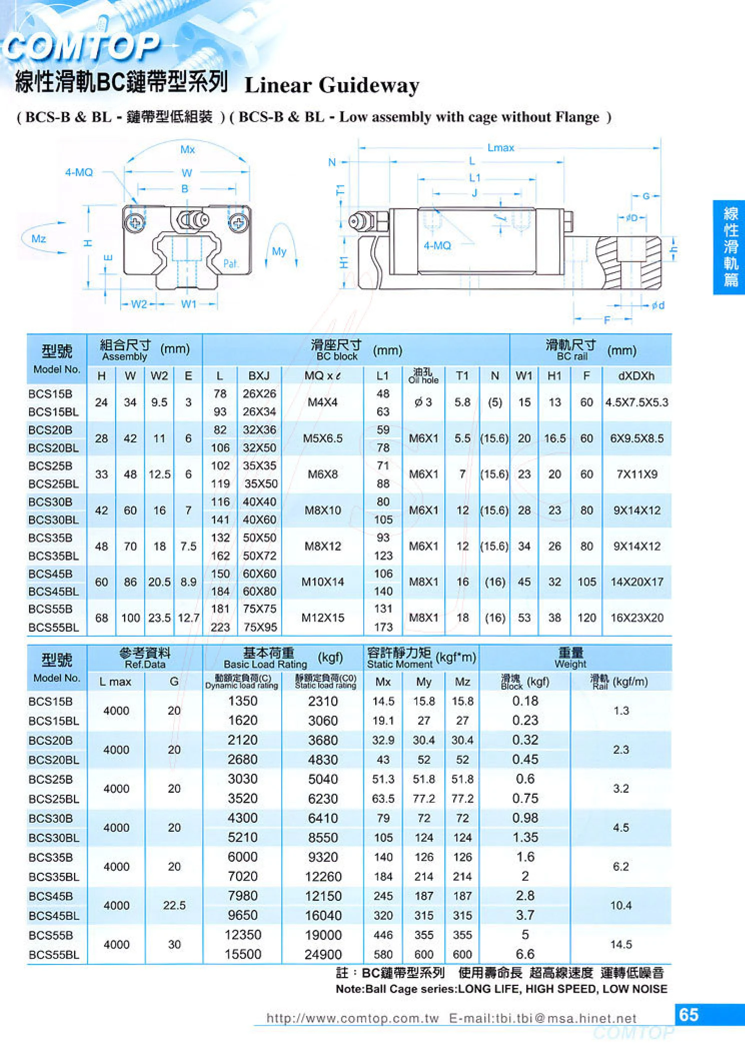
BCS-B & BL Series Low-Profile Linear Guides with Ball Chain
The BCS-B & BL series consists of low-profile linear guides with ball chain retainers that prevent the steel balls from falling out during operation. They offer a low mounting height, high rigidity, low noise and high-precision linear motion. The series includes BCS-B and BL models, both with flangeless mounting designs, suitable for automation equipment, precision machine tools, semiconductor equipment and other applications with limited mounting height and demanding motion accuracy requirements. Refer to the catalog tables for dimensions, load ratings, accuracy grades and other specifications.
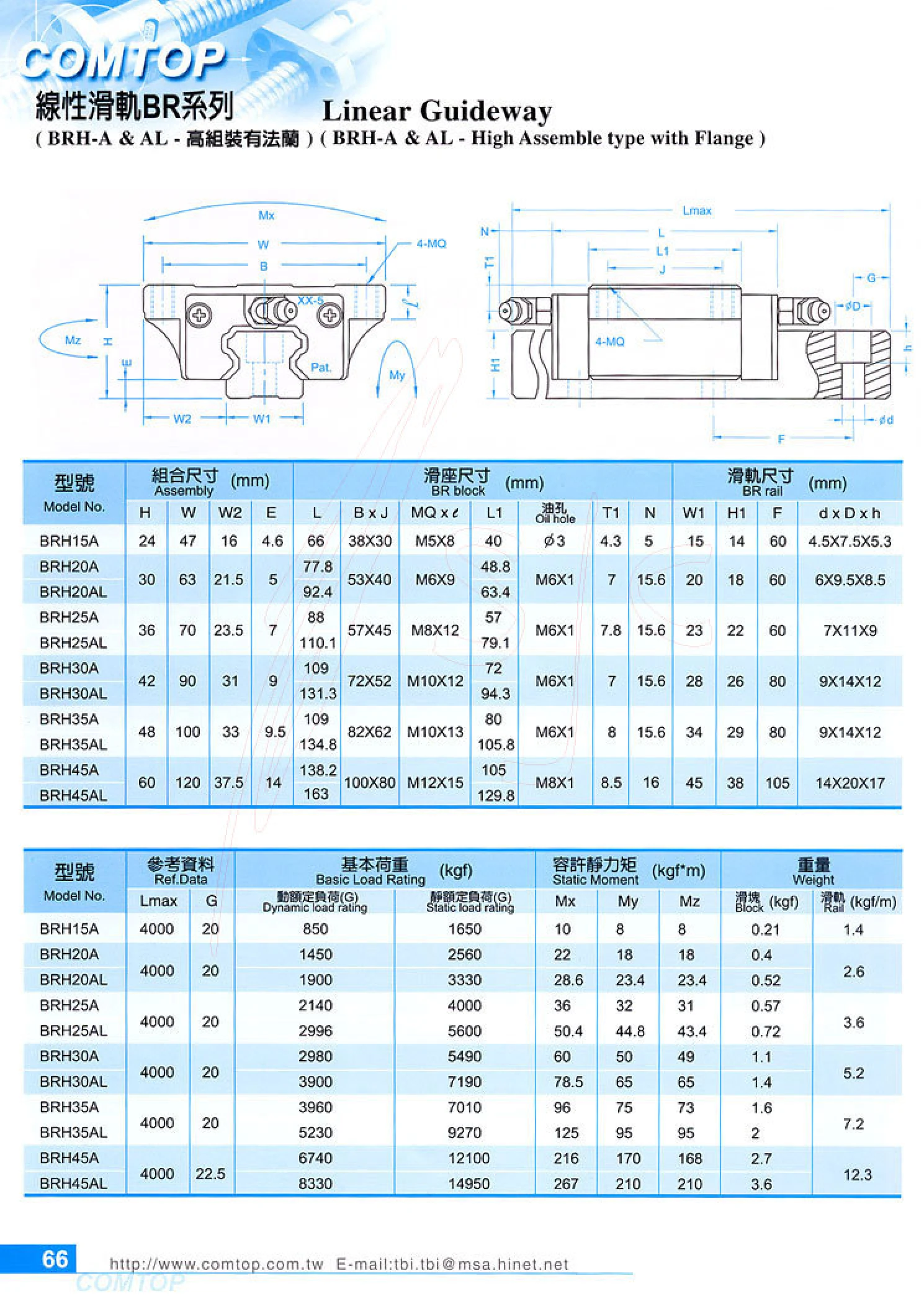
BR Series Linear Guideways
BR series linear guideways are available in high- and low-profile, flanged and non-flanged, and through-hole and threaded-hole configurations. Common variants include BRH-A/AL, BRH-B/BL, BRS-B/BL/BS, BRH-C/CL and BRX-B/BL. The catalog defines specifications using parameters such as assembly dimensions H/W/W2/E, block dimensions L/B×J, rail dimensions W1/H1/F, and mounting hole dimensions d×D×h. BRX25B/BRX25BL are non-flanged models with special dimensions: assembly height 36 mm, assembly width 48 mm, block length 88 mm, oil hole M6×1, maximum rail length 4000 mm, dynamic load rating 2140 kgf and static load rating 4000 kgf. They are suitable for linear guidance in automation equipment, machine tools, conveyors and similar applications.
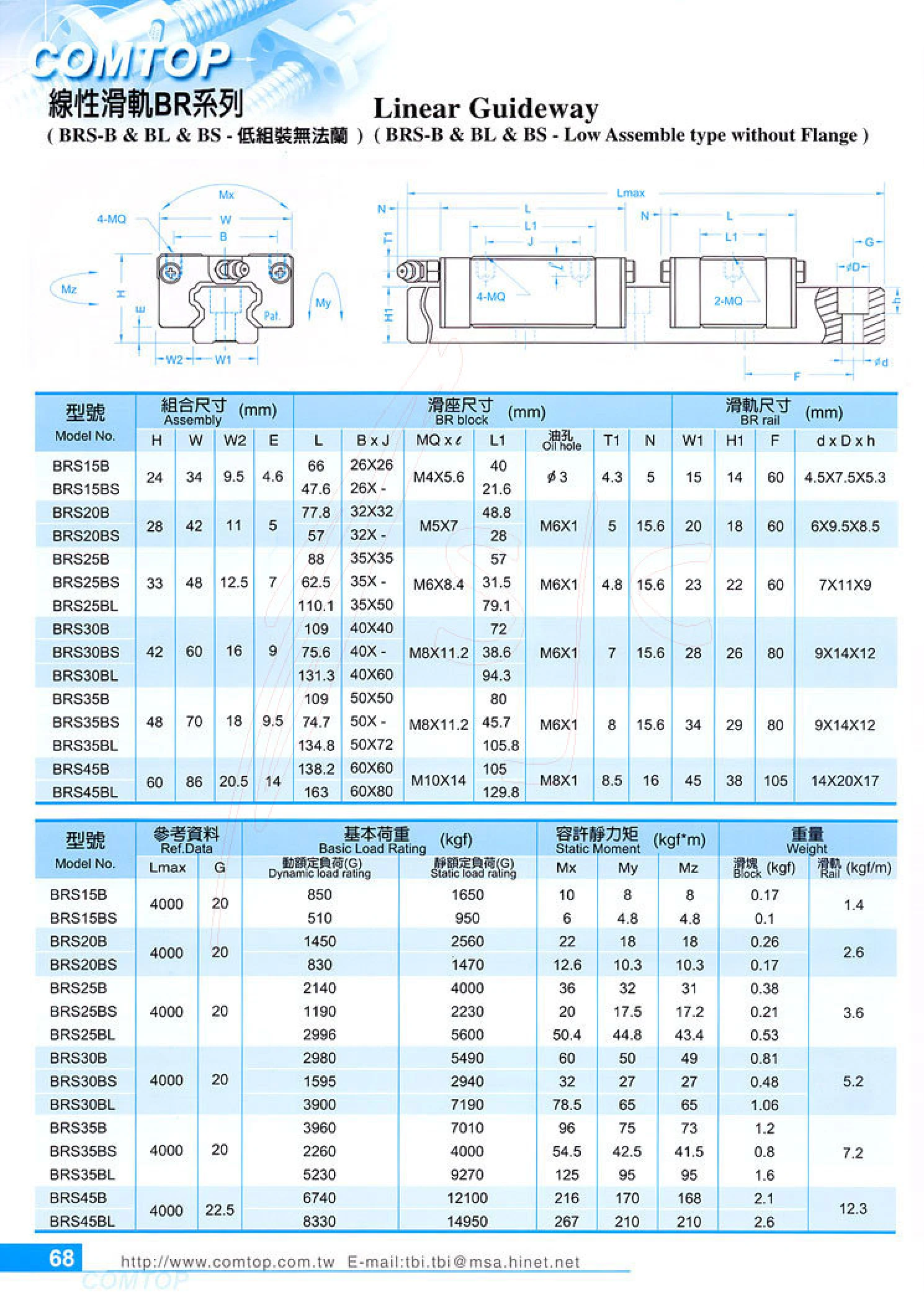
BRS-B Series Linear Guideways
The BRS-B series is a low-profile, flangeless carriage type in the BR series of linear guideways. Like the BL and BS series, it belongs to the low-profile linear guideway family. Its carriage has a low cross-sectional height and no flange on the mounting surface, making it suitable for height-sensitive, space-constrained applications requiring mounting from the side or above. It is commonly used for linear guidance in automation equipment, compact positioning stages, inspection mechanisms, and material handling systems. Product specifications are organized into two categories: assembly dimensions and carriage dimensions. Assembly dimensions include rail width, assembled carriage and rail height, and mounting hole spacing. Carriage dimensions include length, width, height, mounting thread specifications, and hole spacing. Select the carriage size according to load, moment, and accuracy requirements, and cut the rail to length according to the required travel. The catalog page provided contains only table headers and repeated column headings; the dimensional values for specific models are missing. Refer to the complete catalog table for actual model codes and dimensions.
BL Series Linear Guideways
The BL series consists of low-profile, flangeless linear guideways that share a common dimensional system with the BRS-B and BS subseries in the same catalog. Their low assembly height allows them to be mounted directly on a low mounting surface, making them suitable for applications with strict overall height limits. The catalog provides tables of assembly dimensions (mm) and carriage dimensions (mm) for each model, including rail width, assembly height, carriage length and width, mounting hole spacing, and rated dynamic and static loads. These values can be used to compare available installation space and load capacity when selecting a model. The main differences between submodels in the series are whether the carriage has a flange, the assembly height, and the mounting hole layout. Select a model based on load, travel, accuracy grade, and assembly height, then specify the required rail length separately.
BR Series Linear Guideways
The BR Series linear guideway is a low-profile, flangeless linear guide assembly. The catalog distinguishes three block configurations: BRS-B, BL and BS. All feature a low-profile, flangeless design suitable for automated equipment with limited installation height and a need for compact layouts. Selection is primarily based on two sets of parameters: assembly dimensions and block dimensions. Assembly dimensions describe the overall height, width and other external dimensions of the assembled rail and block. Block dimensions describe the block's length, width, height, mounting hole spacing, and interfaces for lubrication and dust protection accessories. The series is typically available with blocks and rails in different accuracy and preload grades, and rails can be cut to suit the required travel length. This catalog page consists mainly of dimensional tables, with the heading “Block Dimensions (mm)” repeated across the columns. The numerical values were lost during OCR, so this entry retains only basic information about the series and block submodels. For actual selection, refer to the dimensional tables in the original catalog or the product drawings.
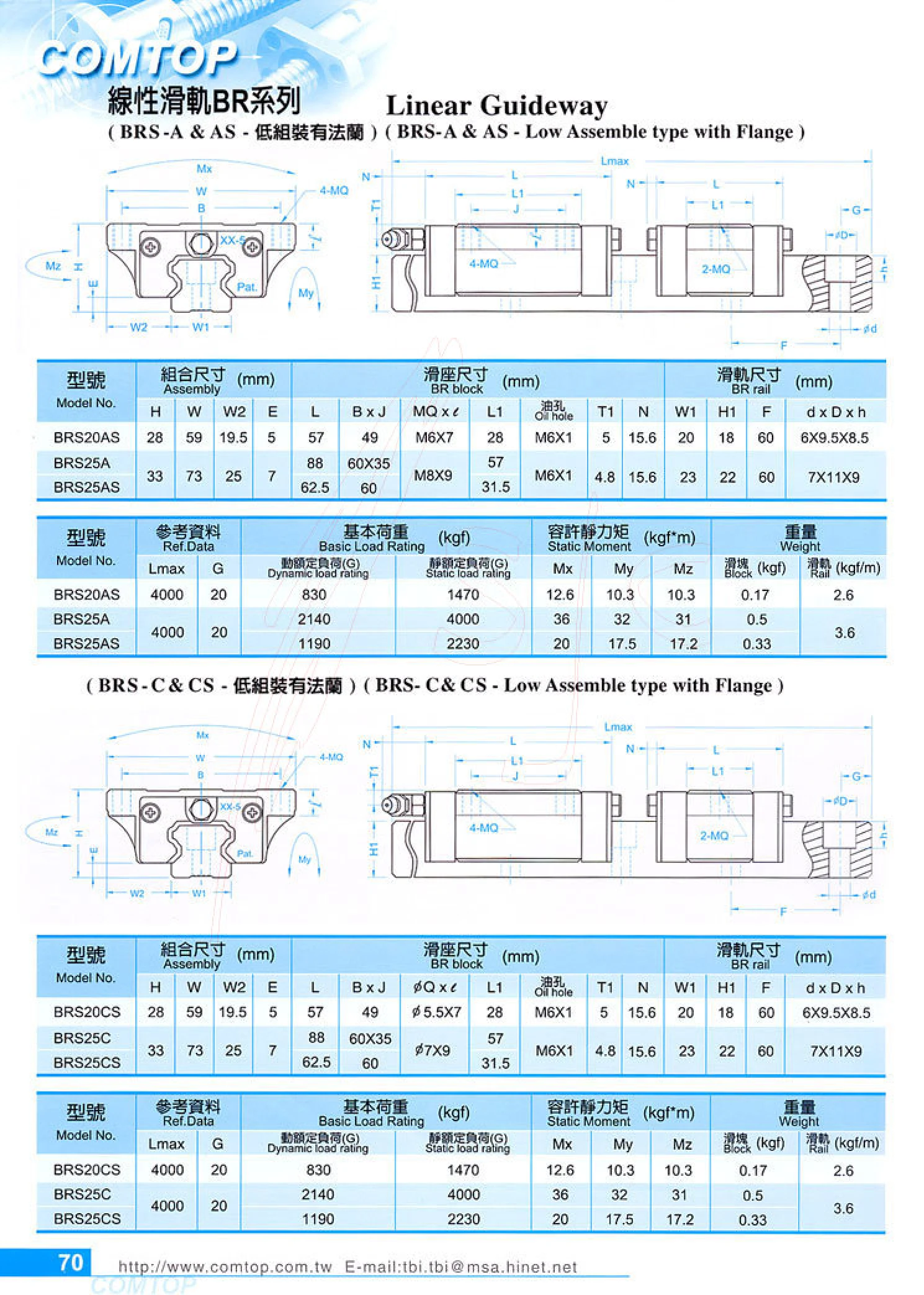
BR Series Linear Guides
BR series linear guides are ball-type linear guides, represented in the catalog by the BRS-A and BRS-AS low-profile flanged carriage models. Steel balls recirculate between the rail and carriage, providing low friction and high positioning accuracy. The guides can support loads in four directions: radial, reverse radial and both lateral directions. They are suitable for linear guidance in automation equipment, precision machine tools, and semiconductor and electronics manufacturing equipment. Specifications are organized into three categories: assembly dimensions (mm), carriage dimensions (mm) and rail dimensions (mm). The catalog lists values for each size, including assembly height and width, carriage length, mounting hole spacing, rail width and thickness, and dynamic and static load ratings, making it easy to check mounting interfaces and load capacity during selection. The flanged carriage can be bolted down from above, while the low-profile design reduces overall machine height and saves installation space. Rails can be cut to suit the required travel or supplied in standard lengths, and multiple rails can be joined end to end.
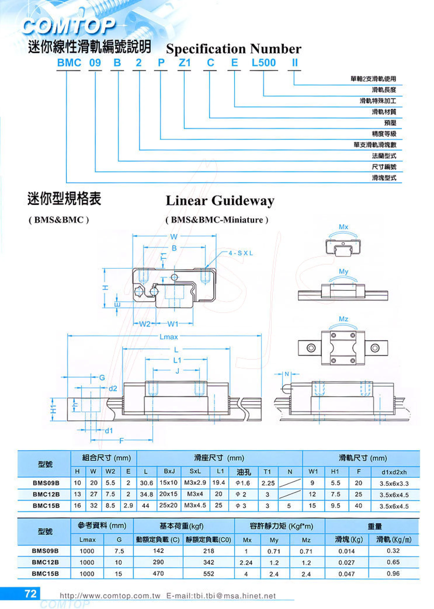
BMS&BMC Series Miniature Linear Guides
The BMS&BMC series comprises miniature linear guides for linear motion in compact automation equipment, precision instruments and electronics manufacturing equipment. The model code specifies the block type, size number, flange type, number of blocks per rail, accuracy grade, preload, rail material, special rail machining, rail length and two-rail-per-axis configuration. The catalog provides assembly, block and rail dimensions, with various lengths and configurations available to suit the space in the equipment.
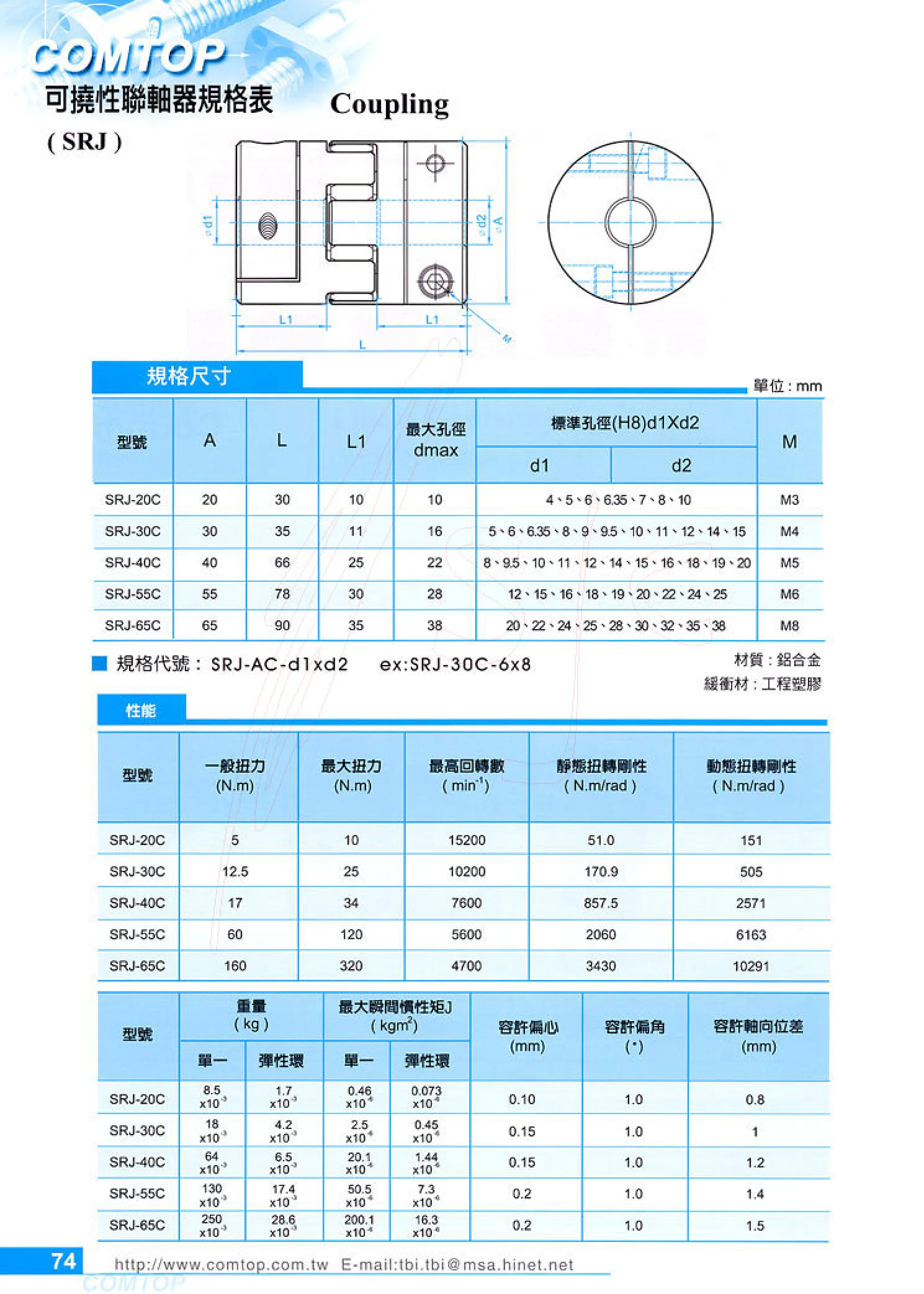
SRJ Series Flexible Couplings
SRJ series flexible couplings (elastic couplings) feature aluminum alloy hubs and an engineering plastic cushioning element. They provide a flexible connection between servo motors and ball screws or gear reducers, compensating for radial, angular, and axial misalignment while absorbing vibration and shock. Five sizes are available, with outer diameters of 20/30/40/55/65 mm, lengths of 30~90 mm, and maximum bore diameters of 10~38 mm. Standard bores are available in sizes from 4~38 mm with an H8 tolerance. The bore diameter at each end can be specified separately (e.g., SRJ-30C-6×8). Rated torque is 5~160 N·m, maximum torque is 10~320 N·m, maximum speed is 4700~15200 min⁻¹, static torsional stiffness is 51~3430 N·m/rad, dynamic torsional stiffness is 151~10291 N·m/rad, and weight is 8.5 g~250 g. They are suitable for high-speed, high-precision, zero-backlash positioning applications.

BF Series Bearing Housings
The BF series comprises support-side (floating-side) bearing housings for screw support units. They are commonly paired with BK series fixed-side support units to provide additional support at the end of a ball screw while allowing axial displacement caused by thermal expansion. The one-piece cast or steel housing has a mounting base with two holes for direct bolting to a machine tool or automation equipment mounting surface. It contains a deep-groove ball bearing that is pre-greased at the factory. Nine nominal models are available, from BF10~BF40, covering shaft diameters d1 of 8~40mm, overall widths B of 60~160mm, overall heights H of 39~110mm, mounting hole center distances P of 46~130mm, and mounting hole diameters d2 of 5.5~14mm. Select the model based on the nominal screw diameter and available mounting space. The dimension symbols L, B, H, b, h, B1, H1, E, P, d2, X, Y and Z in the table correspond to those in the catalog drawing; all dimensions are in mm.

EF Series Ball Screw Support Units
The EF series comprises support-side (floating-side) units for ball screws, used with fixed-side units (EK series). They support radial loads at the ball screw shaft end while allowing axial expansion caused by operating temperature rises. The square flanged housing is secured to the equipment surface through two mounting holes for easy installation and alignment. Six sizes are available for screw shaft end diameters d1 of 6~20 mm: EF6, EF8, EF10, EF12, EF15 and EF20. Key dimensions include housing width B 42~95 mm, height H 25~58 mm, housing thickness L 12~26 mm, mounting hole pitch P 30~75 mm and mounting hole diameter X 5.5~11 mm. The EF6 and EF8 sizes have counterbored holes (counterbore diameter Y of 9.5 mm or 11 mm and counterbore depth Z of 11 mm or 12 mm). Select the nominal model according to the screw shaft end diameter d1, and check B, H, P and the mounting surface dimensions. This series is commonly used in ball screw drives for CNC machine tools and precision automation equipment. All dimensions
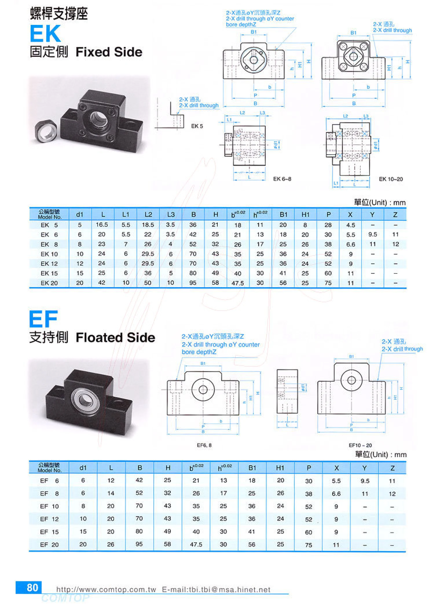
EK/EF Series Ball Screw Support Units
EK/EF series support units support the bearings at both ends of a ball screw, ensuring rotational accuracy and axial rigidity. The series comprises two mounting types: EK is the fixed side (square mounting), with paired angular contact bearings that carry axial and radial loads and preload the screw; EF is the support side (round flange mounting), with a deep groove ball bearing that provides radial support only, accommodating thermal expansion and mounting errors. Both types are specified by nominal shaft diameter d1, with seven sizes: 5, 6, 8, 10, 12, 15, and 20 mm. Specifications include axial dimensions L, L1, L2, and L3; mounting cross-section dimensions B, H, b, h, B1, and H1; bolt hole center spacing P; and positioning hole dimensions X, Y, and Z. The tolerance for b and h is 0.02 mm, facilitating selection to match the screw shaft end shoulder and locknut. Typical applications include CNC machine tools, precision measurement platforms, and automated positioning stages.
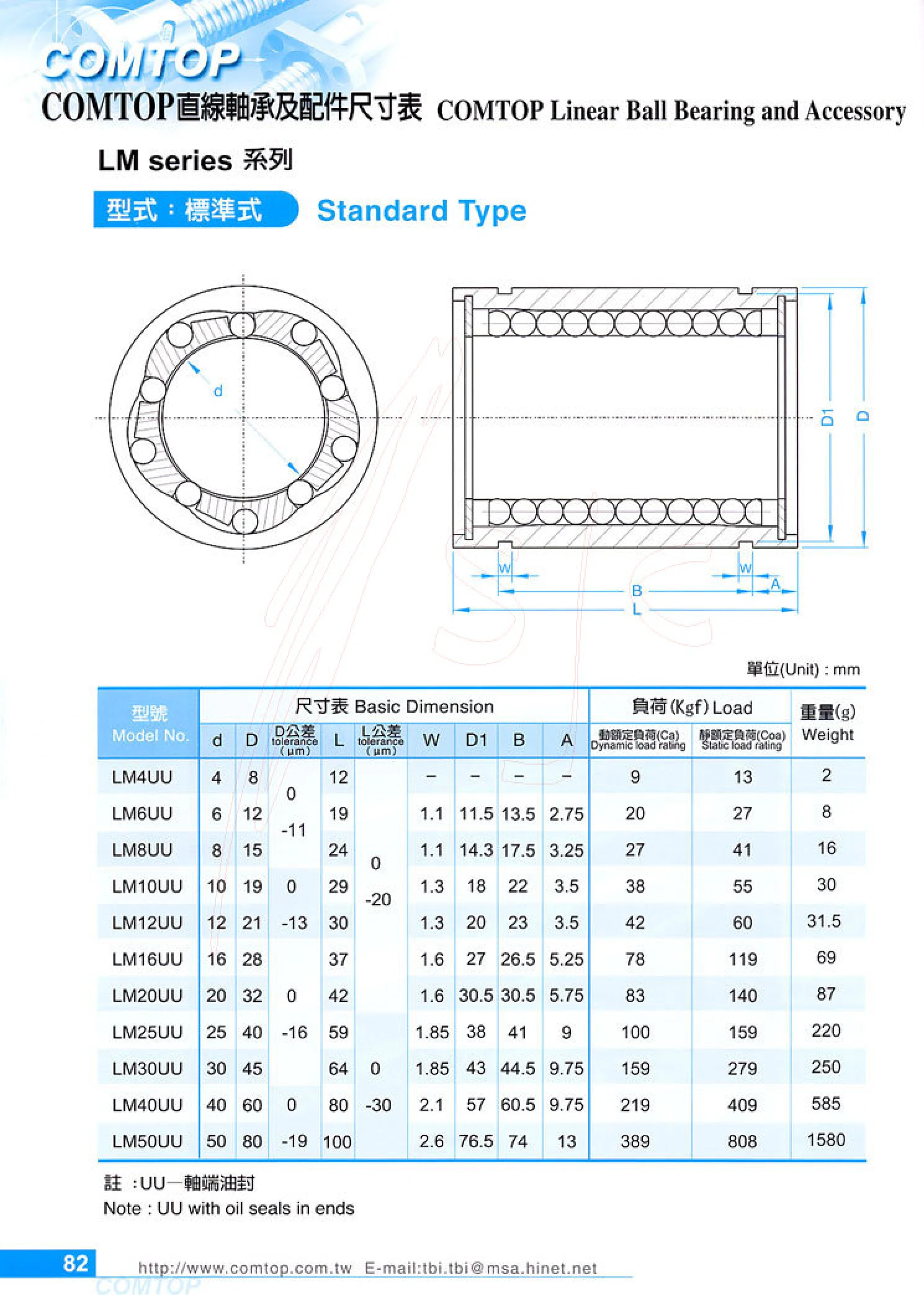
LM Series Linear Bearings
The COMTOP LM series consists of standard linear ball bearings made up of an outer cylindrical sleeve, a cage, and steel balls. Used with a hardened shaft, they provide high-precision linear reciprocating motion. The series includes 11 bore sizes: 4, 6, 8, 10, 12, 16, 20, 25, 30, 40, and 50 mm, with outer diameters of 8~80 mm and lengths of 12~100 mm. Dynamic load ratings range from 9~389 kgf, static load ratings from 13~808 kgf, and individual weights from 2~1580 g. The UU suffix throughout the series indicates seals at both ends to block dust and retain internal grease. These bearings have a simple construction, low friction, and good interchangeability. They are widely used in printers, packaging machinery, automated conveyor lines, and various light-duty linear guide mechanisms. Select the bore size based on the shaft diameter, then check the dynamic and static load ratings and available installation space.
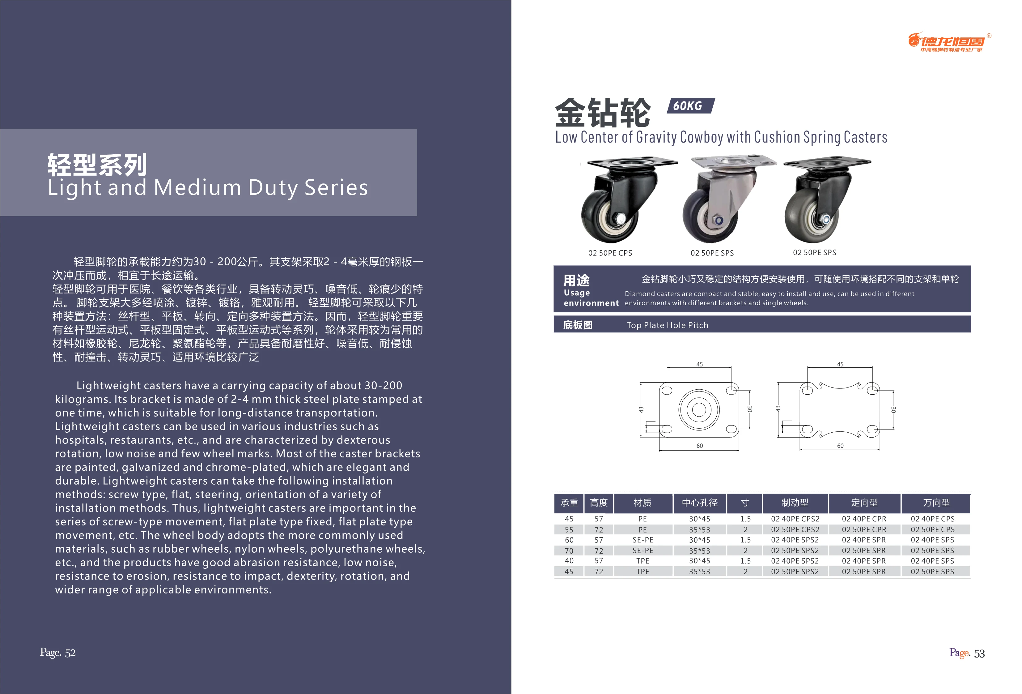
Golden Diamond Light-Duty Caster Series
The Golden Diamond Light-Duty Caster Series has a load capacity of approximately 30–200 kg. Its brackets are stamped in a single operation from 2–4 mm steel plate, making them suitable for long-distance transport. The casters swivel smoothly and quietly and leave minimal marks on floors. The brackets are powder-coated, galvanized, or chrome-plated for an attractive, durable finish. Mounting options include threaded-stem and top-plate types, with swivel and rigid configurations. Wheels are commonly made of rubber, nylon, or polyurethane, offering good wear resistance, quiet operation, corrosion resistance, and impact resistance. They are widely used in industries such as healthcare and food service. Model codes follow this format: the fixed prefix 02, followed by the wheel diameter and material (such as 40PE or 50PE), then the function type: braked (CPS2), rigid (CPR), or swivel (CPS), among others. Some models include spring cushioning (SPS2/SPR/SPS).
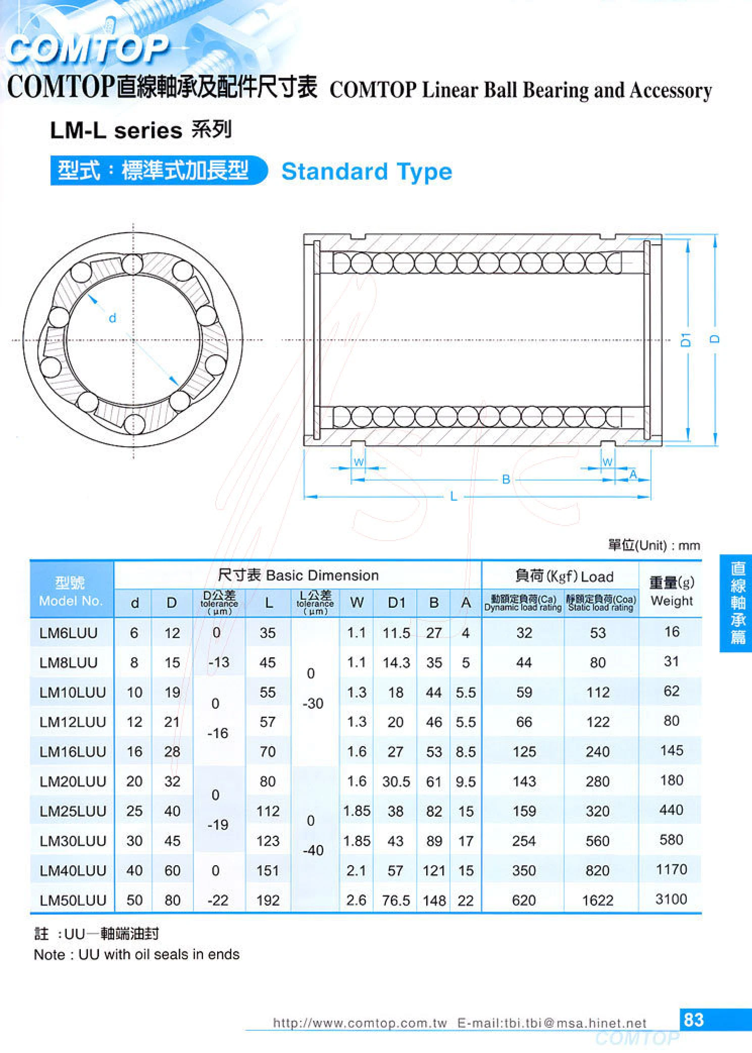
LM-L Series Long-Type Linear Bearings
The COMTOP LM-L series consists of standard long-type linear bearings with the standard LM series profile and an extended outer sleeve for improved guiding stability and load capacity. The nominal bore diameter d ranges from 6~50 mm, the outer diameter D from 12~80 mm, and the overall length L from 35~192 mm. In the model designation, L indicates the long type, and UU indicates shaft seals at both ends. The dimension table also lists outer diameter and length tolerances, W, D1, B, A, dynamic and static load ratings, and weight. These bearings guide reciprocating linear motion on linear shafts.
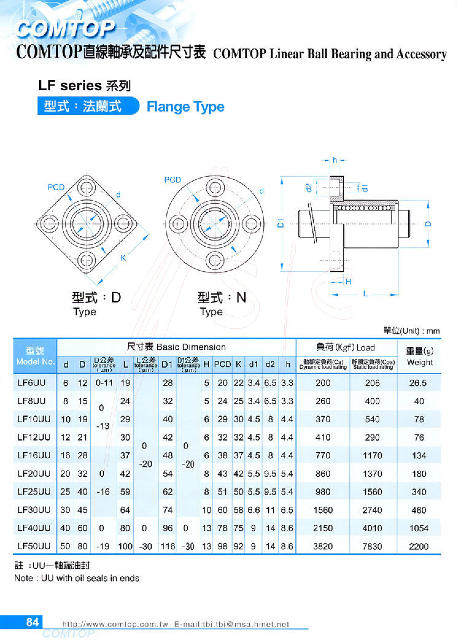
LF Series Flanged Linear Bearings
COMTOP LF series flanged linear bearings have mounting holes in the flange for direct bolting to vertical or horizontal mounting surfaces. They are suitable for reciprocating linear motion applications. Model numbers consist of LF + bore diameter + UU. Bore diameters range from 6~50 mm, flange outer diameters from 28~116 mm, overall lengths from 19~100 mm, and flange thicknesses from 5~13 mm. The mounting holes are counterbored, with hole diameters of 3.4~9 mm, counterbore diameters of 6.5~14 mm, and mounting hole pitch circle diameters (PCD) of 20~98 mm. All sizes have UU oil seals at both ends to keep dust out and retain internal grease. Dynamic load ratings range from 200~3820 N, static load ratings from 206~7830 N, and individual weights from 26.5~2200 g. These bearings offer low friction, smooth motion, high positioning accuracy, and good interchangeability. They are widely used in linear guide mechanisms for automation equipment, CNC machine tools, printing machinery, packaging lines, and more.
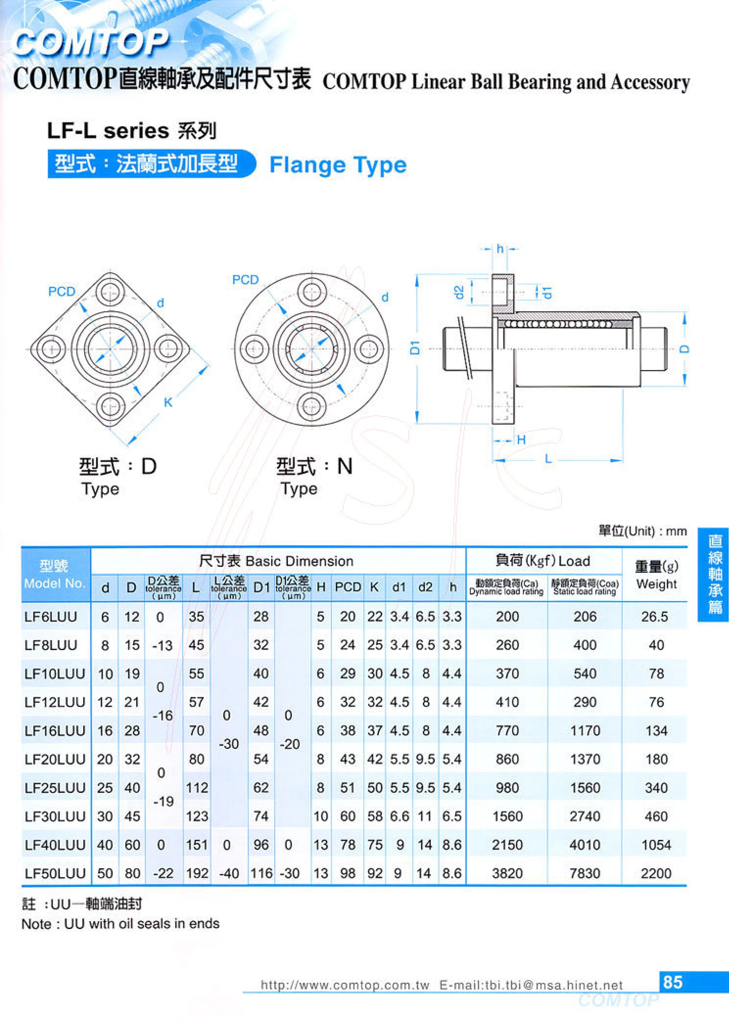
LF-L Series Long Flanged Linear Bearings
COMTOP LF-L series long flanged linear bearings feature a round mounting flange and are designed for reciprocating linear motion. Models range from LF6LUU to LF50LUU, with bore diameters of 6~50 mm, outside diameters of 12~80 mm, and lengths of 35~192 mm. Dynamic load ratings range from 200~3820 kgf, static load ratings from 206~7830 kgf, and weights from 26.5~2200 g. UU indicates seals at the shaft ends that keep dust out and retain grease. Common applications include automation equipment, precision guides, conveyors, and compact linear slides. Select a model based on shaft diameter, mounting hole spacing, and load requirements.
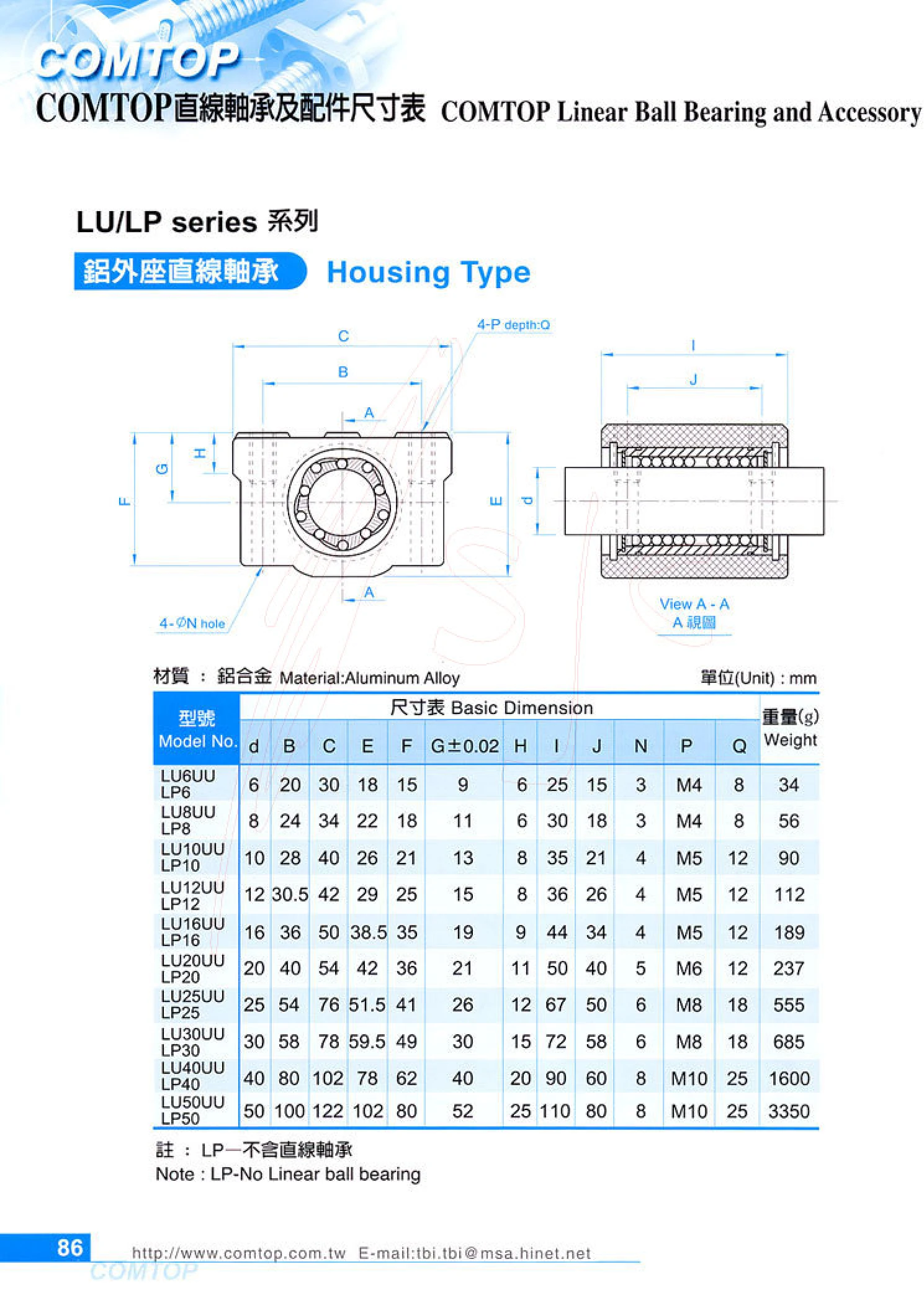
LU/LP Series Housed Linear Bearings
LU/LP series housed linear bearings feature aluminum alloy housings with an installed linear bearing or space for one, providing shaft support and guidance in linear reciprocating mechanisms. The series covers 10 sizes with bore diameters from d=6mm to 50mm. Overall and mounting dimensions are designated by B, C, E, F, G, H, I and J; mounting holes comprise N through-holes and P threads (M4~M10), with Q indicating the mounting hole center distance. Individual weights range from 34g to 3350g. Two types are available: LU is a complete assembly with a linear bearing (model suffix UU) and can be used directly with a shaft; LP is an aluminum alloy housing without a linear bearing (Note: LP—linear bearing not included) and must be fitted with a separate linear bearing of the appropriate bore diameter. The lightweight, rigid aluminum alloy housing is suitable for linear guide units in light- to medium-load applications such as automation equipment, conveyor lines and packaging machinery.
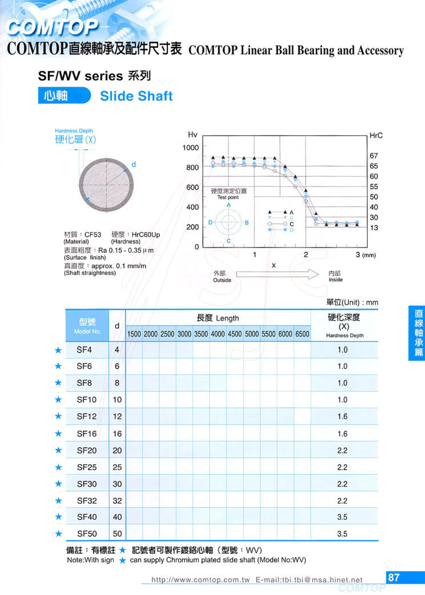
SF/WV Series Slide Shafts
SF/WV series slide shafts are designed for use with COMTOP linear bearings to provide linear guidance and reciprocating motion. They are suitable for automated linear motion applications with specific requirements for wear resistance, bending strength, and dimensional accuracy. The catalog lists parameters including Model No., shaft diameter d, Length, and hardening depth X. Select the shaft diameter and length based on the bearing bore, installation space, travel, and load, and verify the hardening depth against the fit requirements. Because OCR produced duplicate column headings in the table on this page, the complete model numbers and dimensions were not clearly preserved. Consult the original catalog or the manufacturer for available ordering specifications.
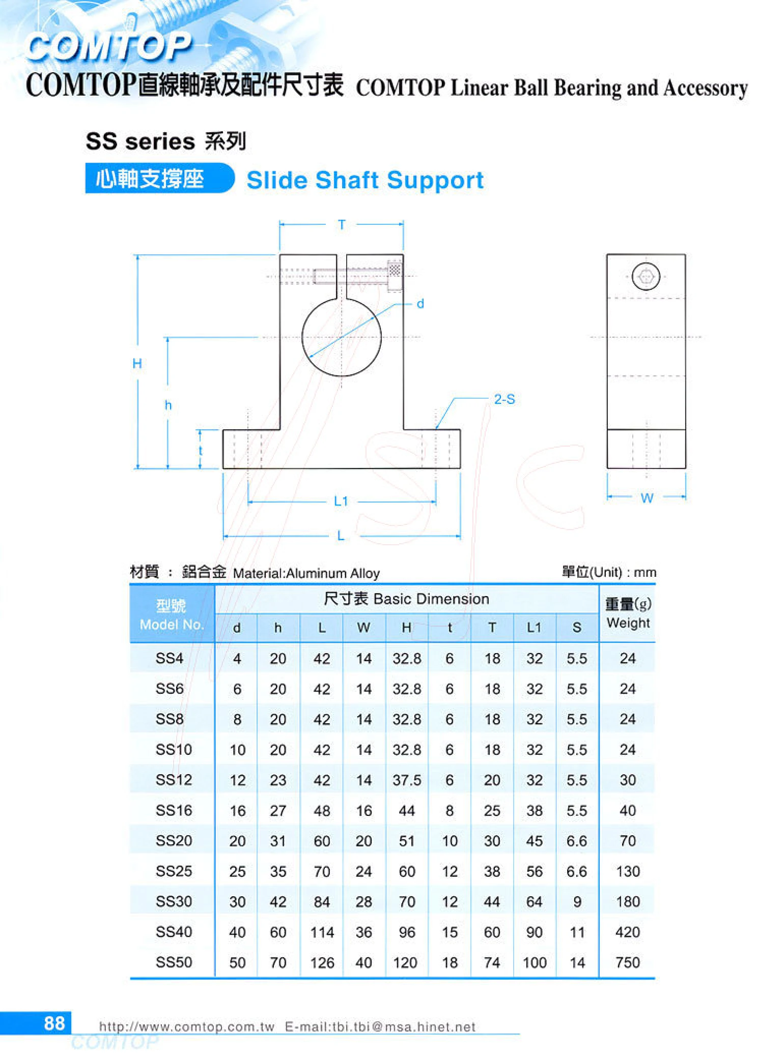
SS Series Shaft Supports
SS series shaft supports (slide shaft supports) locate and support the ends of sliding or linear shafts and are commonly used for shaft-end mounting in linear motion mechanisms. Made of aluminum alloy, they are lightweight, easy to install, and compatible with shaft diameters from d4 to d50. The catalog lists 11 sizes by shaft diameter d: SS4, SS6, SS8, SS10, SS12, SS16, SS20, SS25, SS30, SS40, and SS50. Each size includes mounting and overall dimensions such as h, L, W, H, t, T, L1, and S, as well as unit weight (24g–750g). Select the model by shaft diameter, then check the available mounting space against mounting height h, base length L, and mounting hole position S.
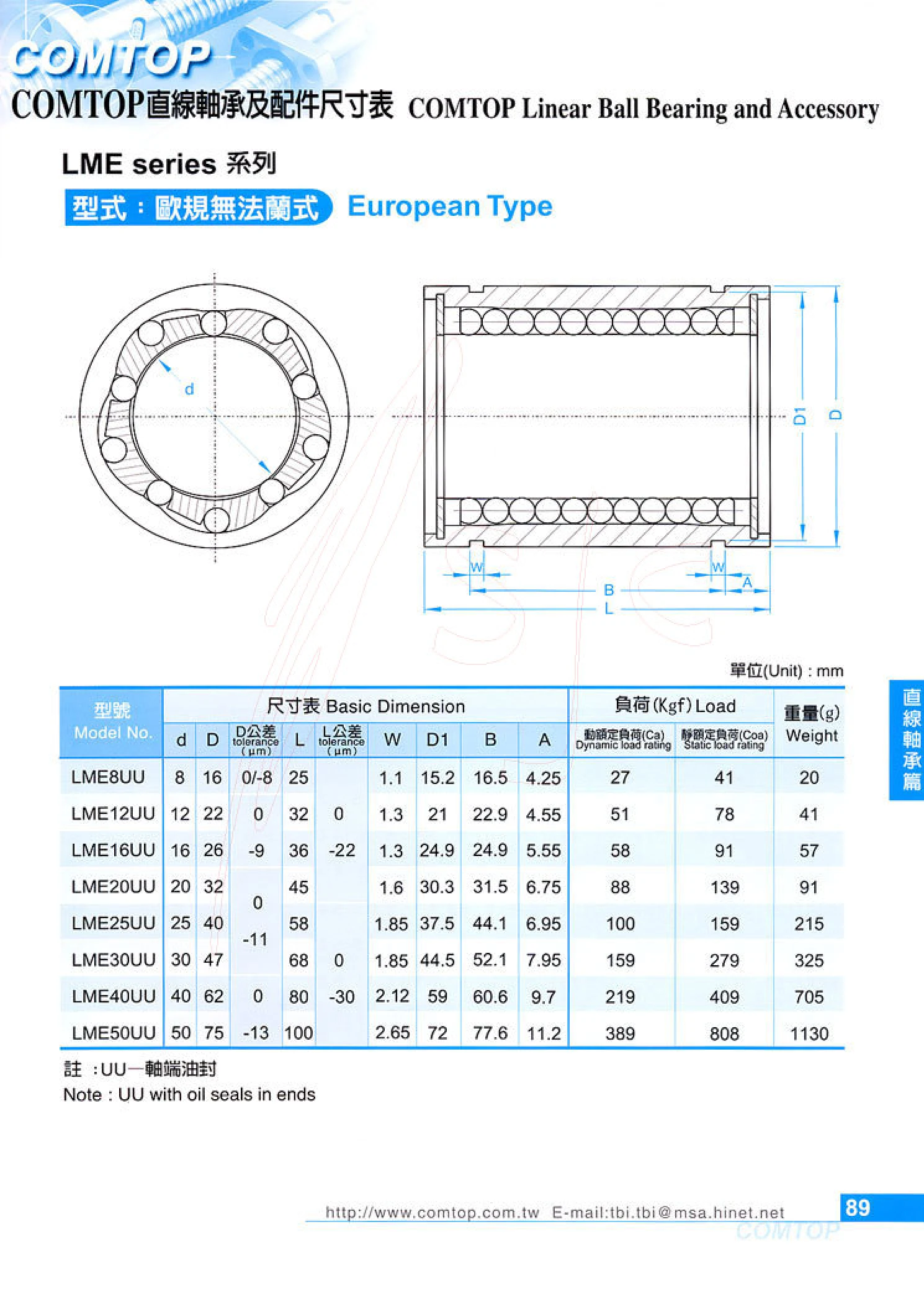
LME Series Linear Bearings (European Type)
The LME series consists of European-type linear bearings with recirculating steel balls and grooves on the outer surface. They work with cylindrical shafts to provide linear guidance and are widely used in automation equipment, machine tools, packaging machinery, printing equipment, and other applications. Model designations consist of LME + shaft diameter + UU, where UU indicates oil seals at both ends to keep out dust and retain lubrication. Specifications cover shaft diameters d 8~50 mm, outer diameters D 16~75 mm, overall lengths L 25~100 mm, basic dynamic load ratings of 27~389 kgf, static load ratings of 41~808 kgf, and unit weights of 20~1130 g. The bearings conform to internationally standardized metric dimensions and are interchangeable with European-type linear bearings of the same size. During installation, ensure proper fit tolerances and coaxial alignment between the shaft and housing bore.
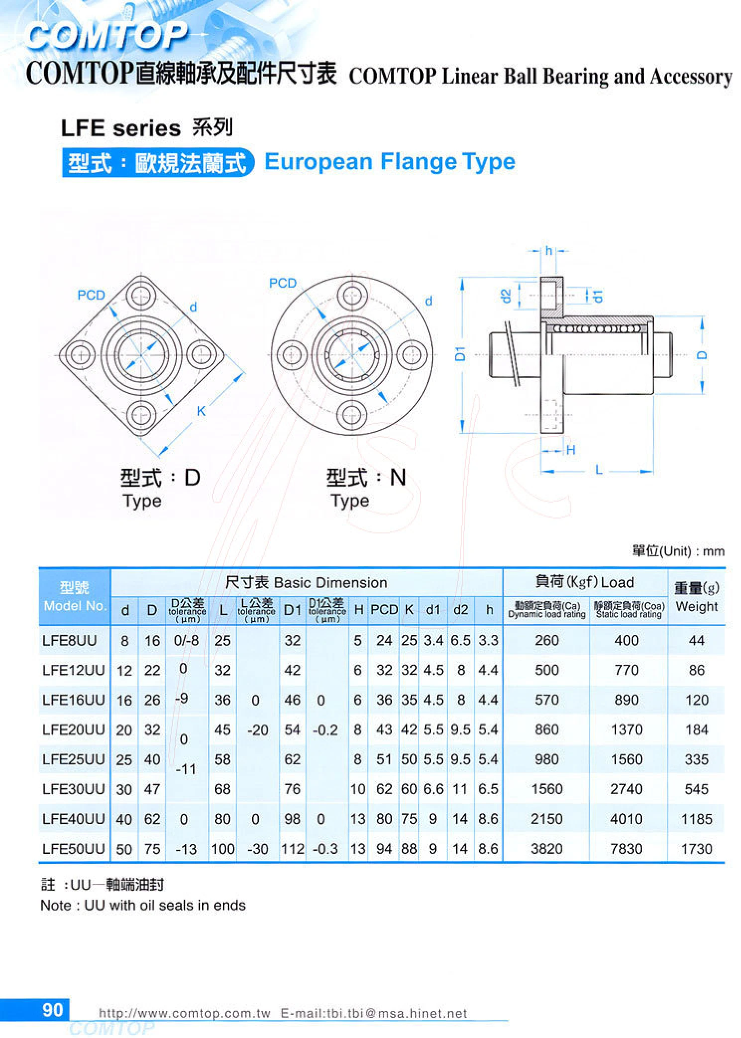
LFE Series European-Standard Flanged Linear Bearings
The LFE series consists of European-standard flanged linear bearings with a round flange for linear motion applications requiring flange mounting. The catalog covers d=8~50 mm, with models from LFE8UU to LFE50UU. UU indicates oil seals at the shaft ends. The bearings have dynamic load ratings of 260~3820 kgf, static load ratings of 400~7830 kgf, and weights of 44~1730 g. Mounting dimensions include outer diameter D, length L, flange outer diameter D1, flange thickness H, mounting hole center distances PCD and K, and mounting hole dimensions d1/d2/h, allowing easy matching with European-standard linear bearing housings or flange mounting holes.
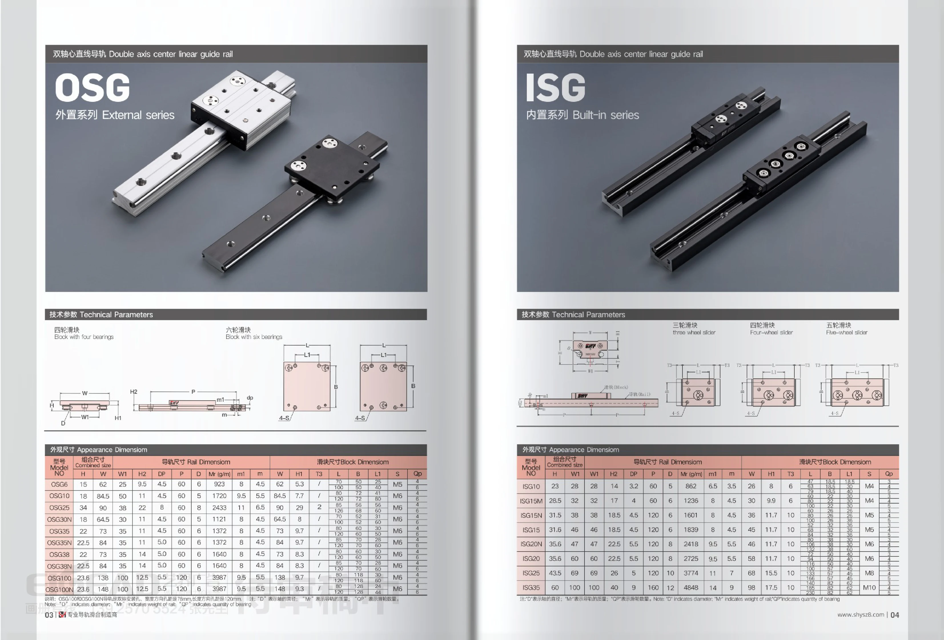
OSG/ISG Series Dual-Shaft Linear Guides
OSG/ISG series dual-shaft linear guides feature two cylindrical rails and four- or six-wheel carriages. They are available in external (OSG) and internal (ISG) series. Multiple roller bearings built into the carriage roll along the rails, providing low friction, smooth operation, high rigidity and strong load capacity. They are widely used in linear guidance and slide mechanisms for automation equipment, woodworking machinery, cutting machines and packaging machinery. The OSG series ranges from OSG6 to OSG100N, while the ISG series ranges from ISG10 to ISG35. Key specifications include combined height H, combined width W, rail width W1, rail height H2, shaft diameter D, rail pitch P, rail mass per unit length Mr (g/m), carriage width, height and length, mounting bolt size S, and roller/bearing quantity Qp. The OSG100 and OSG100N use a double oblique rail configuration, with a transverse spacing of 78mm and a longitudinal pitch of 120mm.
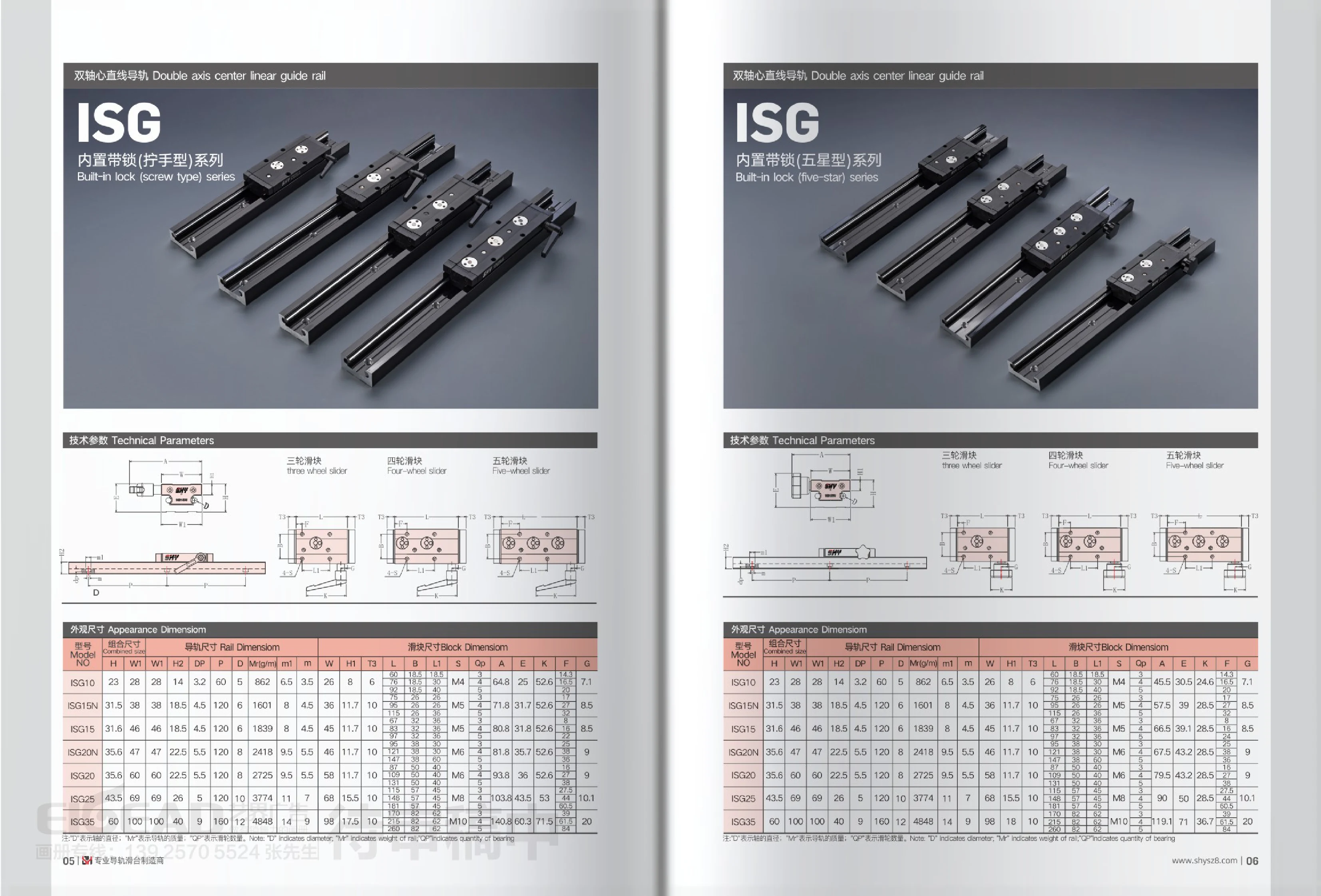
ISG Series Linear Guides
ISG series linear guides feature a four-row ball contact design for high rigidity, load capacity, and precision. Available in sizes 10, 15, 20, 25, and 35, they offer rail widths from 28mm to 100mm and assembly heights from 23mm to 60mm. Standard (N), extended, and other block types accommodate a range of travel and load requirements. Applications include automated equipment, CNC machine tools, and precision measuring instruments.
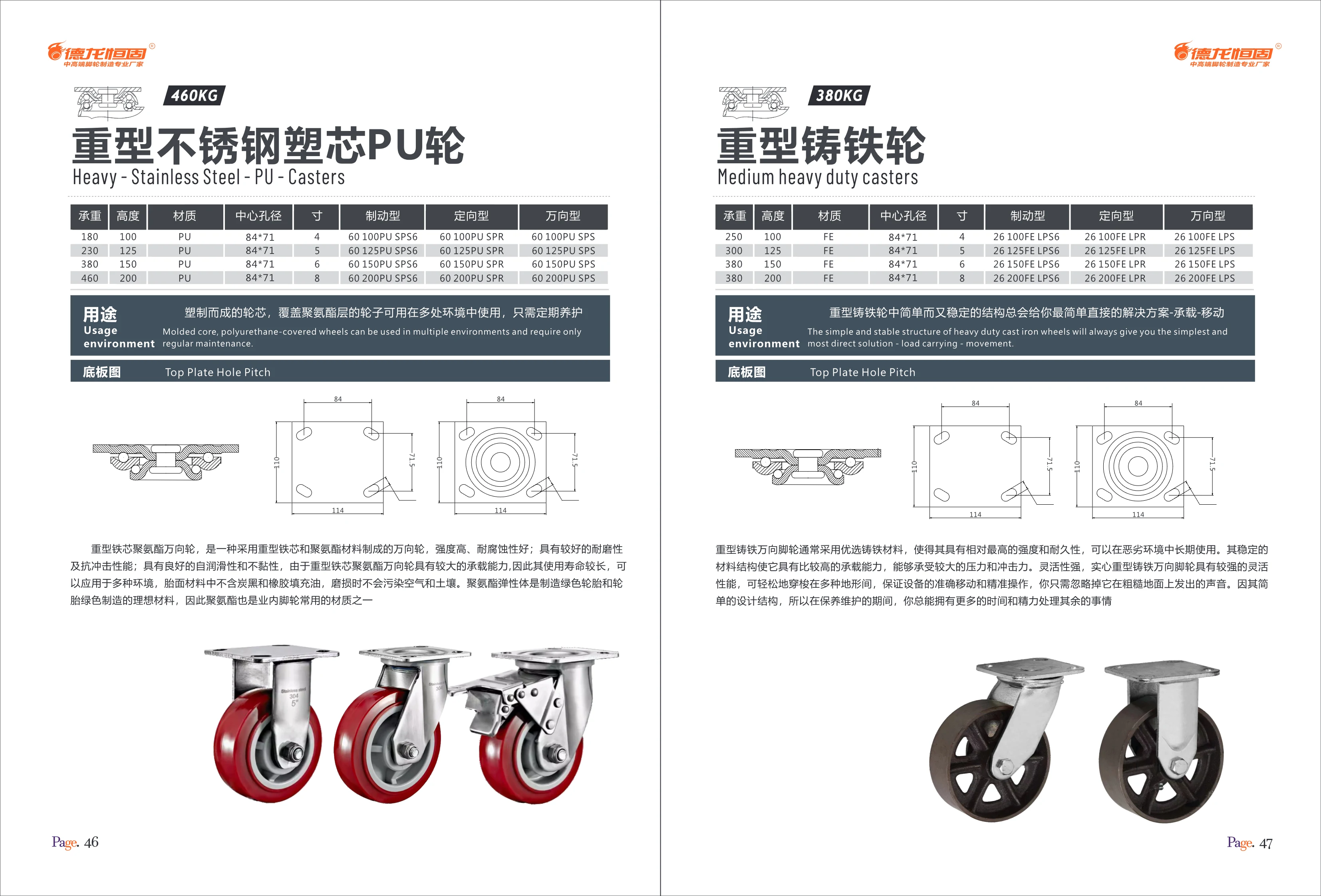
Heavy-Duty Stainless Steel Casters with Plastic-Core PU Wheels
These wheels feature a plastic core covered with a polyurethane layer and are suitable for a wide range of environments with only periodic maintenance. This series of heavy-duty stainless steel casters with plastic-core PU wheels has a load capacity of 180–460 kg, a height of 100–200 mm, and a mounting-hole spacing of 84 × 71 mm. Available in 4-, 5-, 6-, and 8-inch sizes, they come in three types: braked, fixed, and swivel, to meet different mobility needs. They offer high strength, corrosion resistance, wear resistance, and impact resistance for a long service life.
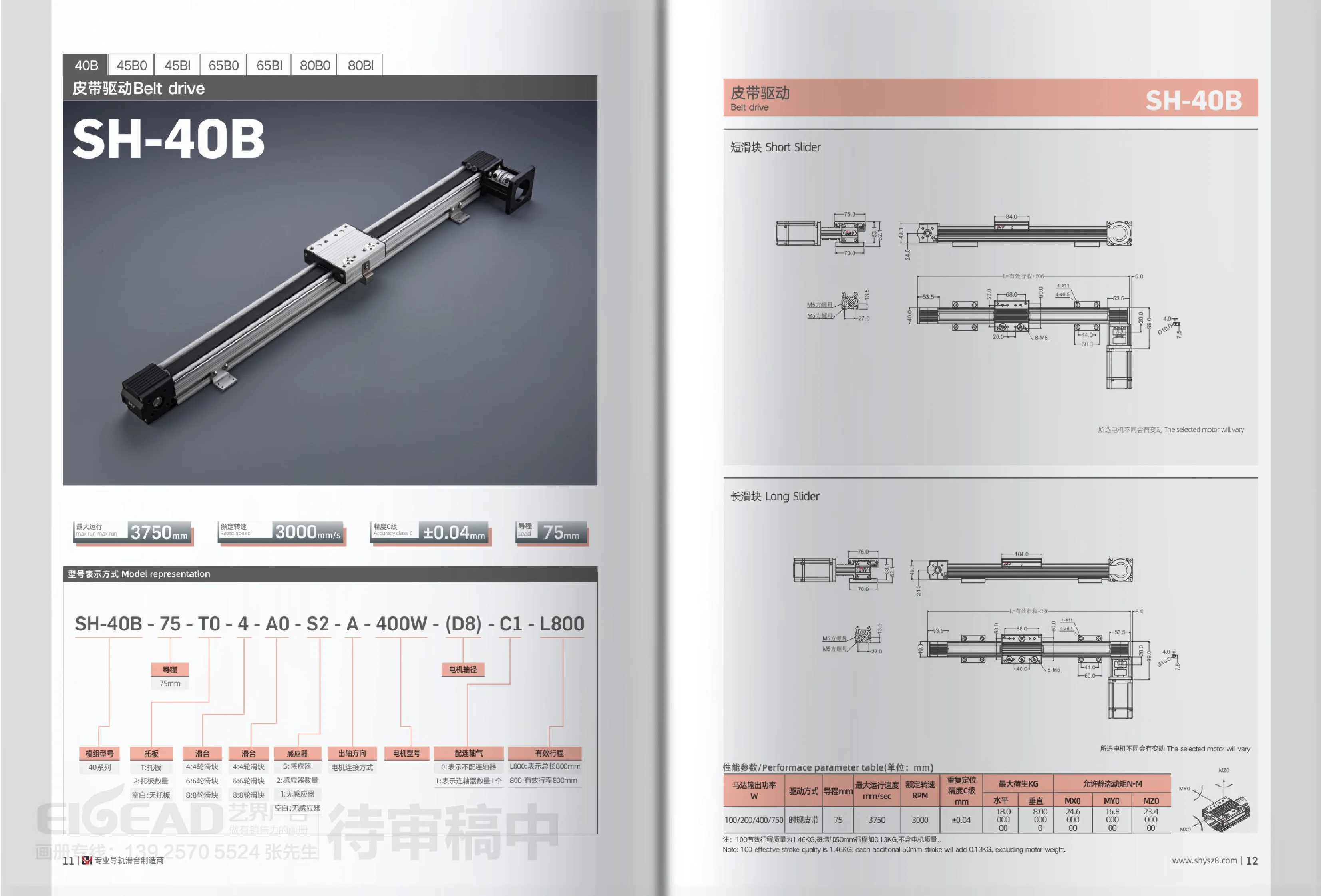
SH-B Series Belt-Driven Linear Modules
The SH-B series comprises timing belt-driven linear modules available in 40B, 45B0/45BI, 65B0/65BI, and 80B0/80BI models. The SH-40B, for example, has a 75mm lead, a maximum operating speed of 3750mm/s, a rated speed of 3000rpm, and Class C repeatability of ±0.04mm. Motor power options are 100/200/400/750W. Maximum load capacity is 18.0kg horizontally and 8.0kg vertically, with allowable static torques of MXD 24.5N·m and MYO 16.8N·m. The model designation includes the main model, lead, carriage plate, slider, sensor, motor connection, motor model, power, shaft diameter, coupling, and length, allowing selection by stroke length and accessory combination. The unit weighs approximately 1.46kg with a 100mm effective stroke, with an additional 0.13kg for every 50mm of stroke. Motor weight is excluded.
SH Series Belt-Driven Linear Modules
SH series belt-driven linear modules feature a timing (synchronous) belt drive and an extruded aluminum body. They are available in a wide range of travel lengths and cross-section sizes, including 40B, 45B0, 45BI, 65B0, 65BI, 80B0 and 80BI. For example, the 40 series has a lead of 75mm, a maximum speed of 3750mm/s, a rated speed of 3000RPM, and Class C repeatability of ±0.04mm. Its maximum load is 18.0kg horizontally and 8.00kg vertically, with allowable static torques of MXD 24.5N·m and MYO 16.8N·m. It can be fitted with 100/200/400/750W motors. The module weighs approximately 1.46kg at 100mm effective travel, with an additional 0.13kg for every 50mm of travel (excluding the motor). The model number combines codes for the module series, lead, carriage plate, number of carriage wheels, motor mounting configuration, sensor, motor model, motor power, motor shaft diameter, accuracy class, and overall length/effective travel.
Heavy-Duty Cast Iron Casters
Heavy-duty cast iron casters (medium-duty casters) are made from carefully selected cast iron, offering high strength and durability for long-term use in harsh environments. Their stable construction provides a high load capacity and withstands substantial pressure and impact. Highly maneuverable, they move easily across a variety of surfaces to ensure precise equipment movement and operation. Their simple design also makes maintenance easier. Available in braked, rigid, and swivel configurations, with load capacities of 250–380 kg, wheel diameters of 4–8 inches, and overall heights of 100–200 mm. Suitable for industrial material handling, warehousing, logistics, and more.
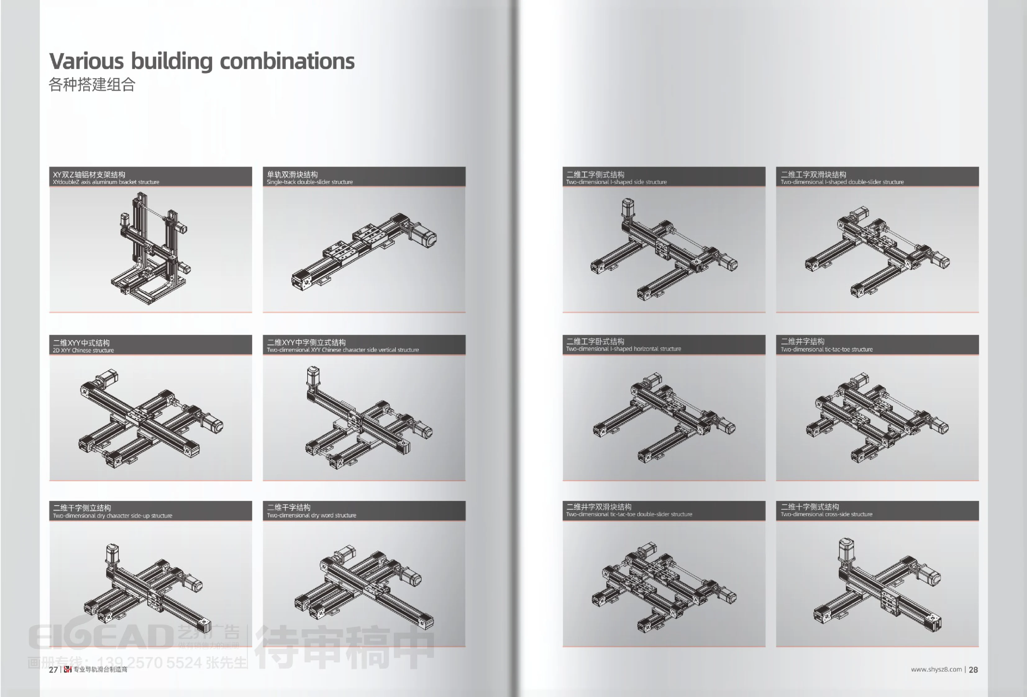
XY Multi-Axis Linear Stage Assemblies
XY multi-axis linear stage assemblies combine two or more linear stages in different spatial orientations to create a motion platform capable of two-dimensional movement along the X and Y axes, or three-dimensional movement with the addition of a Z axis. This series is categorized by configuration rather than by individual model. Options include an XY dual-Z-axis assembly with an aluminum support frame, a single-rail dual-carriage assembly, two-dimensional XY 中-shaped and side-mounted 中-shaped assemblies, two-dimensional 千-shaped and side-mounted 千-shaped assemblies, side-mounted, dual-carriage and horizontal 工-shaped assemblies, and two-dimensional 井-shaped and dual-carriage 井-shaped assemblies. Depending on travel, load direction, installation space and accuracy requirements, users can select a single-rail dual-carriage configuration for greater resistance to overturning, or a symmetrical 工-shaped or 井-shaped configuration to distribute off-center loads. These assemblies are commonly used for handling, positioning, dispensing and screw fastening in custom automation equipment. They can be paired with stepper motors, servo motors and various controllers, with cross-sectional dimensions and travel customized to the application.
Cleanroom Cable Carrier
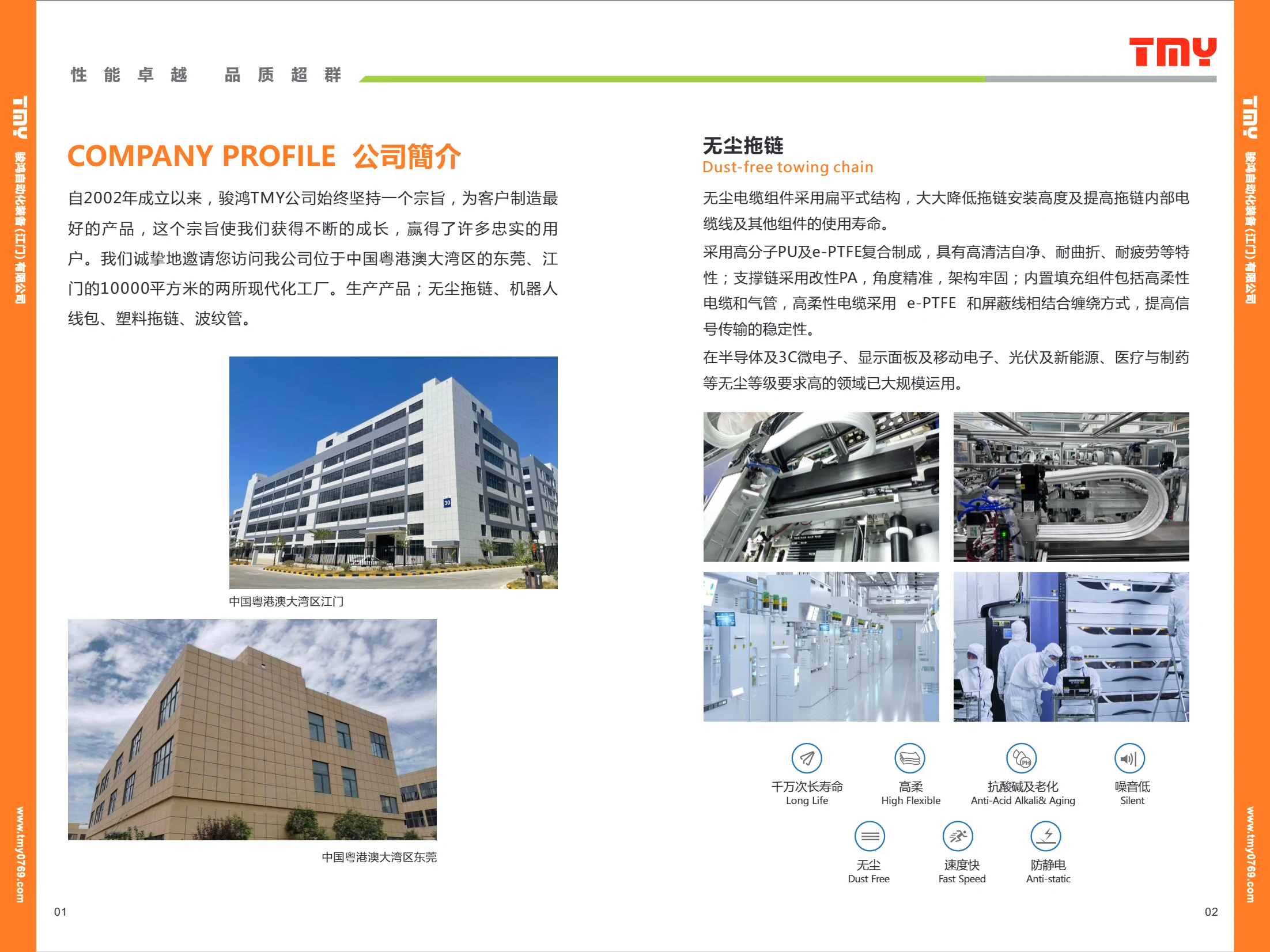
The cleanroom cable carrier features a flat design that reduces installation height while protecting the cables and air tubes inside. Its sheath is made from a polymer PU and e-PTFE composite, offering high cleanliness, self-cleaning properties, flex and fatigue resistance, antistatic performance, low noise, and a long service life of tens of millions of cycles. The support chain is made from modified PA for precise angles and a robust structure. It houses highly flexible cables and air tubes, with the cables wrapped using e-PTFE and shielding to improve signal transmission stability. It is suitable for high-cleanliness applications in semiconductors, 3C microelectronics, display panels, mobile electronics, photovoltaics and new energy, medical devices, and pharmaceuticals. Sheath configurations include 1P, 2P, 3P, 4P, and special three-hole/five-hole versions. The sheath is 1.4mm thick, with an internal opening width of 20.5/29mm and an overall width of 39~138mm.
Robot Dress Packs
Robot dress packs, also known as robot cable and hose packs or robot harness packs, are one of the product lines manufactured by Junhong TMY, alongside cleanroom cable carriers, plastic cable carriers, and corrugated tubing. They route and protect cables and pneumatic hoses along industrial robot bodies and joints, allowing cables to remain highly flexible and resistant to torsion and fatigue during multi-axis movement, reducing wear and downtime. Common specifications include compatible robot models and number of axes, cable cross-sectional area and core count, bend radius, protection rating, and operating temperature range.
Cleanroom Cable Carrier
A cleanroom cable carrier is a flat cable carrier designed for highly controlled environments. It reduces installation height and extends the service life of internal cables and components. Made from a polymer PU and e-PTFE composite, it offers self-cleaning, flex and fatigue resistance, resistance to acids, alkalis and aging, low noise, and antistatic properties. The support chain is made from modified PA for precise angles and a robust structure. It houses highly flexible cables and pneumatic tubing, with cables wrapped using a combination of e-PTFE and shielding wire to improve signal transmission stability. It is suitable for industries with stringent cleanliness requirements, including semiconductors, 3C microelectronics, display panels, mobile electronics, photovoltaic energy, medical devices, and pharmaceuticals.