product — Page 72
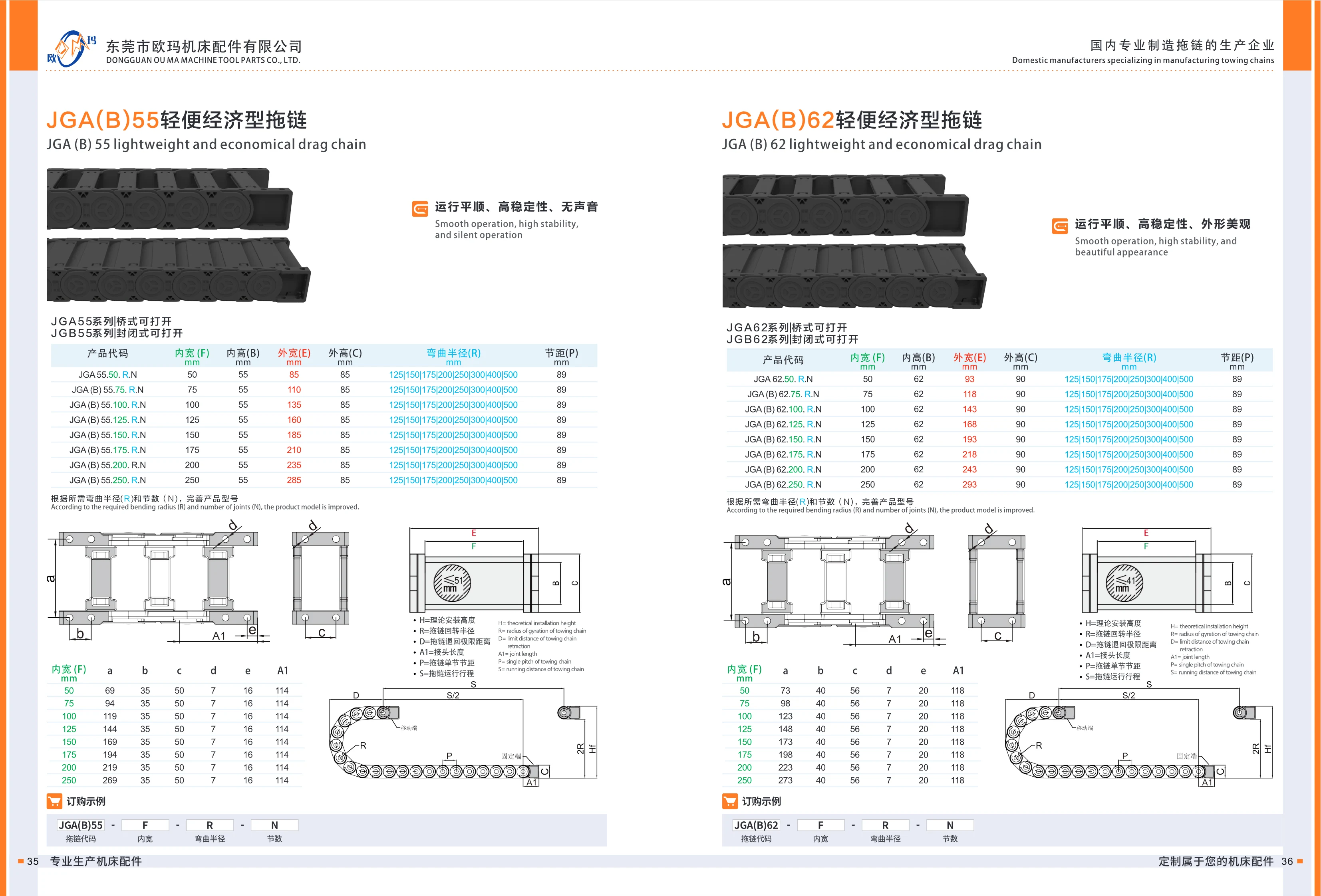
JGA(B)62 Lightweight Economy Cable Carrier
The JGA(B)62 lightweight economy cable carrier is available in two designs: the JGA62 series with an openable bridge-style construction and the JGB62 series with an openable enclosed construction. It protects and guides cables and oil hoses in machine tools and automated equipment. Inner width: 50mm; inner height: 62mm; outer width: 93mm; outer height: 90mm. Available bend radii include 125, 150, 175, 200, 250, 300, 400 and 500mm (refer to the specification table for details). The product code format is JGA62.50.R.N, where R is the bend radius and N is the number of links. The carrier can be customized to suit the required travel distance and installation space. Made of reinforced nylon, it is lightweight, economical, wear-resistant and quiet.
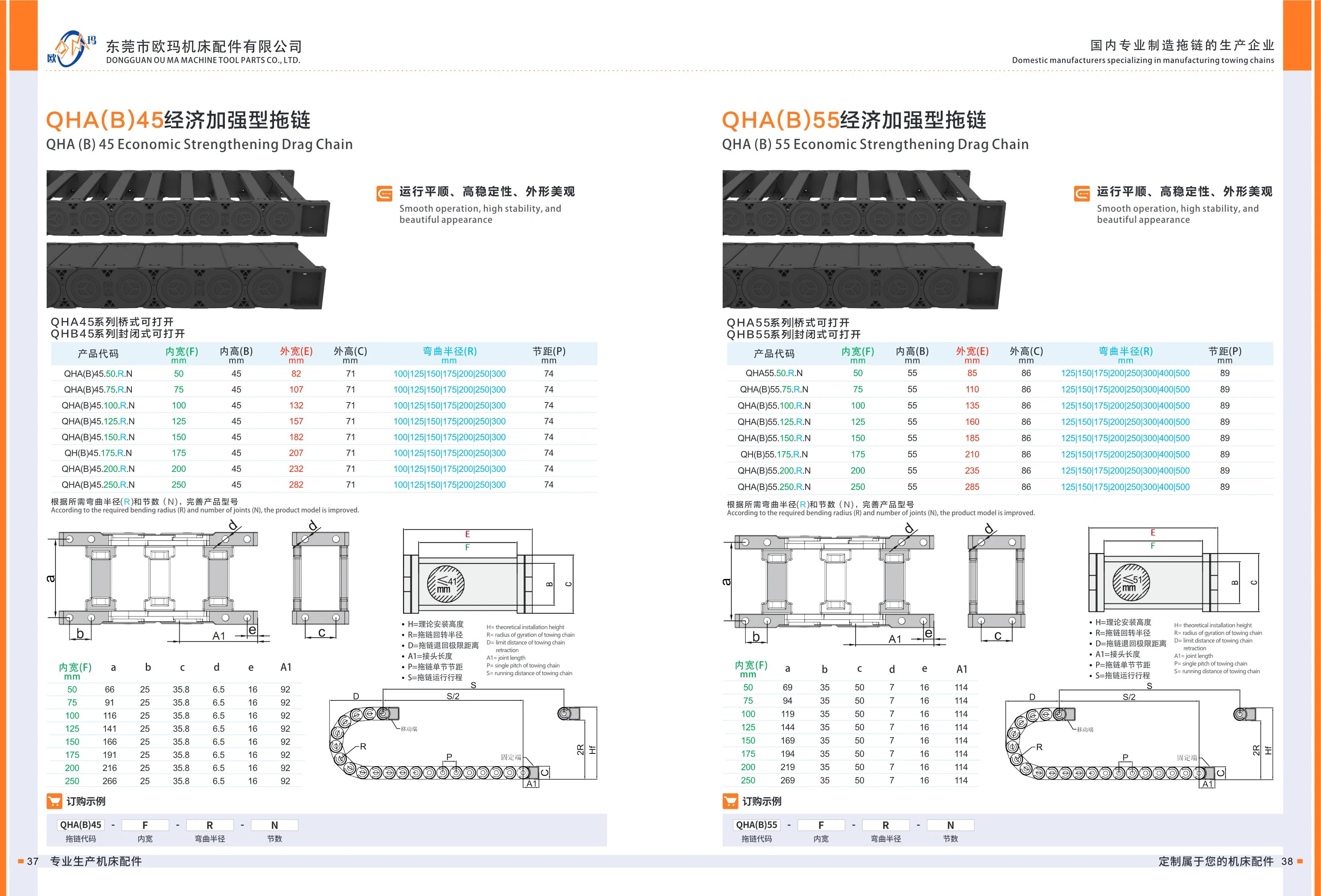
QHA(B)45 Series Economical Reinforced Cable Chains
The QHA(B)45 series consists of economical reinforced plastic cable chains that offer smooth operation, high stability and an attractive appearance. They guide and protect cables and hoses in machine tools and automated equipment. The series is available in two designs: the QHA45 series has an openable bridge-type structure for quick cable installation and maintenance, while the QHB45 series has an openable enclosed structure for greater protection against dust and chips. The series has an inner width (F) of 50 mm, inner height (B) of 45 mm, outer height (C) of 82 mm and pitch (P) of 100 mm. Bending radius (R) options include 71, 100, 125, 150, 175, 200, 250, 300, 350 and up to 5000 mm. Orders are configured using the required bending radius and number of links N. The model format is QHA(B)45.inner width.bending radius.number of links.
QHA(B)55 Economy Reinforced Cable Carrier
The QHA(B)55 economy reinforced cable carrier is available in two designs: the openable QHA55 open-frame type and the openable QHB55 enclosed type. Both protect moving cables on machine tools, automated equipment and similar machinery. The carrier operates smoothly, offers high stability and has an attractive appearance. It has an inner height of 55 mm, an outer height of 86 mm, inner widths of 50, 75, 100, 125, 150, 175, 200 and 250 mm, bend radius options of 125, 150, 175, 200, 250, 300, 400 and 500 mm, and a pitch of 89 mm. When ordering, complete the product model with the required bend radius (R) and number of links (N).
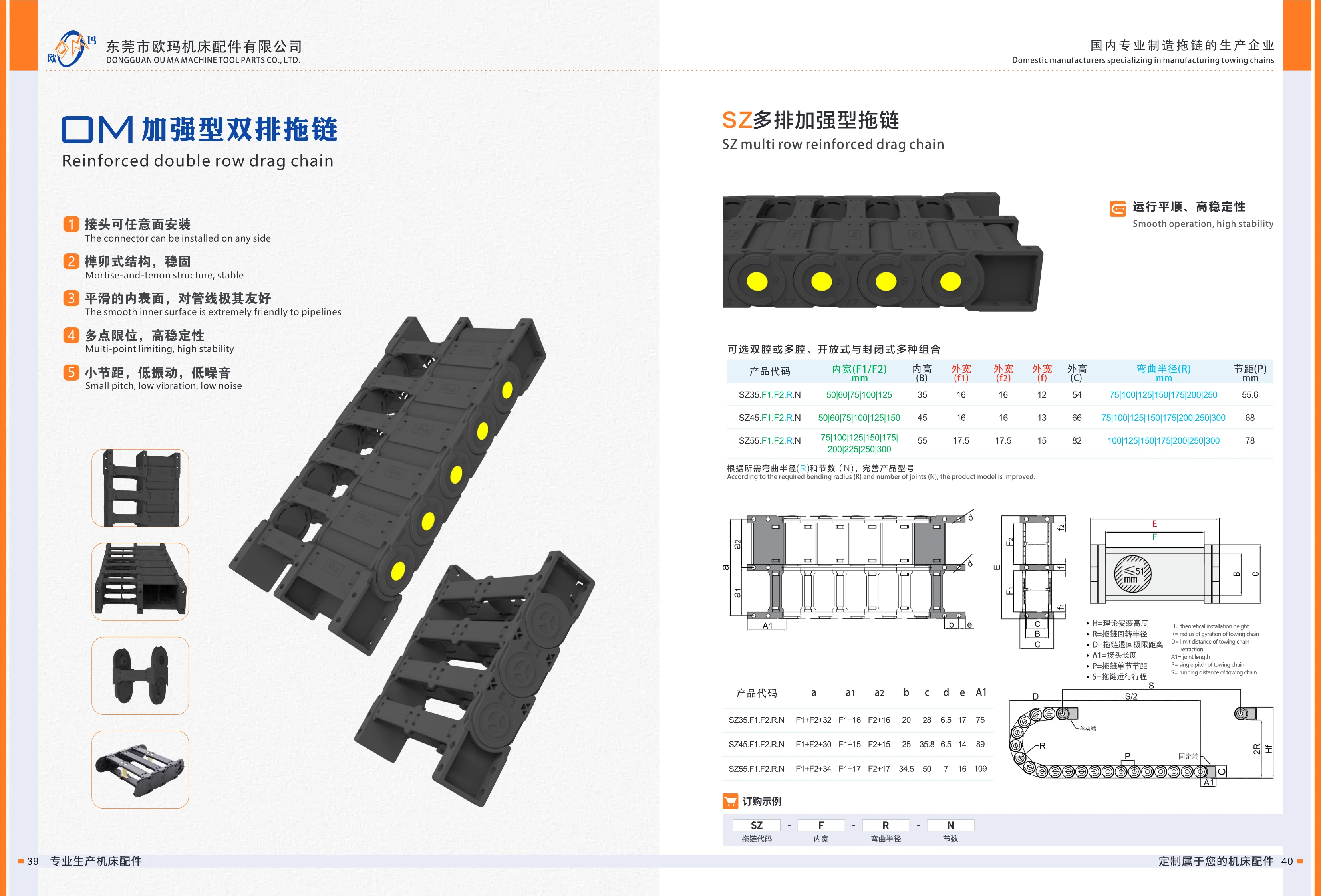
SZ Series Reinforced Multi-Row Cable Carriers
SZ Series reinforced multi-row cable carriers protect cables, hydraulic hoses, pneumatic tubes and other lines in machine tools and automation equipment. Their wedge-and-tenon construction provides a stable assembly, with mounting brackets that can be installed on any face. Smooth interior surfaces minimize friction on the lines, while multiple stop points ensure smooth, stable operation. A short pitch reduces vibration and noise. Available in two-compartment or multi-compartment configurations, with open or enclosed designs, the range includes SZ35, SZ45 and SZ55 models in various internal widths and heights, external widths and heights, and bend radii. They are suitable for reciprocating applications requiring segregated routing across multiple rows and compartments.
SZ Series Reinforced Double-Row Cable Carrier
The reinforced double-row cable carrier (SZ multi-row reinforced cable carrier) guides and protects cables, oil hoses, and pneumatic lines on machine tools and automated equipment. Its wedge-and-tenon construction allows connectors to be installed on any side for flexible assembly and disassembly and a secure fit. The smooth interior minimizes wear on cables and hoses, while a multi-point stop design ensures stability during high-speed reciprocating motion. The short pitch enables smooth operation with low vibration and noise. Double- or multi-compartment configurations and open or enclosed designs are available to accommodate different numbers of cables and hoses and protection requirements. Key dimensions include inner width (F1/F2), inner height (B), outer width (f1/f2), outer height (C), bend radius (R), and pitch (P). The main models are SZ35, SZ45, and SZ55, representing three cross-sectional sizes. Their model codes are completed using options such as inner width, bend radius, and pitch. Select a size based on the outer diameter of the cables and hoses and the available installation space.

SJ Economy Double-Row Cable Carrier
The SJ economy double-row cable carrier protects cables with a double-row design, offering a choice of two or multiple compartments across its width and various open and enclosed configurations. It guides and protects cables, oil hoses and pneumatic lines on machine tools, automation equipment and other moving mechanisms. The series comes in four sizes based on inner height: SJ35, SJ45, SJ55 and SJ62, with inner heights of 35, 45, 55 and 62mm, respectively. Inner widths (F1/F2) are available in multiple options from 50~300mm; outer widths (f1) are 14.5, 16, 17.5 and 21.5mm, respectively; pitches (P) are 56, 68, 89 and 89mm, respectively; and bending radii (R) are available in multiple options from 75~500mm. When ordering, combine the carrier code SJ with the inner width F, bending radius R and number of links N to form the complete model designation. Calculate the number of links based on the actual travel and bending radius. The series is a low-cost, general-purpose double-row cable carrier solution.
SJ Economy Double-Row Cable Carrier
The SJ economy double-row cable carrier features a double-row compartment design, with two- or multi-compartment configurations and open or enclosed options. It protects and guides cables on machine tools and automated equipment. Four sizes are available by inner height: SJ35, SJ45, SJ55 and SJ62. Inner widths (F1/F2) range from 50~300mm, bending radii R from 75~500mm, and pitches from 56~89mm. Users can complete the model designation using the required bending radius (R) and number of links (N). The ordering code follows the format SJ35.F1.F2.R.N. The carrier is economical, practical, smooth-running and easy to install.

HGA Series Sliding Cable Carrier
The HGA series sliding cable carrier features an openable bridge-style design, smooth operation, high stability, and an attractive appearance. It is primarily used to protect and guide cables, oil hoses, and pneumatic lines in machine tools and automated equipment. Two sizes are available by inner height: HGA35 (inner height 35mm) and HGA45 (inner height 45mm). Inner width F ranges from 50~300mm, and bend radius R ranges from 75~300mm. The outer height is 55.5mm for HGA35 and 66mm for HGA45. The complete model designation consists of four parts: cable carrier code, inner width, bend radius, and number of links. Specify the required bend radius and number of links to complete the model designation. The openable design simplifies cable installation and routine maintenance, making it suitable for applications with frequent reciprocating motion.

WQ Series Multidirectional Cable Chains
WQ series multidirectional cable chains are injection-molded from engineering plastic. Their covers and crossbars can be opened for easy cable installation and maintenance. A mortise-and-tenon mounting structure provides secure link connections, while smooth interior surfaces minimize wear on cables and hoses. The short-pitch design reduces vibration and noise during operation, making the chains suitable for high-speed reciprocating motion. Optional integrated strain-relief connectors reduce stress at cable ends. Models range from WQ(F)40 to WQ(F)100, with A dimensions of 17.8~38 mm, pitches of 14~34.5 mm, and bending radii of 58~145 mm. Select a model based on available equipment space and cable outer diameter.
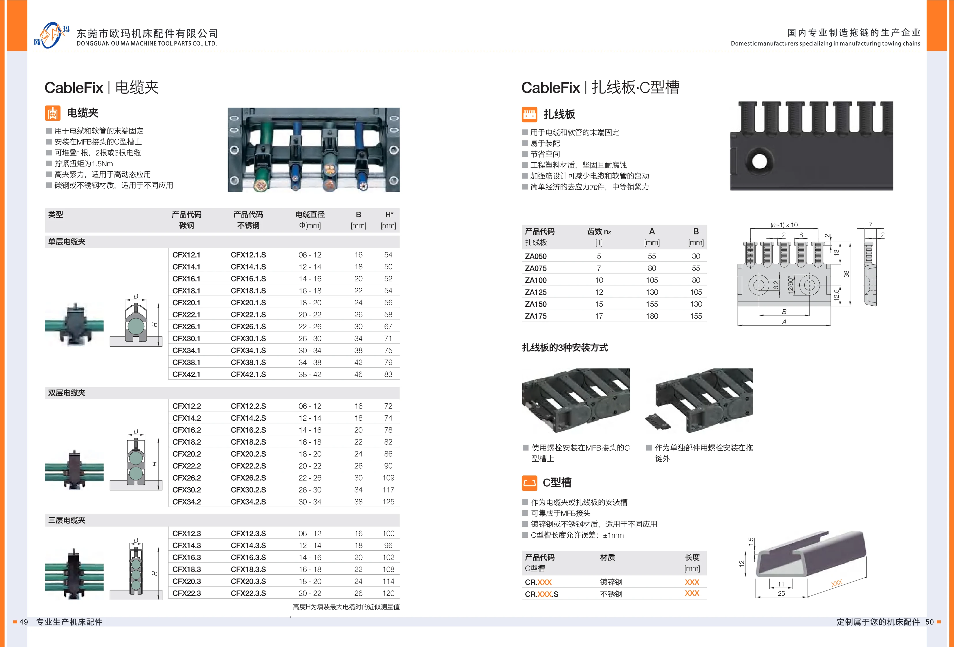
CableFix CFX Series Cable Clamps
CableFix CFX series cable clamps secure the ends of cables and hoses. They can be mounted on the C-slot of an MFB connector or used with accessories such as cable tie plates. Available in carbon steel or stainless steel for different operating conditions, their stackable design secures 1, 2, or 3 cables. With a tightening torque of 1.5N·m and high clamping force, they are suitable for highly dynamic applications. Sizes range from Φ6-12 to Φ38-42 mm by cable outer diameter. Single-, double-, and triple-layer models are designated CFXxx.1, CFXxx.2, and CFXxx.3, respectively; stainless steel models have .S appended to the code. When selecting a clamp, consider the cable diameter, B width, and H height. H is the approximate height when the largest cable is installed.
ZA Series Cable Tie Plates
The ZA series cable tie plate is a robust, corrosion-resistant engineering plastic accessory for securing cable and hose ends. Its reinforced rib design helps reduce cable and hose movement, providing a simple, economical strain relief solution with medium holding force. The product supports three mounting methods: it can be bolted to the C-slot of an MFB connector or mounted separately outside the cable carrier. The series includes 6 sizes, from ZA050 to ZA175, with 5 to 17 teeth, dimension A from 55 to 180 mm, and dimension B from 30 to 155 mm, accommodating a range of cable bundle securing requirements.
CR Series C-Channel
The CR series C-channel is a universal mounting channel for cable clamps and cable tie plates. It can be integrated into MFB connectors to secure cable and hose ends and manage their routing. Available in galvanized steel and stainless steel, the channel meets a range of operating conditions and corrosion resistance requirements. Products are made to length and designated CR.XXX (galvanized steel) or CR.XXX.S (stainless steel), where XXX represents the channel length in mm, with a length tolerance of ±1mm. Cable clamps or cable tie plates can be bolted into the channel for compact, straightforward assembly. It provides a reliable, economical mounting base for cable management and strain relief components.

TL Series Steel Cable Carriers
TL series steel cable carriers consist of chrome-plated high-quality steel link plates, extruded aluminum alloy support plates, and alloy steel pins. Their triple-reinforced construction provides excellent resistance to deformation. During operation, they prevent cables and hoses from moving relative to the carrier or becoming twisted. They bend easily, with low resistance and noise, and resist deformation and sagging over long-term use. The chrome-plated link plates offer an attractive metallic finish and corrosion resistance. The maximum travel speed is 40 m/min, with a noise sound pressure level of no more than 68 dB at maximum speed. The safe service life is at least 1 million reciprocating cycles. The carriers meet export certification requirements such as CE/UL and can accommodate approximately 99% of CNC machine tool applications. Models range from TL45 to TL250, with pitches of 45–250 mm and inner widths of 50–1000 mm. Support plates are available in types I, II, III, and fully enclosed versions. Orders can be specified by bend radius, inner width, and outer width.
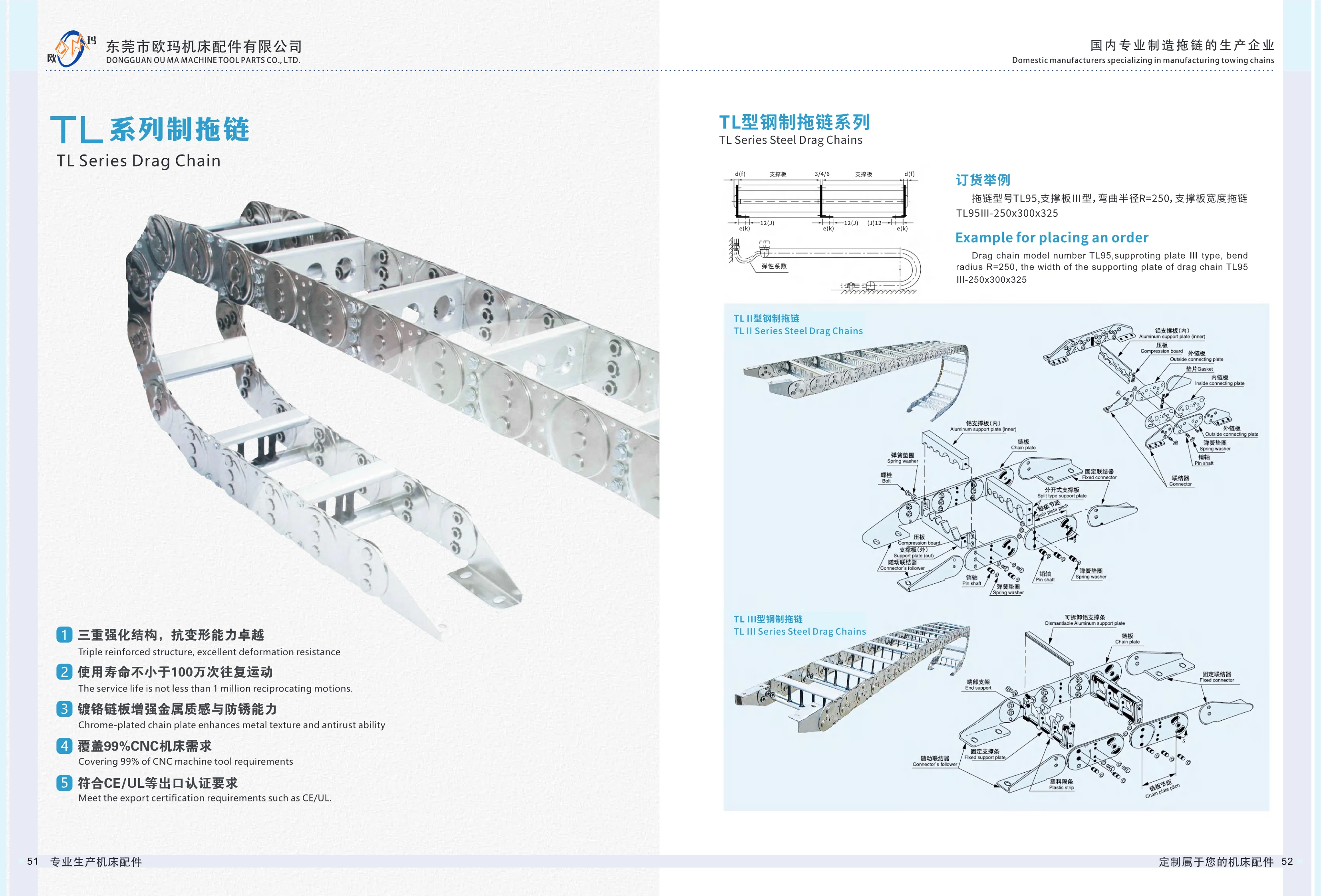
TL Type III Steel Cable Carrier
TL series steel cable carriers feature a triple-reinforced structure with excellent resistance to deformation. They guide and protect cables, oil hoses, and air hoses on CNC machine tools and other equipment. The chrome-plated side plates provide a metallic finish and corrosion resistance. With a service life of at least 1 million reciprocating cycles, the carriers meet 99% of CNC machine tool cable routing needs and comply with export certification requirements such as CE and UL. They are available with Type I, II, or III support plates; Type III is designed for heavier, thicker cables. When ordering, specify the carrier model (e.g., TL95), support plate type (III), bend radius R (e.g., 250), and support plate width dimensions, in that order. The catalog provides the following ordering example: TL95III-250x300x325.

TLGA Series Steel Cable Carrier
TLGA series steel cable carriers are designed for machine tools, mobile machinery and other equipment to carry large numbers of heavy cables and oil hoses. They can achieve long unsupported spans without support rollers. Support plates can be customized to customer requirements, with chain plate heights of 35-150mm and support plate widths of 150-600mm available as needed. The spacing between holes is 5mm, the bending radius is 50-600mm, and the maximum travel is 32m. The carrier can be lengthened or shortened as required, and its bending radius can be adjusted by changing the pivot pins. When selecting a model, the chain plate height is determined by the largest cable diameter. For widths over 300mm and lengths over 4m, selecting the next larger size is recommended for stability.
TL/TLGA Series Steel Cable Carriers
TL/TLGA series steel cable carriers support cables, oil lines, and pneumatic and hydraulic hoses in reciprocating applications such as machine tools and mobile machinery. The TLGA model can carry a large number of heavy lines over a long unsupported span, with support plates made to order. Bending radius: 50-600 mm; chain plate height: 35-150 mm; maximum travel: 32 m; support plate width: 150-600 mm; hole spacing: 5 mm. Support plates are available in one-piece, split, and frame styles, selected according to line load, connector size, and installation, removal, and maintenance requirements. Wide carriers can be fitted with a third chain plate to improve stability and separate conduits from cables.
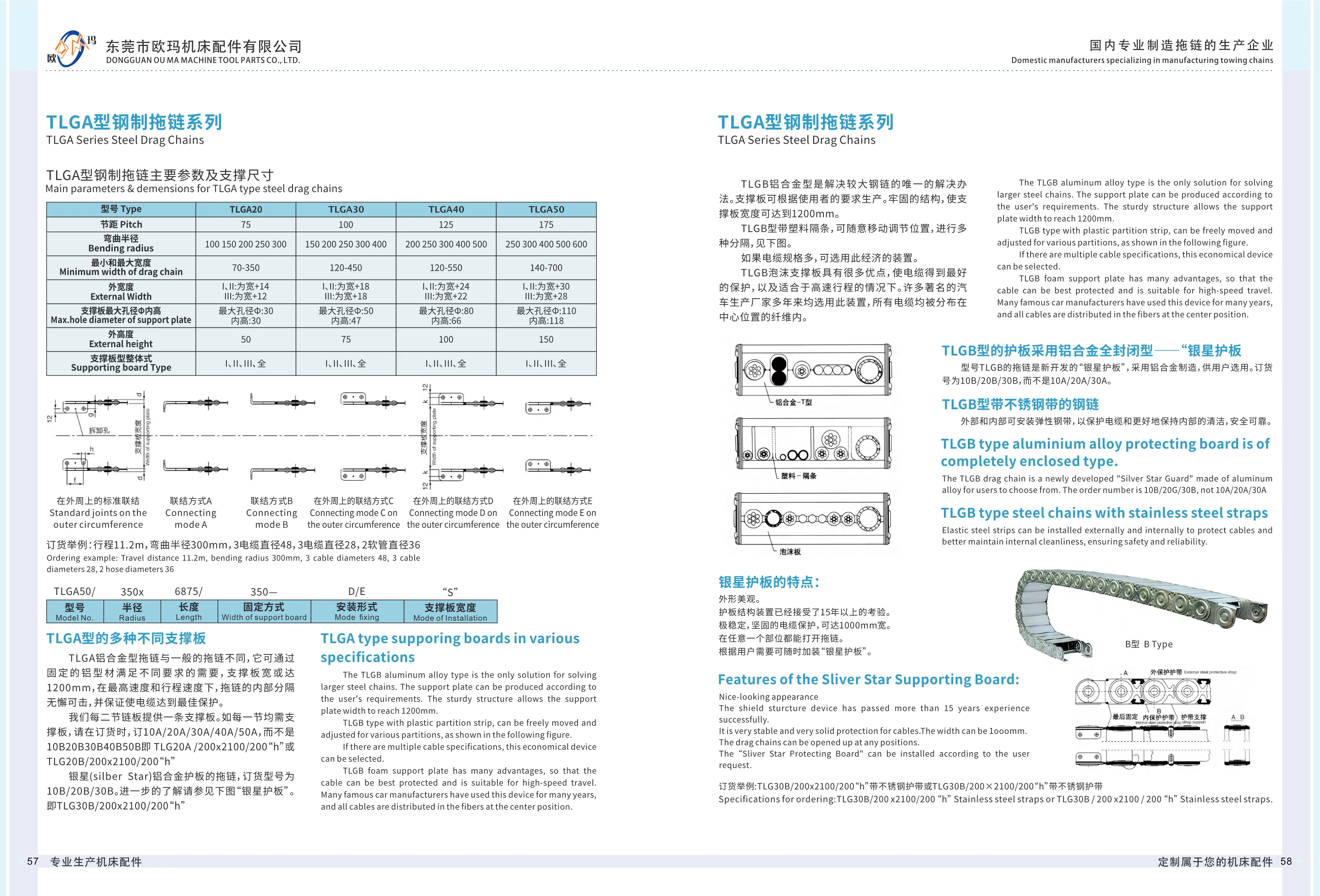
TLGA Series Steel Cable Carriers
TLGA series steel cable carriers guide and protect cables and hoses in machine tools and automation equipment. Their steel links and adjustable support plates make them suitable for high-speed, long-travel applications. The main models are TLGA20, TLGA30, TLGA40 and TLGA50, with pitches of 75, 100, 125 and 175 mm respectively. Bending radii range from 100~700 mm, carrier widths from 70~700 mm, and maximum support plate hole diameters from 30~110 mm; the internal height is 30 mm. Support plate styles include I, II, III and full type. Depending on the style, the external width is 12~30 mm greater than the carrier width. Orders can be specified by travel length, bending radius, cable/hose diameter and mounting configuration. Ordering example: TLGA50/350x6875/350-D/E“S”.
TLGB Series Aluminum Alloy Cable Carriers
The TLGB series aluminum alloy cable carrier features support plates made from aluminum alloy profiles, providing a robust solution for applications requiring large steel cable carriers. The support plates can be custom-made to customer specifications, with a maximum width of 1200mm. Plastic dividers are supplied as standard and can be freely repositioned to create various internal compartments, offering an economical and practical solution for applications involving cables of different sizes. A foam support plate option is also available for optimal cable protection in high-speed travel applications. Long used by many automotive manufacturers, this design positions all cables within centrally located fibers. A stainless steel strip option is also available, with flexible steel strips mounted on the outside and inside to protect cables and keep the interior clean. These safe, reliable carriers are widely used to protect cables and hoses in machine tools, automotive production lines, and automated equipment.
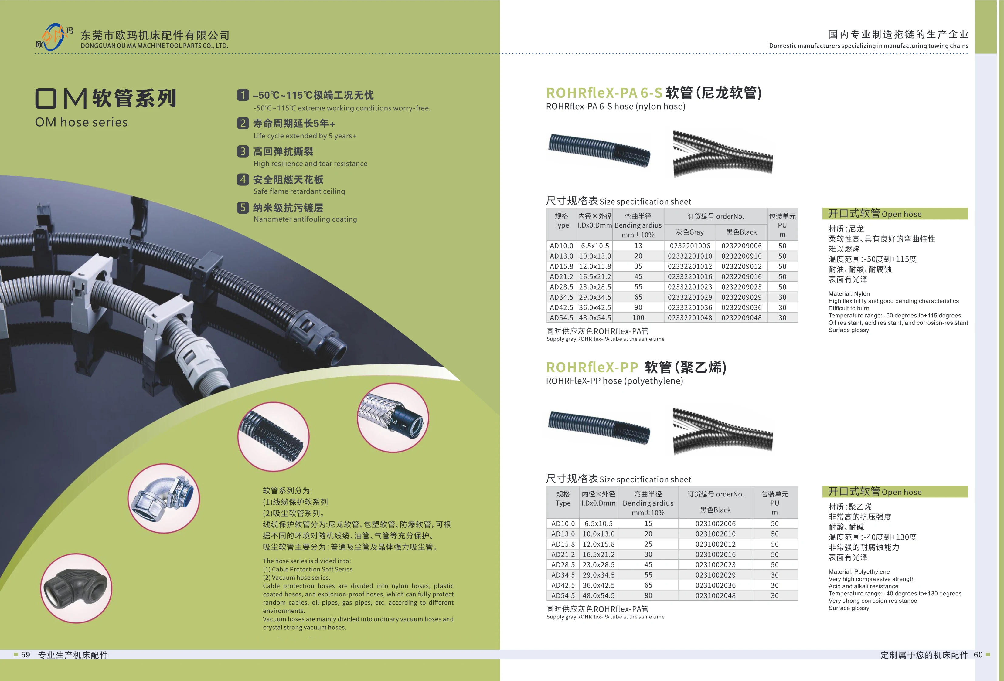
M Series Conduits
M Series conduits protect cables in factory automation applications. They fall into two categories: cable protection conduits (nylon, plastic-coated and explosion-proof conduits) and dust extraction hoses (standard and crystal reinforced hoses). They provide effective protection for machine cables, oil lines, air lines and more. The ROHRflex-PA 6-S featured on this page is a split nylon conduit with high flexibility, excellent bending characteristics, flame resistance, resistance to oil, acids and corrosion, and a glossy surface. Its operating temperature range is -50℃~115℃. It offers high resilience, tear resistance, flame retardancy and a nanoscale anti-fouling coating. Sizes are identified by AD outer diameter codes, with 8 sizes from AD10.0~AD54.5, inner diameters of 6.5~48.0mm, outer diameters of 10.5~54.5mm, bending radii of 15~80mm, and a pack unit of 50m.

MSV-M Series Quick-Install System Fittings
MSV-M series quick-install system fittings are injection-molded from nylon and provide a quick, sealed connection between cable protection conduits and equipment enclosures or junction boxes. Installation requires no tools: simply twist to lock. The fittings are rated IP65 for water and dust protection. Their temperature range is -30℃~+100℃ (another section of the catalog specifies -40℃~+130℃; confirm the range for the selected product). Eight sizes are available by conduit outer diameter: AD10.0, AD13.0, AD15.8, AD21.2, AD28.5, AD34.5, AD42.5 and AD54.5, with corresponding PG7~PG48 threaded connections. Seven overall and mounting dimensions, I, B, B1, C, D, E and F, are provided for each size to help determine the mounting hole size and thread engagement depth. Two order numbers are available for each size, corresponding to different colors or styles. The fittings are compatible with YF and other series of waterproof electrical conduits and are widely used for cable protection and routing in machine tools, robots, automated production lines and distribution cabinets.
ROGI-M Series Hose Connectors
ROGI-M series hose connectors are made of nylon and used to connect and secure industrial hoses. They have an IP65 rating, making them suitable for applications requiring protection against dust and water. The catalog specifies a temperature range of -30℃ to +100℃, although the English page also lists -40℃ to +130℃. Confirm the applicable range with the manufacturer before selecting a product. The connectors are lightweight and easy to install and can be used with compatible hoses and threaded fittings. Refer to the complete dimension table for detailed specifications.

KFW Series Flanged Connector Bases
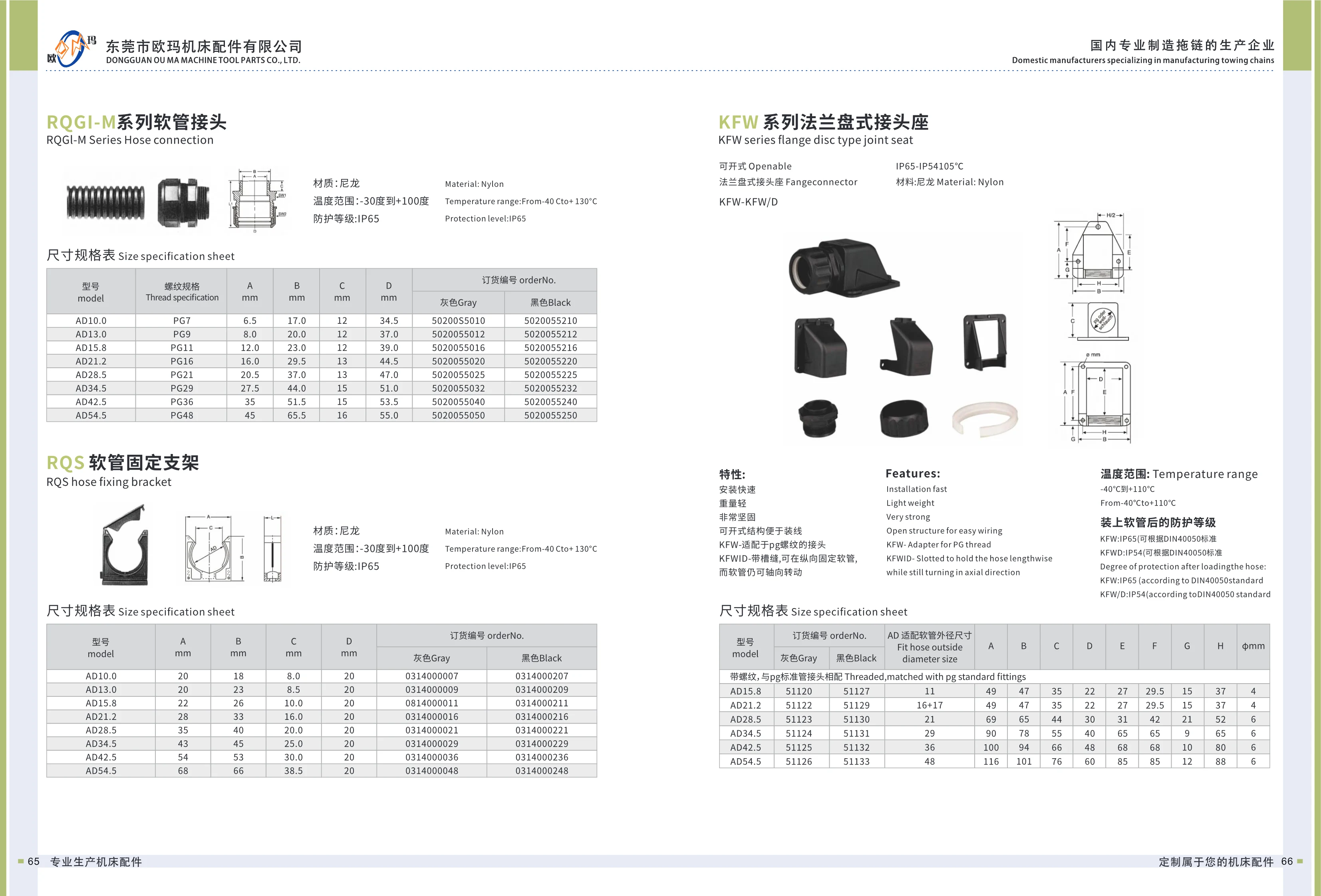
The KFW series flanged connector base is a split nylon conduit fitting used to connect conduit to equipment or junction boxes. Its flanged design incorporates a PG standard threaded fitting. It is quick to install, lightweight and highly robust, while the split design makes cable installation and routing easy. When fitted with conduit, the KFW model has an IP65 protection rating. The KFWID model has a longitudinal slot that secures the conduit lengthwise while allowing it to rotate axially, with an IP54 protection rating. Both ratings are in accordance with DIN 40050. Made of nylon, the fitting operates at temperatures from -40℃~+110℃ and accommodates six conduit outside diameters: AD15.8, AD21.2, AD28.5, AD34.5, AD42.5 and AD54.5. Overall dimensions are defined by A~H and flange diameter φ.
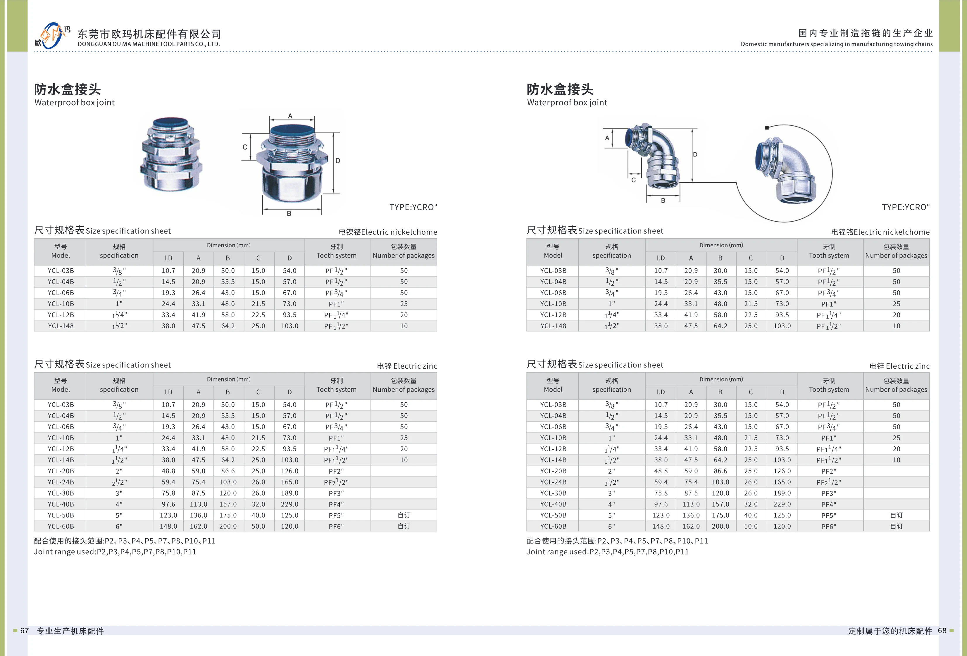
YCL Series Waterproof Box Connectors
YCL series waterproof box connectors are used at cable entry points in electrical enclosures such as machine tools and control cabinets. They provide water and dust protection while securing the cable. The connectors have an electroplated finish (zinc or nickel-chrome) and are available in 12 thread sizes from 3/8 inch to 6 inches. They have PF threads and can be used with P2, P3, P4, P5, P7, P8, P10 and P11 fittings. Key dimensions include thread outside diameter, body diameter and length, which increase with connector size. The series is suitable for industrial automation equipment, machine tool accessories and similar applications, offering corrosion resistance and reliable sealing.
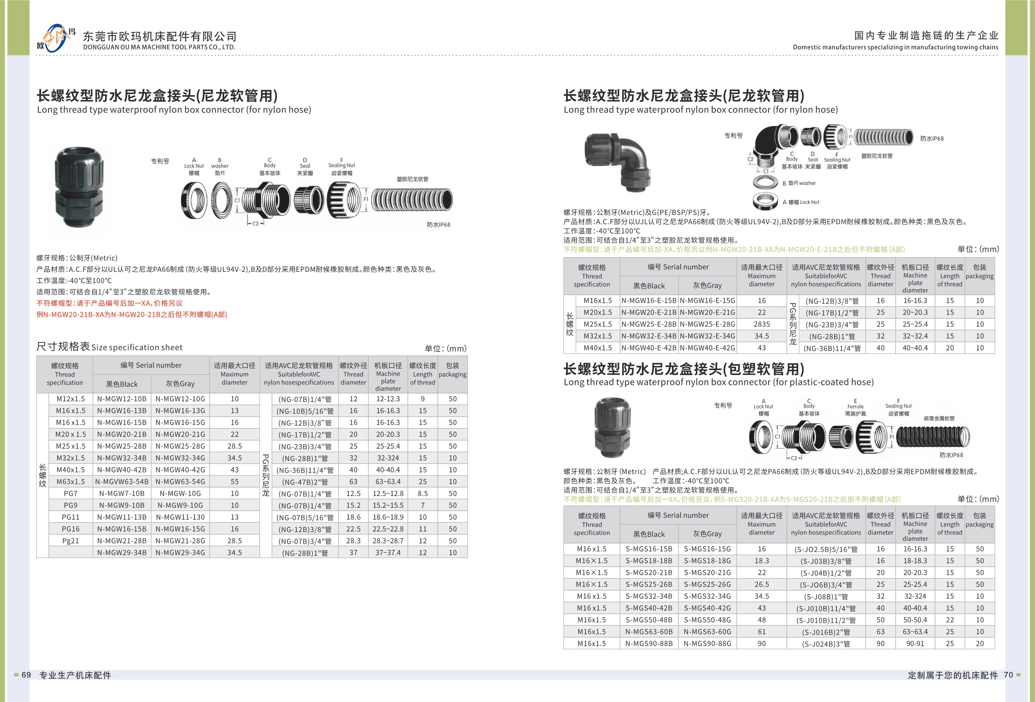
N-MGW Series Long-Thread Waterproof Nylon Box Connector
The N-MGW series long-thread waterproof nylon box connector is designed for use with D series AVC nylon conduit. Made of nylon, it consists of a body, clamping ring and compression nut. Its watertight and dustproof seal protects cable entry points on machine tools, automation equipment, distribution boxes and more. Thread options include metric M threads (M12x1.5~M63x1.5) and PG threads (PG7~PG29), fitting 1/4"~2" nylon conduit. Key dimensions include a maximum applicable diameter of 10~55mm, thread outside diameter of 12~63mm, panel opening diameter of 12~63.4mm and thread length of 8.5~25mm. Packs contain either 50 or 10 pieces. The product is available in red and black; the part number suffix B denotes black and G denotes gray.

OM Series Machine Tool Covers
OM series machine tool covers are available in a range of designs, including bellows way covers, steel covers, lead screw covers, roll-up covers, aluminum curtain covers, and armored covers. They protect guideways, crossbeams, columns, lead screws, shafts, and other components on machine tools and various types of machinery from dust, chips, and coolant. Designed for precise protection to reduce guideway wear, these covers can last 8 years or more in heavy-duty machining applications. Their modular snap-fit design simplifies installation, removal, and maintenance. The fabric meets the UL94 HF-1 flame-retardant rating, and the nano-coating can withstand approximately 50,000 wipes. Covers for horizontal machining centers are mainly available in steel and armored designs: steel covers are commonly used in casting operations, while armored covers suit machining centers with high coolant volumes, long travel, and high speeds. When ordering, provide the maximum extended and minimum compressed dimensions for the X/Y/Z axes, cover travel, crossbeam width, column height, and other relevant parameters.
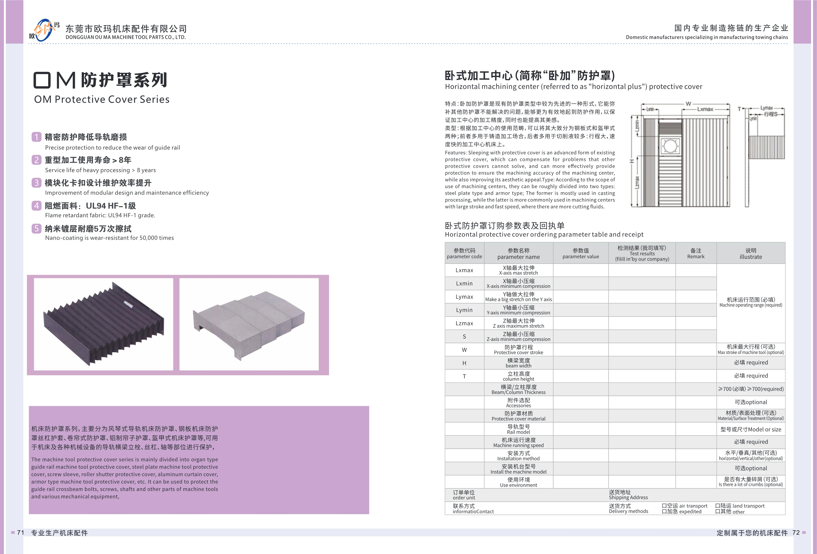
Bellows-Type Machine Tool Guideway Cover
The bellows-type machine tool guideway cover is a folding guideway protection product made from nano-coated flame-retardant fabric with a modular snap-fit structure. It protects guideways, crossbeams, columns, lead screws and shafts on machine tools and other equipment from dust, chips and cutting fluids. The fabric has a UL94 HF-1 flame-retardant rating, and the nano-coating withstands up to 50,000 abrasion cycles. Its service life exceeds 8 years under heavy-duty machining conditions. The modular snap-fit design simplifies installation, removal and maintenance, improving maintenance efficiency. For selection, provide the maximum extended and minimum compressed dimensions for each X/Y/Z axis, cover travel W, crossbeam width H, column height T and other relevant parameters. Covers are customized to the machine tool's actual travel.
Steel Plate Machine Tool Cover and Lead Screw Sleeve
Steel plate machine tool covers and lead screw sleeves belong to the machine tool cover range, alongside bellows guideway covers, roll-up covers, aluminum curtain covers, and armored machine tool covers. They protect moving components such as guideways, crossbeams, columns, lead screws, and shafts on machine tools and other machinery, keeping out chips, cutting fluid, and dust to reduce guideway wear and maintain machining accuracy. The product features a steel plate structure, fabric with a UL94 HF-1 flame-retardant rating, and a nano-coating resistant to up to 50,000 wipes. Its service life exceeds 8 years under heavy-duty machining conditions. A modular snap-fit design simplifies removal, installation, and maintenance, improving maintenance efficiency. Covers for horizontal machining centers are available in steel plate and armored types: steel plate covers are commonly used in cast-iron machining applications, while armored covers are generally used on machines with high cutting-fluid volumes, long travel, and high speeds. When ordering, specify the required dimensions based on the maximum extended and minimum compressed dimensions along the X/Y/Z axes, cover travel W, crossbeam width H, column height T, and other relevant parameters.
Roll-Up Protective Cover
This roll-up protective cover is designed for horizontal machining centers and other machine tools. Its retractable curtain protects guideways, crossbeams, columns, lead screws, shafts and other components from chips, cutting fluid and dust, reducing guideway wear and maintaining machining accuracy. The modular snap-fit design makes maintenance efficient. The fabric is certified to the UL94 HF-1 flame-retardancy rating, and its wear-resistant nano-coating withstands up to 50,000 wipes. Under heavy-duty machining conditions, its service life can exceed 8 years. When ordering, provide the maximum extended and minimum compressed dimensions for the X, Y and Z axes, along with the cover travel W, crossbeam width H, column height T and other relevant parameters. The cover is customized to suit the operating conditions.
Aluminum Curtain Cover
The aluminum curtain cover is a machine tool protective cover made with aluminum alloy slats. It protects guideways, crossbeams, columns, lead screws, shafts and other components on machine tools and industrial equipment from chips, cutting fluid and dust. Its precise protection helps reduce guideway wear, and its service life can exceed 8 years under heavy-duty machining conditions. The modular snap-fit design makes installation and removal easy, significantly improving maintenance efficiency. The fabric is made of UL94 HF-1-rated flame-retardant material, and the surface nano-coating withstands up to 50,000 wipes. These covers are commonly used on machining centers with long travel and high speeds, particularly where large amounts of cutting fluid are present. When ordering, specify the maximum extended and minimum compressed dimensions for the X, Y and Z axes, as well as the cover travel W, crossbeam width H, column height T and other relevant parameters.
Armored Machine Tool Cover
An armored machine tool cover is designed primarily for machines with long travel, high speeds and heavy coolant use, such as horizontal machining centers. It addresses protection challenges that other covers cannot, safeguarding guideways, crossbeams, columns, lead screws, shafts and other components to maintain machining accuracy and improve equipment appearance. Machining center covers are broadly divided into steel plate and armored types. Steel plate covers are commonly used in foundry machining, while armored covers are generally used on machining centers with heavy coolant use, long travel and high speeds. Features include precision protection to reduce guideway wear, a service life of over 8 years in heavy-duty machining, a modular snap-fit design for easier maintenance, flame-retardant fabric rated UL94 HF-1, and a wear-resistant nano-coating that withstands up to 50,000 wiping cycles. When ordering, provide the maximum extended and minimum compressed dimensions for the X/Y/Z axes, cover travel W, crossbeam width H, column height T and other relevant parameters.
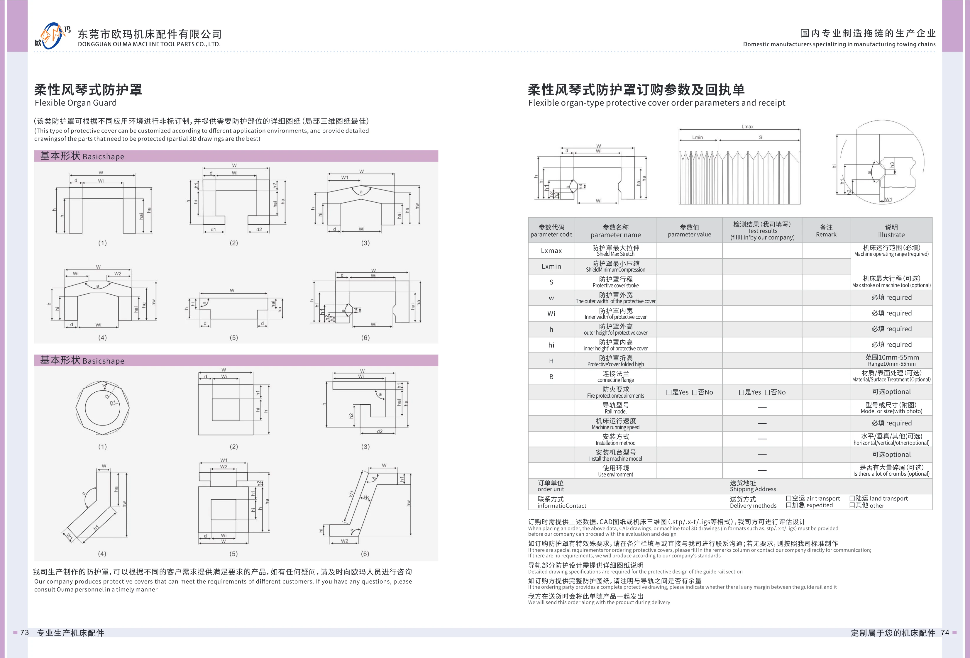
Flexible Bellows Cover
The flexible bellows cover is assembled from PVC support frames (1.5mm thick), fabric, armor plates, and flanges at both ends. It provides extendable protection for moving machine tool components such as guideways, lead screws, and linear scales, keeping out chips, coolant, and dust while providing some vibration damping and seal compensation. This is a custom-made, non-standard product. CAD drawings or 3D models (.stp/.x-t/.igs, etc.) reflecting the machine tool's actual operating range must be provided for design evaluation; unless otherwise specified, the cover is manufactured to factory standards. Key parameters include maximum extended length Lmax, minimum compressed length Lmin, travel S, outer width W and inner width Wi, outer height h and inner height hi, fold height H (range 10~55mm), number of folds n, fabric D, support frame A, and end flanges B. Other specifications include fire resistance requirements, flange material and surface treatment, installation orientation (horizontal/vertical/other), operating speed, and operating environment. The end flanges are made of Q235 by default, and the armor plates of SUS304. When extension and compression space is limited, the armor plate clips must be assembled in an alternating arrangement. The catalog provides two sets of quick-selection parameters in Tables 1 and 2 for determining compressed dimensions from Lmax/Lmin and fold height H, with Lmax ranging from 100~5000mm.
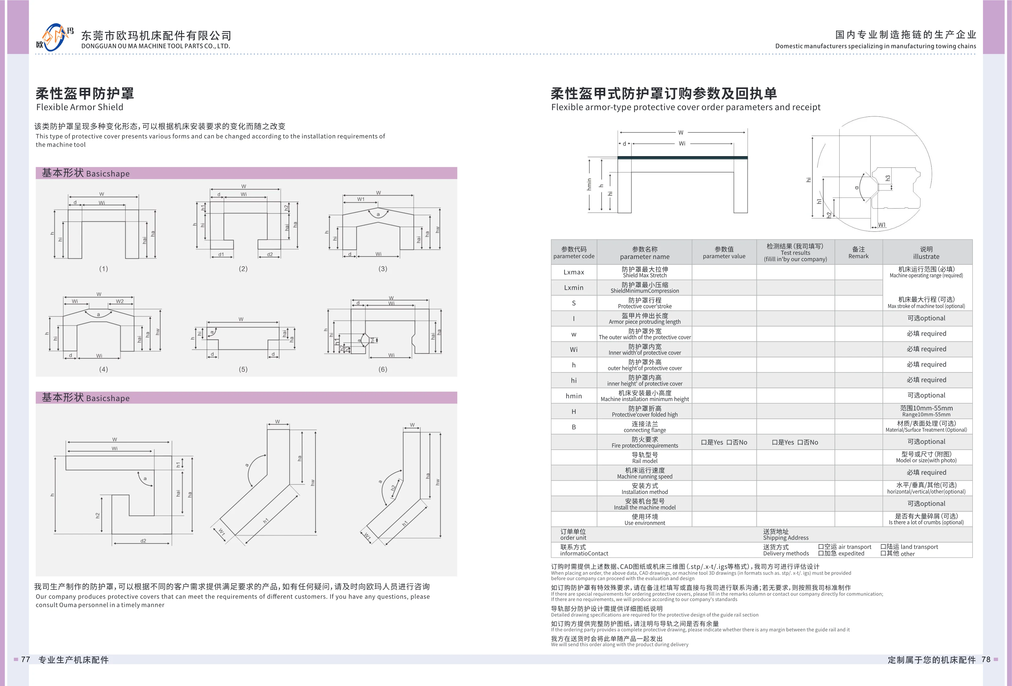
Flexible Armor Shield
The Flexible Armor Shield is a flexible protective cover installed over moving machine tool components such as guideways and lead screws. Made from armor plates joined with flexible material, it can be shaped to suit installation requirements and folds and extends with the moving components. It prevents chips, coolant, dust and other contaminants from entering the guideways and drive system, helping preserve machine accuracy and service life. This product is custom-made to drawings. When ordering, provide the maximum extended length Lxmax, minimum compressed length Lxmin, travel S, armor plate extension length I, outer width w, inner width Wi, outer height h, inner height hi, minimum machine installation height hmin, fold height H (10~55mm), connecting flange material and surface treatment, fire protection requirements, guideway model, machine operating speed, installation orientation (horizontal, vertical or other), machine model and operating environment (including whether large amounts of debris are present). Also provide CAD drawings or 3D files such as .stp, .x-t or .igs. The manufacturer will evaluate the requirements and design the shield before production.
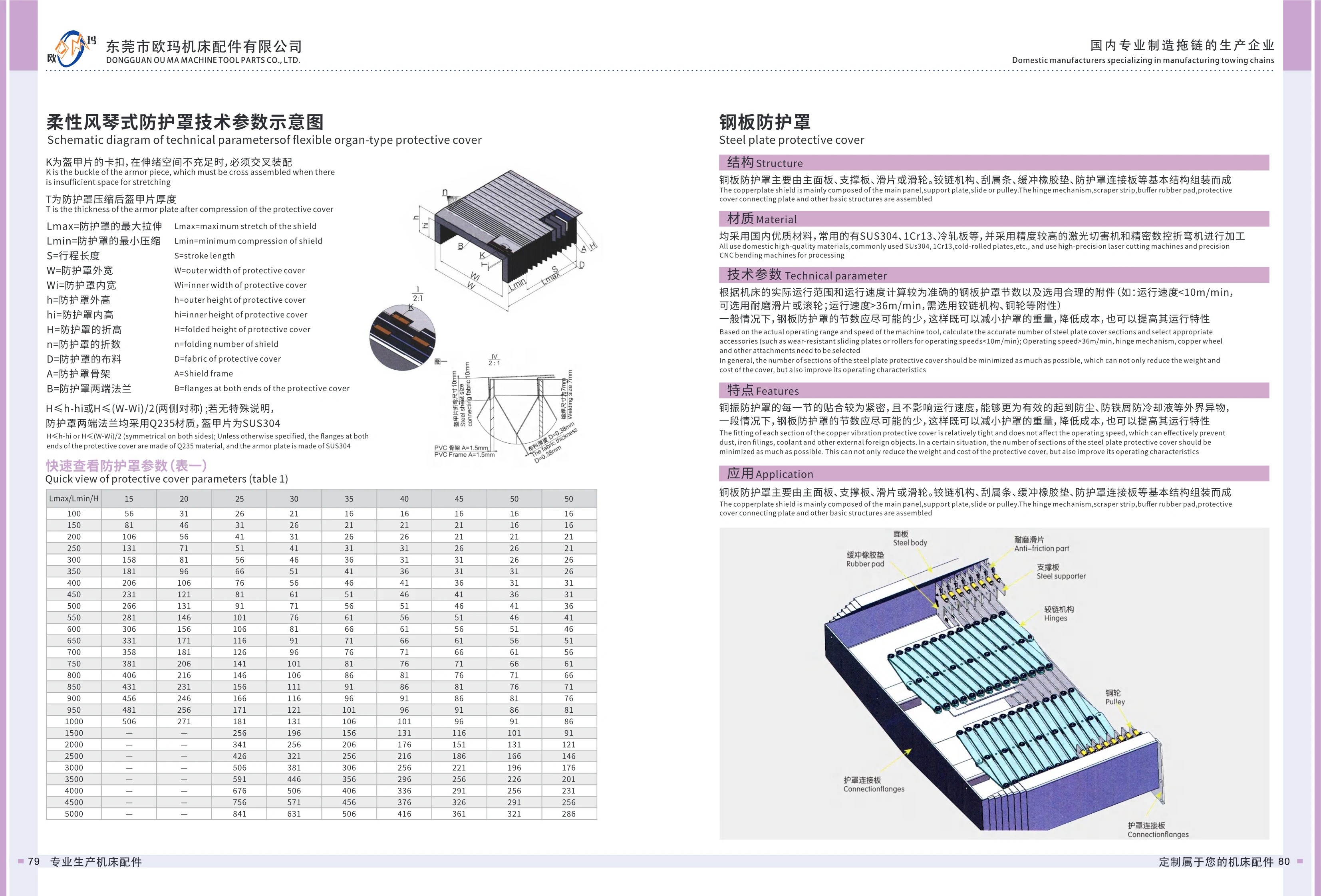
Steel Telescopic Covers
Steel telescopic covers are sheet-metal guards used to protect moving machine tool components such as guideways and lead screws. They typically consist of main panels, support plates, sliding pads or rollers, hinge mechanisms, auxiliary strips, rubber cushioning pads, and cover mounting plates. Common materials include SUS304, 1Cr13, and cold-rolled steel. Manufactured using high-precision laser cutting machines and CNC press brakes, these covers offer a robust structure, smooth operation, resistance to cutting fluids and metal chips, and an attractive appearance. The number of sections and accessories should be selected according to the machine tool's actual travel range and operating speed: wear-resistant sliding pads or rollers can be used at speeds <10m/min, while hinge mechanisms, steel wheels, and other accessories are required at speeds >36m/min. The number of sections should be kept as low as possible while meeting protection requirements to reduce weight and cost and improve operating performance. Products are usually custom-made to drawings; required specifications include length, width, travel, mounting method, guideway model, operating speed, and CAD or 3D drawings.

HXSD-HD Series Cable Carriers
The HXSD-HD series is a heavy-duty cable carrier range designed for short travel, suspended applications, and installations with limited space. It features thinner links and thinner crossbars (HD45 and HD55 series), reducing weight while providing more internal space at an affordable price. Typical applications include toolboxes, warehousing and transport systems, stone-cutting machines, woodworking machines, vehicles, construction machinery, specific long-travel applications, and general mechanical engineering. Testing has demonstrated a service life of more than 10 million cycles. Inner-opening, outer-opening, and S-type designs are available. Example codes include HXSDHE5 and HXSDHE5-48-50C.
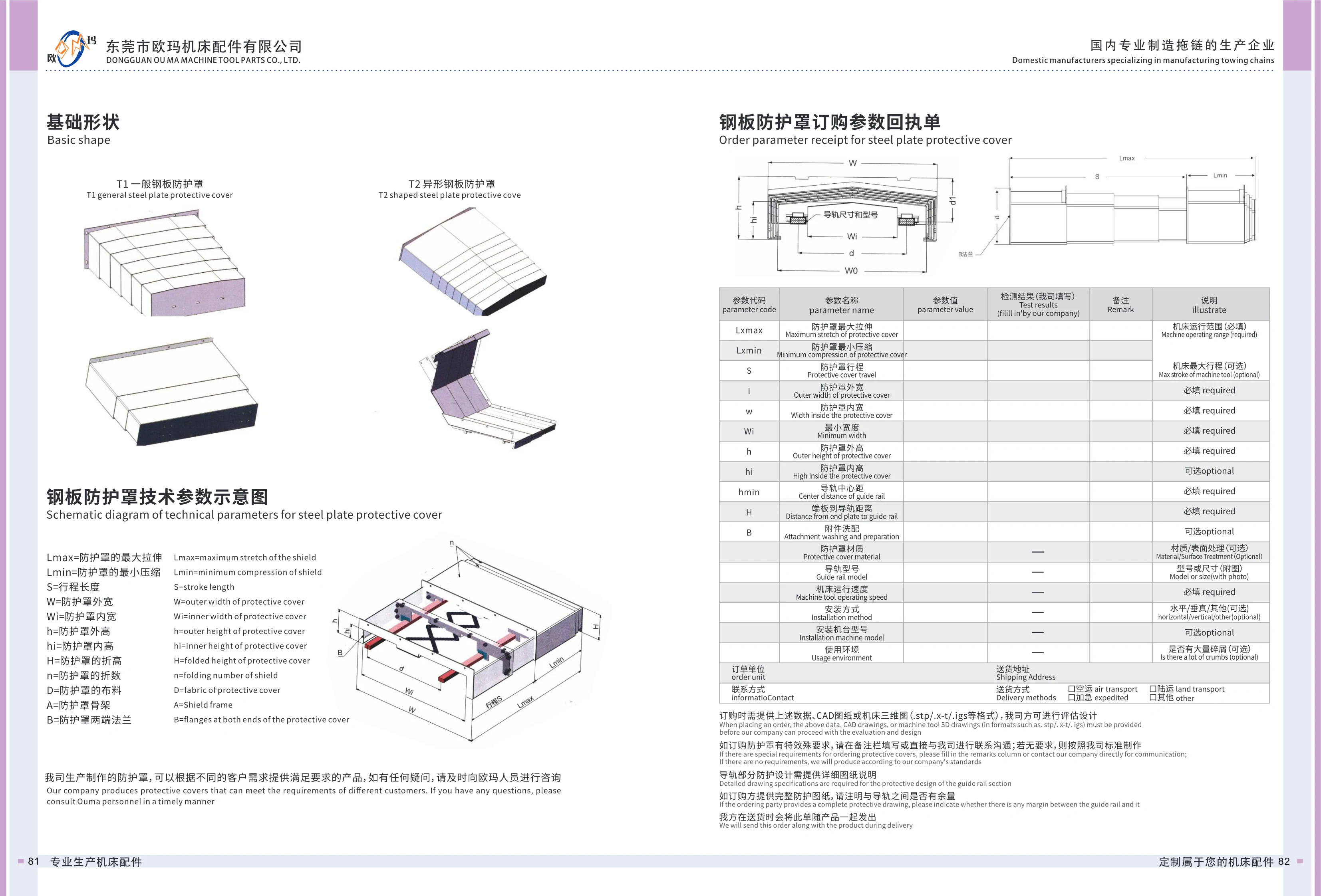
T Series Steel Telescopic Covers
T Series steel telescopic covers protect machine tool guideways and are available in two basic shapes: T1 standard and T2 special-shaped. They can be customized to suit the machine structure, travel and installation space. The covers prevent chips, coolant, dust and debris from entering moving components such as guideways and lead screws, helping maintain precision and extend service life. Key parameters include maximum extended length Lmax, minimum compressed length Lmin, travel S, outer width W, inner width W1, outer height h, inner height h1, fold height H, number of folds n, material D, frame A and flanges B at both ends. When ordering, confirm the guideway center distance, distance from the end plate to the guideway, operating speed, mounting method and operating environment. Material and surface finish options are available. Suitable for machining centers, grinders, gantry machine tools and other equipment.
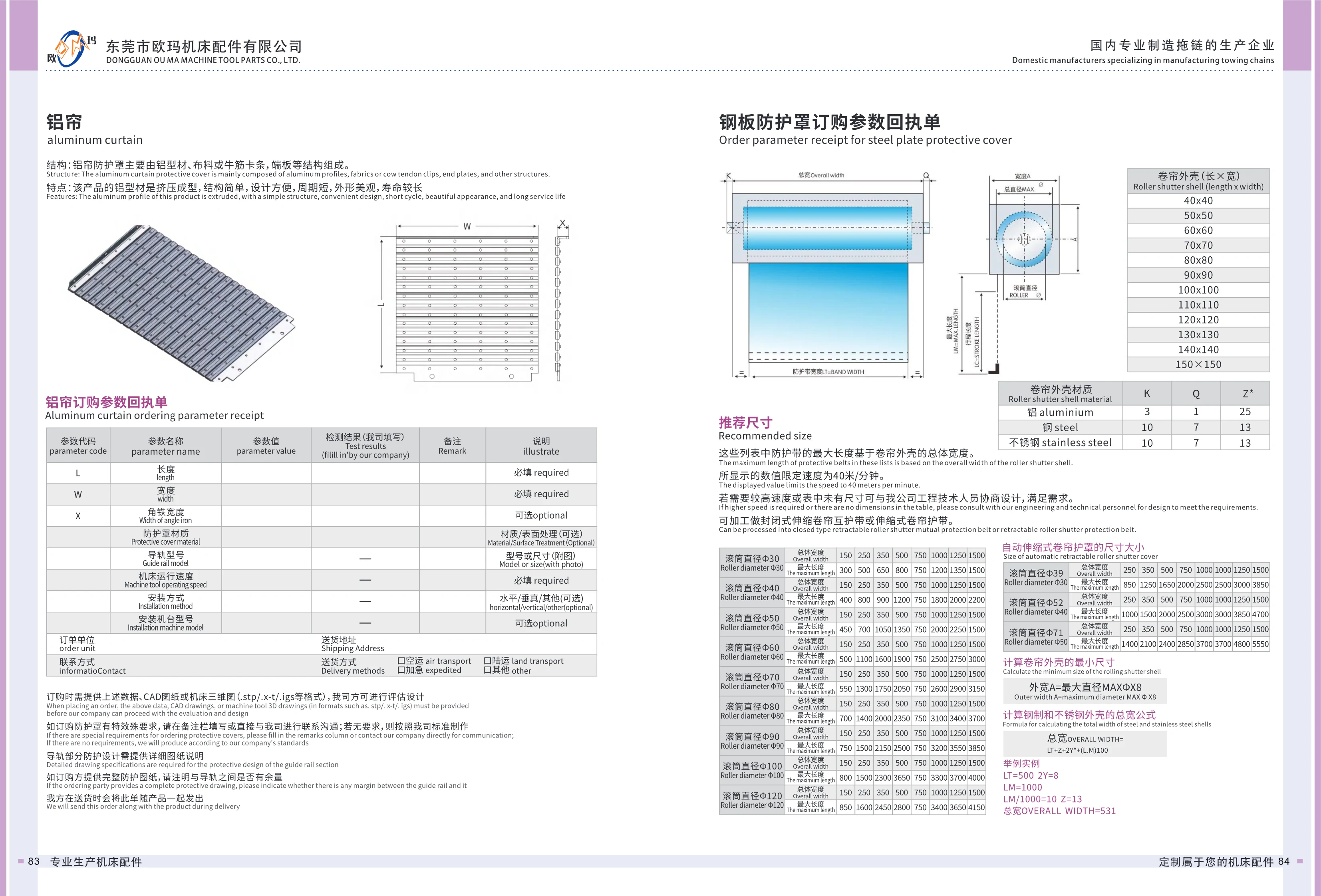
Aluminum Apron Cover
The aluminum apron cover consists primarily of extruded aluminum profiles, fabric or polyurethane retaining strips, and end plates. It protects moving machine tool components such as guideways and lead screws from chips, coolant, and dust. The extruded aluminum construction is simple, easy to design, quick to manufacture, attractive, and durable. It can be customized to suit the machine's travel and available installation space. When ordering, provide parameters including length L, width W, angle iron width, cover material, guideway model, machine operating speed, mounting method, and machine model. Include CAD drawings or a 3D model of the machine in .stp, .x-t, .igs, or similar format for the manufacturer's design assessment. Specify any special requirements in the remarks section; otherwise, the cover will be made to the manufacturer's standards. For guideway protection, provide detailed drawings and indicate whether clearance is required between the cover and the guideway.
Automatic Retractable Roll-Up Cover
The automatic retractable roll-up cover (also known as a retractable roll-up protective belt) is a flexible guard installed over moving machine tool components such as guideways and lead screws. It consists of a housing, roller, protective belt and end plates. A built-in rewind mechanism automatically extends and retracts the belt as the machine component moves, keeping out chips, coolant and dust. Housing materials include aluminum, steel and stainless steel; roller diameters range from Φ30~Φ660. Standard total protective belt lengths are 150、250、350、500、750、1000、1250、1500mm, with corresponding maximum extension lengths of approximately 300~2200mm. The standard recommended operating speed is no more than 40m/min. For higher speeds or dimensions outside those listed in the table, consult our engineers about a custom design. The product can be made as an enclosed retractable roll-up interlocking protective belt or a standard retractable roll-up protective belt. When ordering, provide the length L, width W, angle iron width X, cover material, guideway model, machine operating speed, mounting method and machine model, along with CAD drawings or a .stp/.x-t/.igs 3D model.
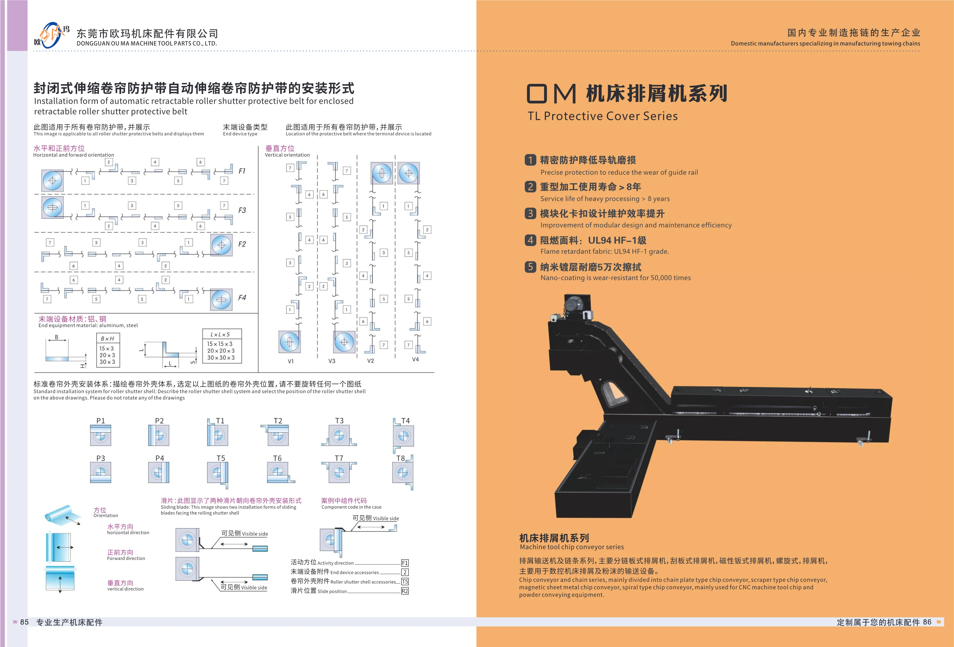
Enclosed Retractable Roll-Up Guard
The enclosed retractable roll-up guard is an automatic machine tool protection device designed to shield linear motion components, such as guideways and lead screws, from chips, coolant and dust. It uses a standard roll-up housing mounting system, with end fittings available in aluminum or steel. Horizontal front-facing and vertical mounting options are available, with adjustable slat orientation and a visible side for easy inspection. Its precision protection reduces guideway wear, its service life exceeds 8 years in heavy-duty machining, and its modular snap-fit design improves maintenance efficiency. The fabric meets the UL94 HF-1 flame-retardant rating, and its nano-coated surface withstands 50,000 wipes. It is suitable for CNC machine tools and automation equipment.
Machine Tool Chip Conveyor Series
The machine tool chip conveyor series transports chips and fines from CNC machine tools. Based on conveyor design, it comprises four types: hinged belt, scraper, magnetic plate and screw conveyors. Hinged belt conveyors use a continuous metal belt to remove large volumes of long, coiled or bundled chips. Scraper conveyors are suited to fine and oily chips. Magnetic plate conveyors use magnetic force to collect fine iron chips and powder, making them suitable for finishing and grinding. Compact screw conveyors are typically used for low-volume chip removal from individual machines. The conveyors can be connected to machine tool coolant tanks, chip collection bins and central chip removal systems to separate chips from cutting fluid and automate removal. A modular snap-fit design simplifies assembly, disassembly and maintenance. Precision guards at critical points reduce guideway wear, and heavy-duty models have a design service life of over 8 years. Optional wear-resistant features, including flame-retardant fabric (UL94 HF-1 grade) and nano-coatings, are available for different machining conditions.
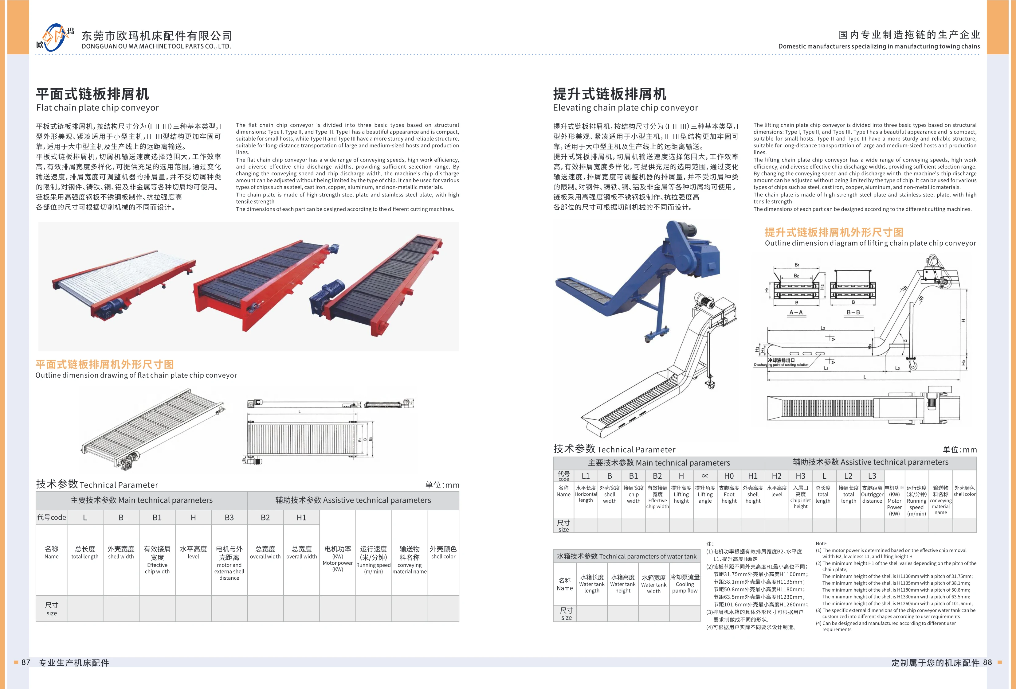
Flat-Plate Chain Chip Conveyor
The flat-plate chain chip conveyor is an auxiliary unit for machine tools and production lines, designed to continuously remove chips from steel, cast iron, copper, aluminum, nonmetals, and other materials. It comes in three basic types, I, II, and III, based on construction and dimensions. Type I has an attractive, compact design suited to small machines; types II and III offer a stronger, more reliable construction for medium and large machines and long-distance conveying on production lines. The conveyor offers a wide range of speeds, high operating efficiency, and a choice of effective chip removal widths. Capacity can be adjusted by changing the conveying speed and chip removal width, regardless of chip type. The chain plates are made from high-strength steel and stainless steel for high tensile strength. Selection is based primarily on overall dimensions: L overall length, B housing width, B1 effective chip removal width, H horizontal height, B2 overall width, B3 distance between motor and housing, and H1 height. Additional parameters include motor power (kW), operating speed (m/min), conveyed material, and housing color. Component dimensions can be designed to suit different chip-producing machines or customized to customer requirements.
Elevating Hinged-Belt Chip Conveyor
The elevating hinged-belt chip conveyor continuously transports and collects chips from machine tools and production lines for centralized discharge. It is available in three basic types based on structural dimensions: Type I has an attractive, compact design suited to small machines, while Types II and III have sturdier, more reliable construction for medium and large machines and long-distance transport on production lines. A wide range of conveying speeds and effective chip removal widths is available. Capacity can be adjusted by changing the speed and width, and the conveyor handles all types of chips, including steel, cast iron, copper, aluminum and nonmetallic materials. The hinged plates are made of high-strength steel or stainless steel and offer high tensile strength. Key dimensions include horizontal length L1, housing width B, chip removal width B1, effective chip removal width B2, lift height H, lift angle H0, housing height H1, overall length L, chip inlet L2 and chip discharge length L3. Motor power is determined by effective chip removal width B2, horizontal length L1 and lift height H. Belt pitches from 31.75~101.6mm are available, with each pitch corresponding to a different minimum housing height. The overall dimensions and structure can be designed and manufactured to customer requirements, making this a custom-built, nonstandard unit.
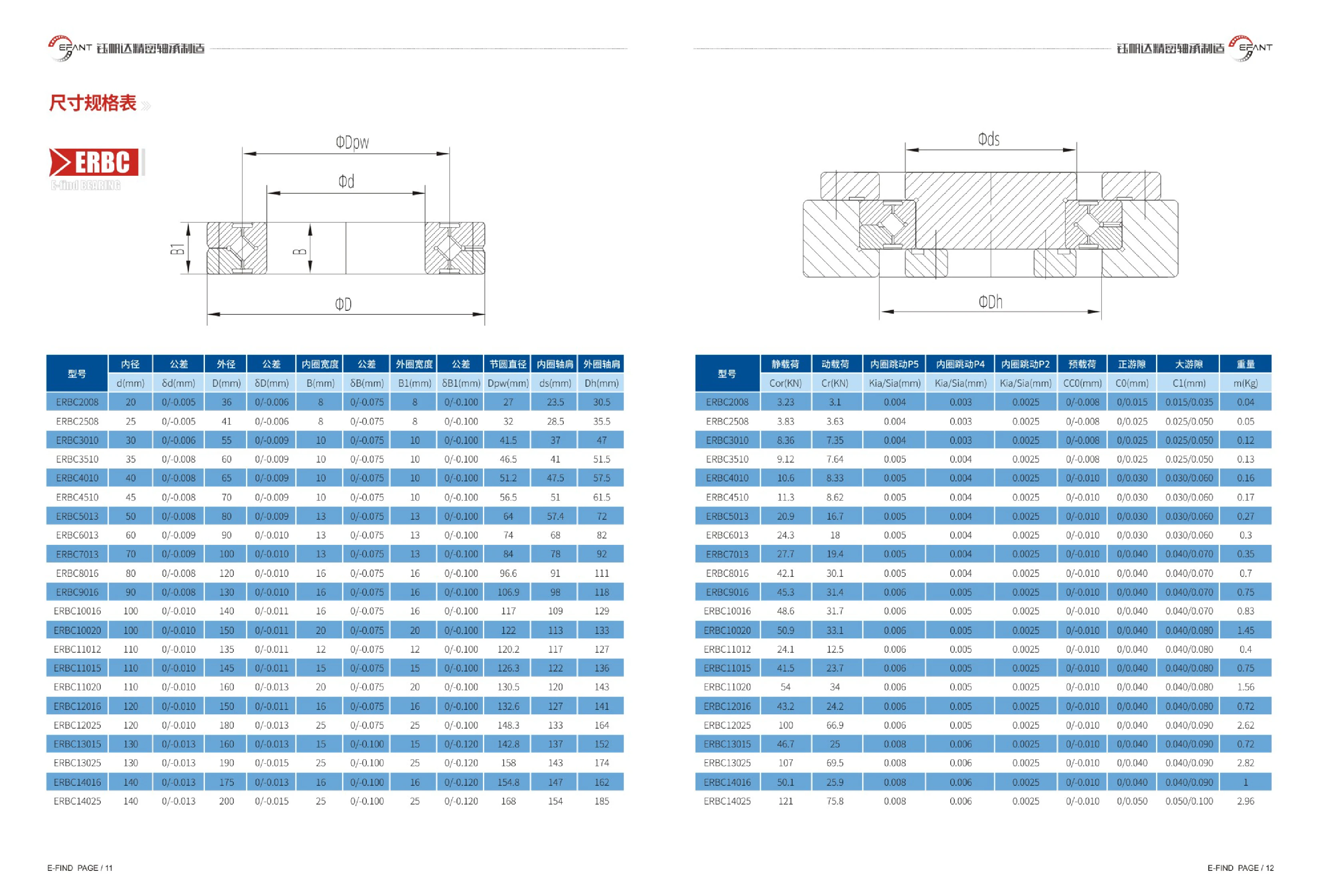
ERBC Series Crossed Roller Bearings
ERBC series crossed roller bearings feature rollers arranged at 90° to one another, allowing them to support radial, axial and moment loads simultaneously. They offer high rigidity, high rotational accuracy and a compact, thin-wall design. The catalog covers bore diameters of 20–1250 mm, outer diameters of 36–1500 mm and widths of 8–110 mm. For each model, it specifies bore diameter, outer diameter, inner ring width and outer ring width tolerances, pitch diameter, and inner and outer ring shoulder dimensions. Three accuracy grades (inner ring runout) are available: P5, P4 and P2, along with three clearance configurations: CC0 (preload), CO (positive clearance) and C1 (large clearance). Static load Cor, dynamic load Cr and weight are also listed. Model numbers consist of the ERBC prefix followed by bore diameter and width figures (for example, ERBC2008 has a 20 mm bore diameter and an 8 mm width). These bearings are commonly used in the rotating sections of CNC rotary tables, swiveling milling heads, direct-drive motors and precision testing equipment. Internal or external gears, additional flanges, surface heat treatment, and matching bearing housings and shafts can be customized.
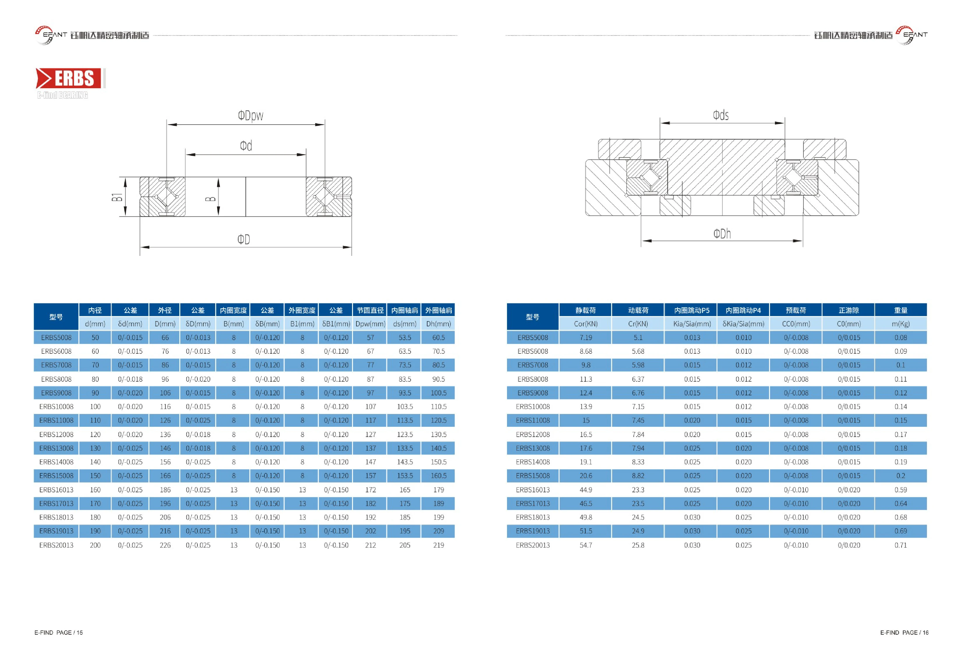
ERBS Series Constant-Section Thin-Wall Bearings
ERBS series constant-section thin-wall bearings are precision ball bearings with a constant radial cross-section and thin walls. They are suited to applications with limited space that require low weight and high rigidity, such as robot joints, aerospace, medical devices, semiconductor equipment and precision rotary mechanisms. The series has bore diameters of 50~200 mm, outside diameters of 66~226 mm and two width options of 8 mm and 13 mm. Pitch diameters range from 57~212 mm, inner ring shoulder diameters from 53.5~205 mm and outer ring shoulder diameters from 60.5~219 mm. Static load ratings are 7.19~54.7 kN and dynamic load ratings are 5.1~25.8 kN. Options include P5/P4 inner ring runout grades, CC0 preload and CO positive clearance. Each bearing weighs 0.08~0.71 kg.
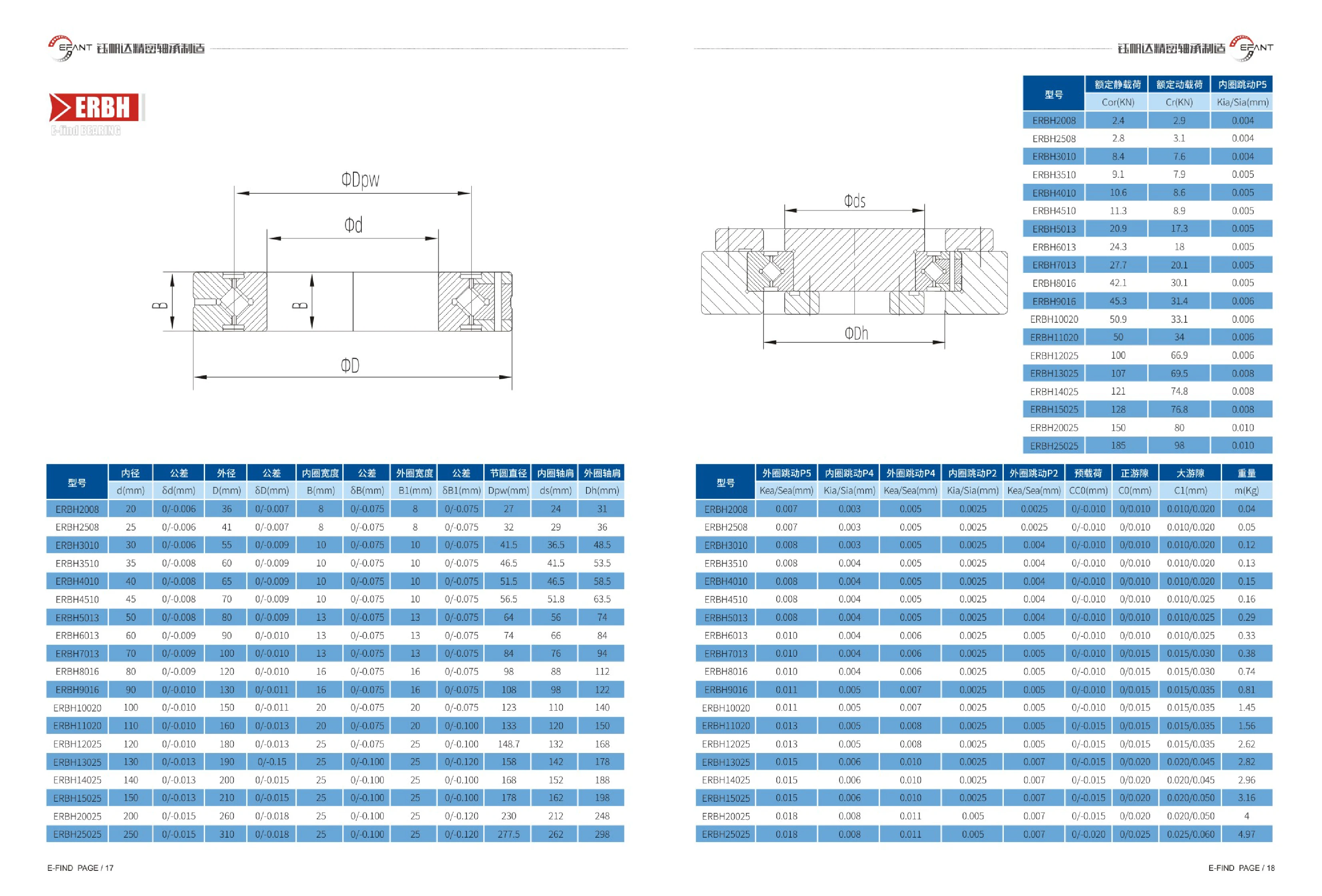
ERBH Series Constant-Section Thin-Wall Bearings
The ERBH series consists of precision constant-section (thin-wall) bearings with inner and outer rings of equal width. The range includes 19 sizes, with inner diameters of 20~250mm, outer diameters of 36~310mm, and widths of 8~25mm. The catalog specifies inner diameter d, outer diameter D, inner ring width B, outer ring width B1, pitch diameter Dpw, inner ring shoulder ds, outer ring shoulder Dh, and their respective tolerances. It also lists P5, P4, and P2 inner/outer ring runout values, preload groups (such as 0/-0.010 and 0/-0.020), positive clearance groups (0/0.010 and 0/0.025), large clearance groups (0.010/0.020, 0.010/0.025, 0.020/0.050, and 0.025/0.060), and reference weights for each size. These bearings are suitable for industrial robot joints and reducers, precision rotary tables, semiconductor and medical equipment, optical instruments, and other applications with limited cross-sectional space that require high rigidity and low runout. Select a model by its inner diameter and width, then choose the P5/P4/P2 accuracy class and preload or clearance group according to the equipment's precision and rigidity requirements.
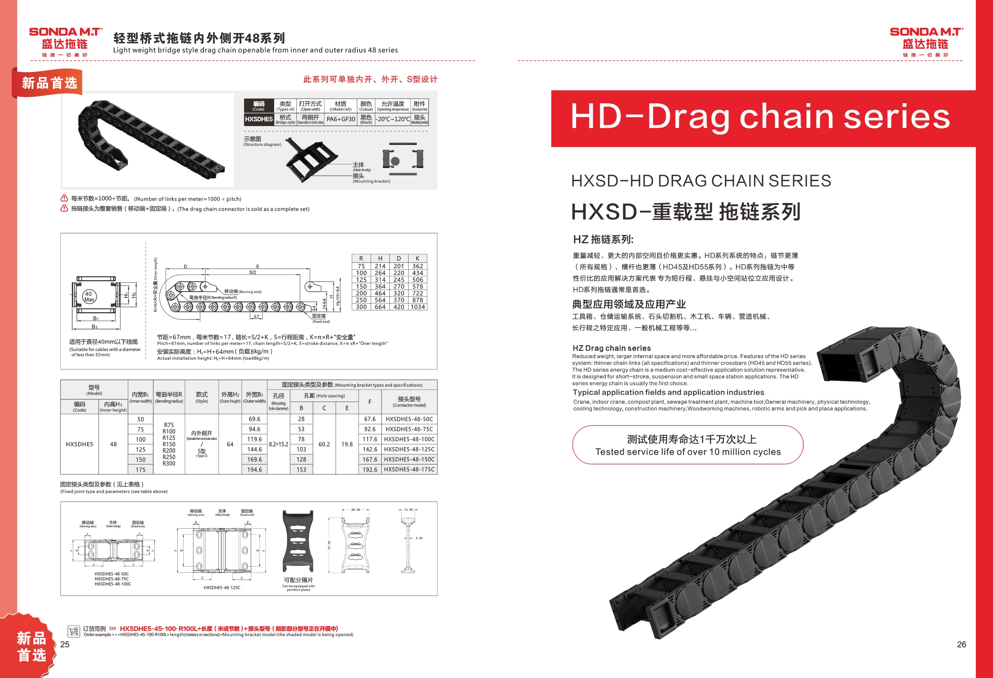
HXSD-HD Heavy-Duty Cable Carrier Series
The HXSD-HD Heavy-Duty Cable Carrier Series, also known as the HZ Cable Carrier Series, is designed for short travel distances, suspended applications, and confined spaces. The series features thinner links and thinner crossbars (HD45 and HD55 series), reducing weight while providing more interior space at an affordable price. Typical applications include toolboxes, warehousing and conveying systems, stone-cutting machines, woodworking machines, vehicles, construction machinery, specific long-travel applications, and general mechanical engineering. Testing has demonstrated a service life of over 10 million cycles. The series is available in various models, including the HXSDHE5 base model, with length suffixes such as -48-50C.
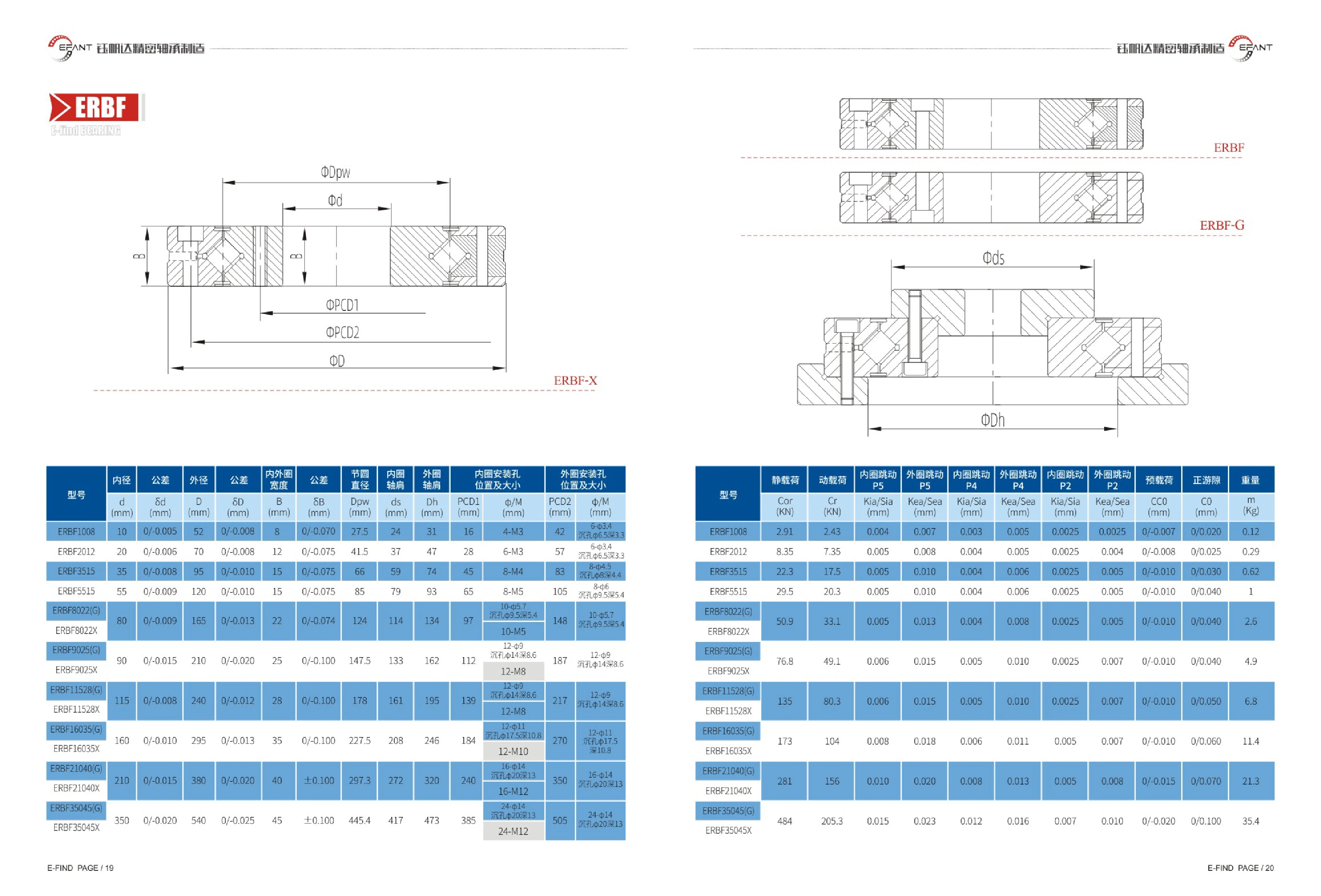
ERBF-X Series Crossed Roller Bearings
The ERBF-X series comprises crossed roller bearings with mounting holes in both the inner and outer rings. Their rollers are arranged at 90° to one another, allowing them to support radial, axial and moment loads simultaneously. They offer high rigidity, high rotational accuracy and a compact design. Applications include robot joints, precision rotary tables, indexing tables, medical equipment and rotary mechanisms in industrial automation. Models cover inner diameters of 10~350 mm and outer diameters of 52~540 mm, with P5/P4/P2 runout grades and preload or positive clearance options. The main difference between G and X types is the outer ring mounting hole design: the X type uses threaded holes.
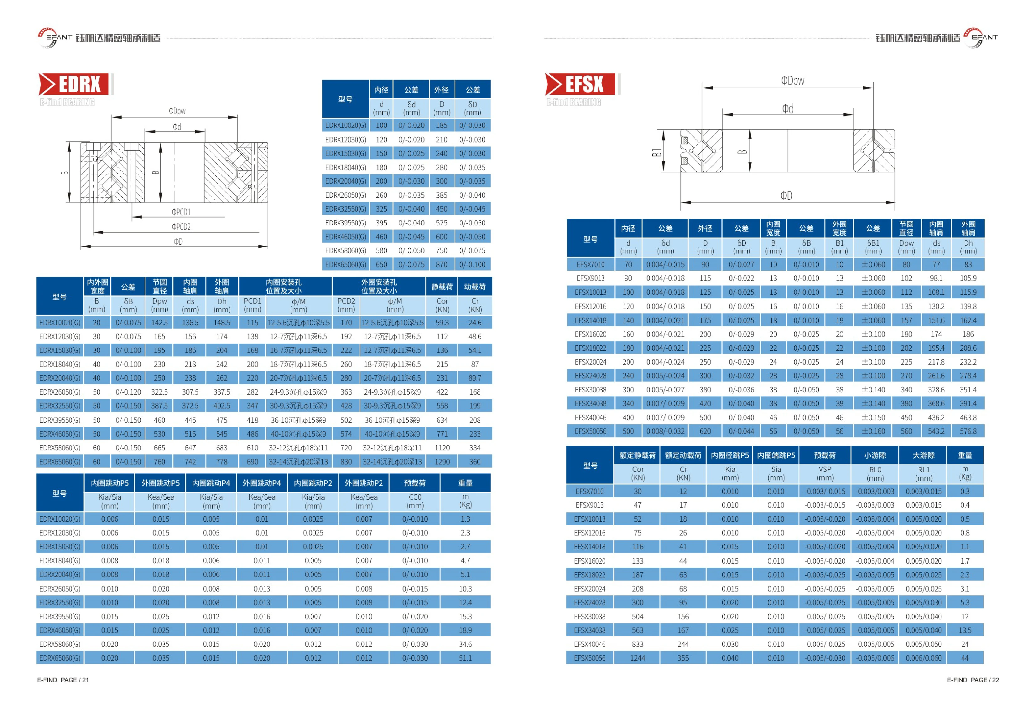
EDRX/EFSX Series Thin-Section Bearings
EDRX/EFSX series thin-section bearings are suitable for precision rotating assemblies with limited installation space, such as robot joints, precision rotary tables, and indexing tables. The EDRX type is available in 15 sizes, with bore diameters of 100~900 mm and outer diameters of 185~1100 mm. Bore tolerances range from 0/-0.020~0/-0.100 mm and outer diameter tolerances from 0/-0.030~0/-0.100 mm. The EFSX type is available in 13 sizes, with bore diameters of 70~500 mm and outer diameters of 90~620 mm. Inner and outer ring widths, pitch circle diameter, and inner and outer ring mounting-hole pitch circle diameters are also specified. Bore tolerance is tightened to 0.004~0.008 mm, width tolerance is 0/-0.010~0/-0.050 mm, and mounting-hole pitch tolerance is ±0.06~±0.16 mm, facilitating direct bolting to adjacent structures. Select the size by matching the bore diameter, outer diameter, and tolerance class to the equipment shaft system's accuracy requirements.
EFSX Series Crossed Roller Bearings
The EFSX series consists of thin-section crossed roller bearings with the same dimensions as the SX0118 series. Rollers are arranged at 90° to one another, allowing the bearings to accommodate radial loads, axial loads in both directions, and overturning moments simultaneously, with high rigidity and rotational accuracy. Model numbers consist of EFSX + bore diameter + width; for example, EFSX7010 denotes a bore diameter of 70mm and a width of 10mm. The catalog covers 13 sizes with bore diameters of 70~500mm, outside diameters of 90~620mm, and widths of 10~56mm. Bore diameters have unilateral negative tolerances starting at 0.004~0.008mm; outside diameter tolerance is 0~-0.044mm, inner ring width tolerance is 0/-0.010~0/-0.050mm, and outer ring width tolerance is ±0.060~±0.160mm. The catalog also specifies the pitch circle diameter and the mounting hole pitch circle dimensions (center distances) for the inner and outer rings, facilitating direct bolt mounting. These bearings are widely used in applications requiring high rigidity and rotational accuracy, including robot joints, precision rotary tables, indexing tables, radar, and medical equipment.