product — Page 73
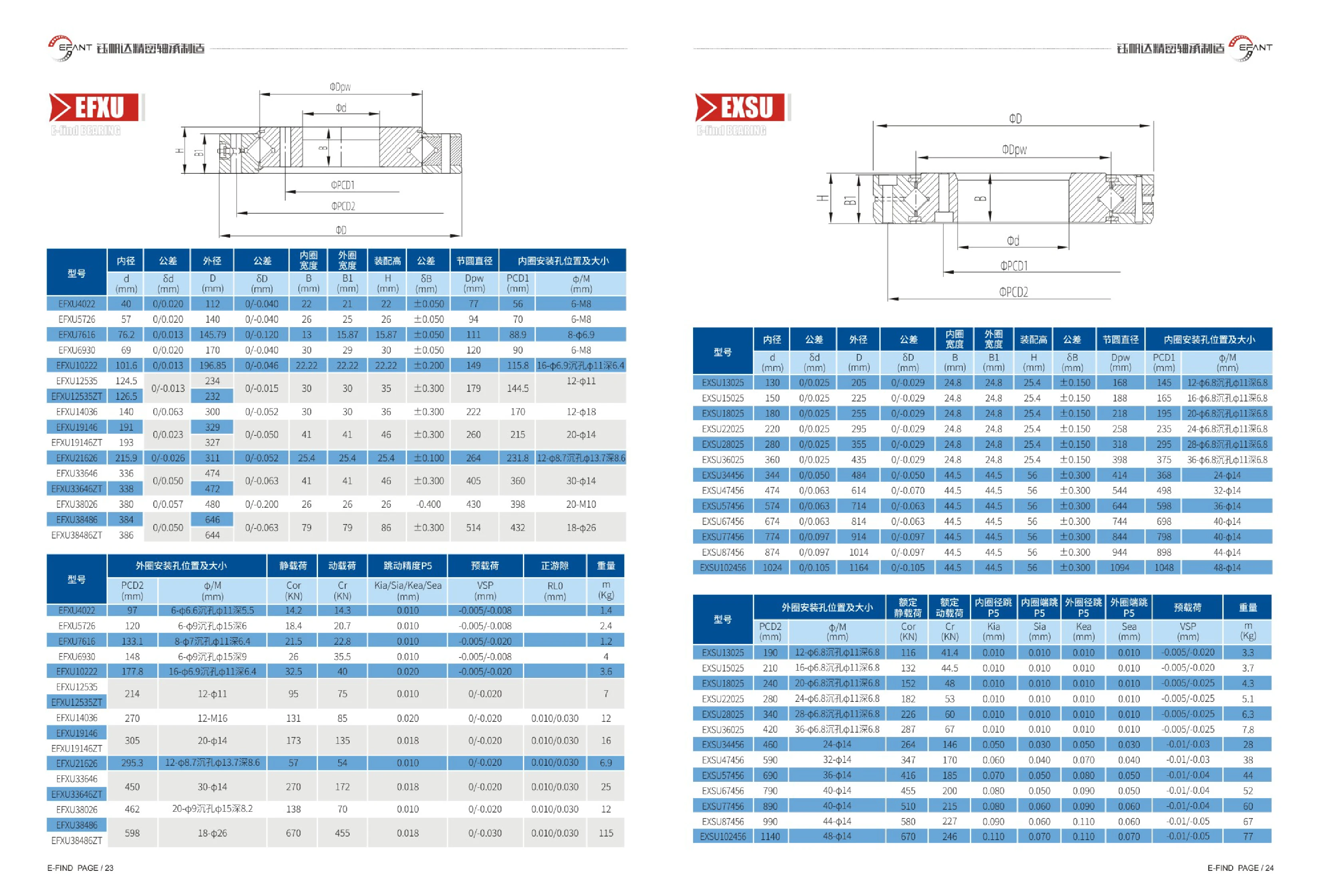
EFXU Series Bearings
The EFXU series consists of slewing bearings (turntable bearings) with mounting holes in the inner ring. The catalog provides a complete range of dimensions and tolerances in tabular form. The series covers inner diameters of 40~384 mm (including the imperial conversions of 76.2, 101.6, and 215.9 mm for EFXU7616, EFXU10222, and EFXU21626, respectively), outer diameters of 112~646 mm, inner ring widths of 13~79 mm, outer ring widths of 15.87~79 mm, and assembly heights of 15.87~86 mm. Each size specifies the inner diameter tolerance (e.g., 0/0.020), outer diameter tolerance (e.g., 0/-0.040), assembly height tolerance (±0.050~±0.300), pitch circle diameter Dpw, inner ring mounting hole pitch circle PCD1, and the type and number of inner ring mounting holes (M8 and M10 threaded holes, φ6.9, φ8.7, φ11, φ14, φ18, and φ26 through holes, and counterbored versions). The ZT model suffix denotes a variant with inner and outer diameters different from the standard model. These bearings are suitable for load-bearing and drive structures in low-speed rotation, oscillation, or positioning applications.
EXSU Series Bearings
EXSU series bearings are listed in the catalog under both EXSU and EFXU designations, covering bore diameters from 40mm to 1024mm. Key dimensions include bore diameter d, outside diameter D and its upper and lower deviations, inner ring width B, outer ring width B1, assembly height H and its tolerance, pitch circle diameter Dpw, and inner ring mounting hole pitch circle PCD1 and hole type (such as 6-M8, 12-φ11, and 20-φ14; some have φ6.9 holes with φ11 counterbores 6.4 deep). Tolerances vary by size: smaller sizes typically have bore tolerances of 0/0.020 and outside diameter tolerances of 0/-0.040; medium and large sizes use wider tolerances of 0/0.063 and 0/-0.063, respectively, while assembly height tolerances increase from ±0.050 to ±0.150 or ±0.300. Models with the ZT suffix have dimensions similar to standard models and are distinguished by their structure or variant. This series is widely used in rotary tables, indexing tables, articulated mechanisms, and other applications requiring high rigidity and rotational accuracy.
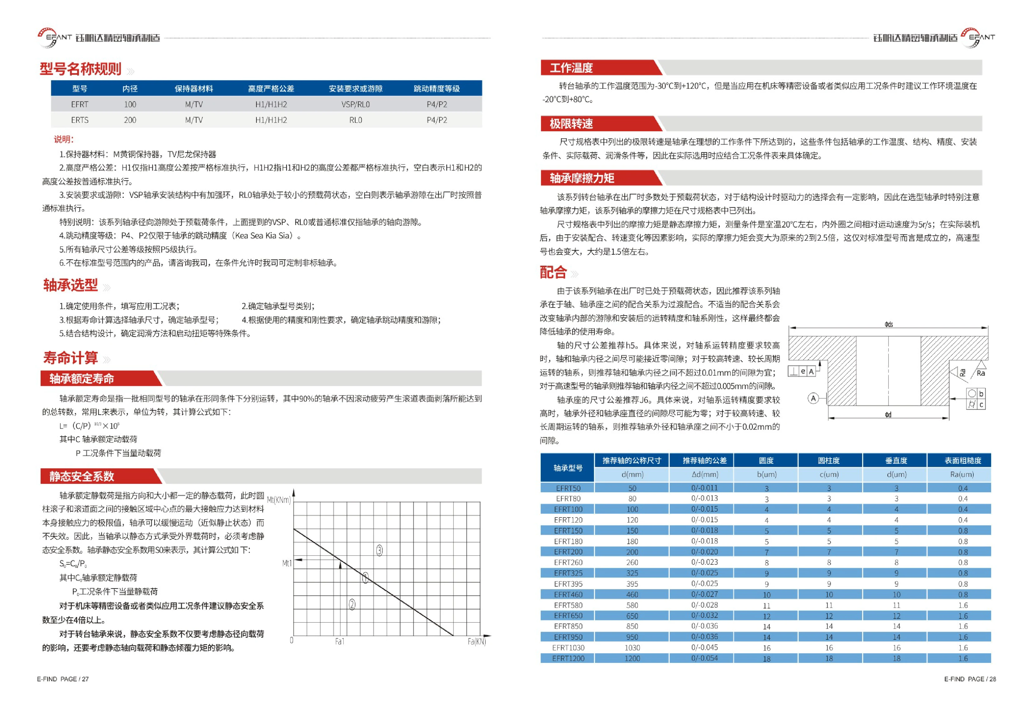
EFRT Series Rotary Table Bearings
The EFRT series comprises precision rotary table bearings, including the ERTS variant, for applications such as machine tool rotary tables, indexing tables and CNC rotary tables that must simultaneously support axial loads, radial loads and tilting moments. Most bearings are supplied preloaded and use a combined axial and radial cylindrical roller arrangement. A reinforcing ring (VSP) can be added to increase shaft system rigidity. The model designation combines bore diameter, cage material (M for brass cage / TV for nylon cage), tight height tolerance (H1 or H1H2), mounting requirements or clearance (VSP for a reinforcing ring, RL0 for reduced preload, blank for the normal standard), and runout accuracy class (P4 / P2). Dimensional tolerances are uniformly specified to P5. Bore sizes range from 50~1200 mm, with an operating temperature of -30℃~+120℃ (-20℃~+80℃ recommended for precision equipment). An H5 shaft tolerance and J6 housing tolerance are recommended, using a transition fit.
EFRT/ERTS Series Turntable Bearings
EFRT/ERTS series turntable bearings are high-rigidity precision turntable bearings (slewing bearings) with mounting holes in the inner and outer rings. They are used in machine tool rotary tables, indexing tables, vertical-to-horizontal conversion heads, and other applications requiring simultaneous support of axial loads, radial loads, and tilting moments. The bearings are generally supplied preloaded. Transition fits are recommended for the shaft and bearing housing (shaft tolerance h5 and housing tolerance J6). Radial clearance is under preload; VSP, RL0, and the standard version refer only to axial clearance. Brass cages (M) or nylon cages (TV) are available. Height tolerances are available in the tighter H1 or H1H2 grades. Mounting configurations include VSP with a reinforcing ring, RL0 with reduced preload, and the standard version. Runout accuracy is available in P4/P2; dimensional tolerances for all bearings conform to P5. Bore diameters range from 50~1200mm, and the operating temperature is -30℃~+120℃. Actual friction torque is approximately 2~2.5 times the static value in the table (approximately 1.5 times for the high-speed type).
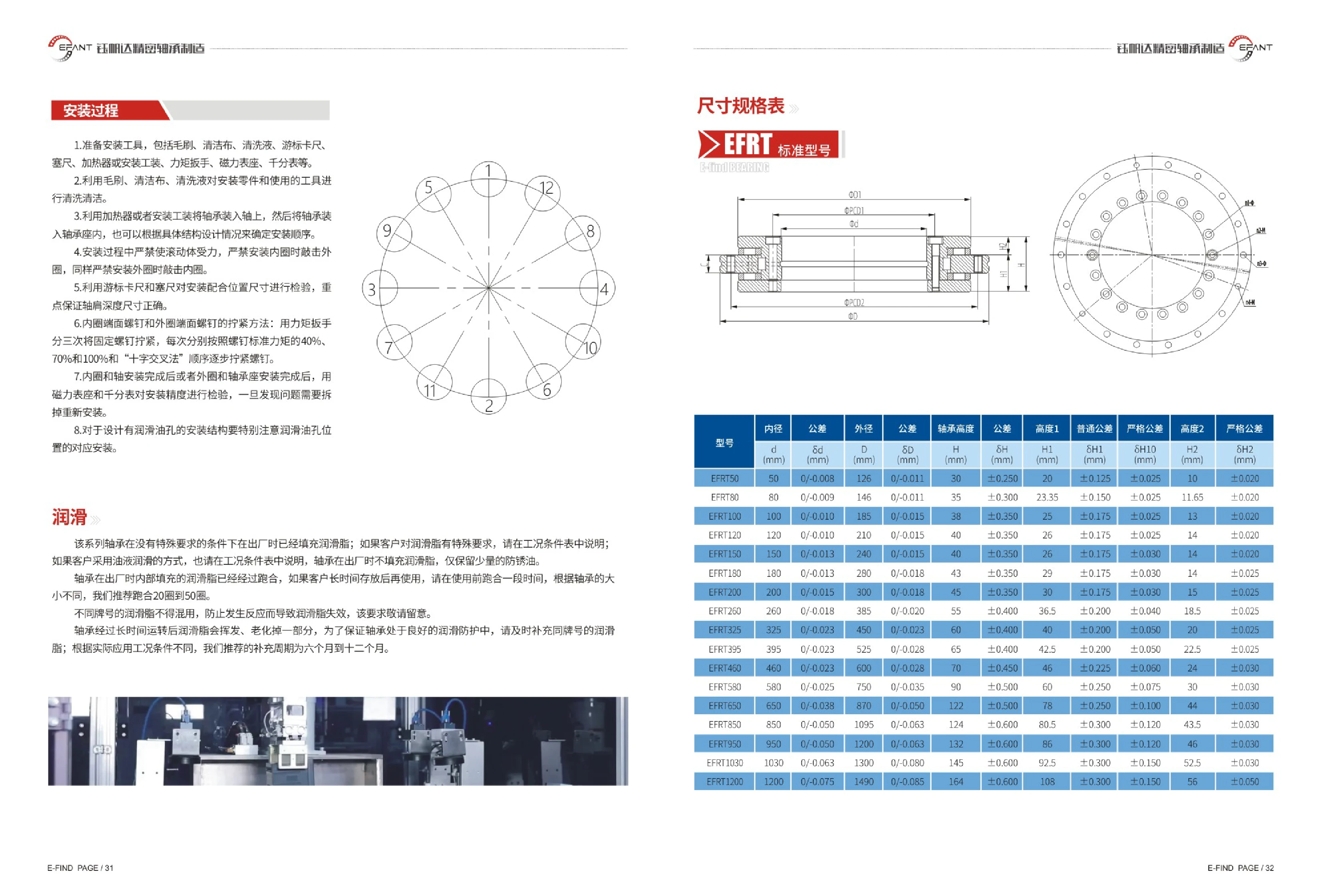
EFRT Series Bearings
EFRT series bearings are medium- to large-sized bearings with mounting screw holes in the end faces of the inner and outer rings. The 17 sizes cover bore diameters of 50~1200mm, outside diameters of 126~1490mm and bearing heights of 30~164mm. The catalog specifies five dimensions: bore diameter, outside diameter, bearing height, height 1 and height 2. It lists unilateral negative tolerances for bore and outside diameters (e.g., 0/-0.008 for a 50mm bore and 0/-0.075 for a 1200mm bore), symmetric height tolerances (±0.250~±0.600), and normal and strict tolerance options for heights 1 and 2, allowing selection according to equipment accuracy requirements. Before installation, clean the parts and tools, then fit the bearing using a heater or dedicated mounting tool. Never apply force through the rolling elements or strike the non-fitted ring. Use a torque wrench to tighten the inner and outer ring end-face screws in a crosswise sequence, in three stages at 40%, 70% and 100% of the standard torque. Check installation accuracy with a dial indicator on a magnetic base, paying particular attention to the shoulder depth dimension. Bearings are supplied prefilled with grease according to the fit requirements. Oil lubrication can be used instead to suit the customer's operating conditions, in which case only rust-preventive oil is retained; different grades of
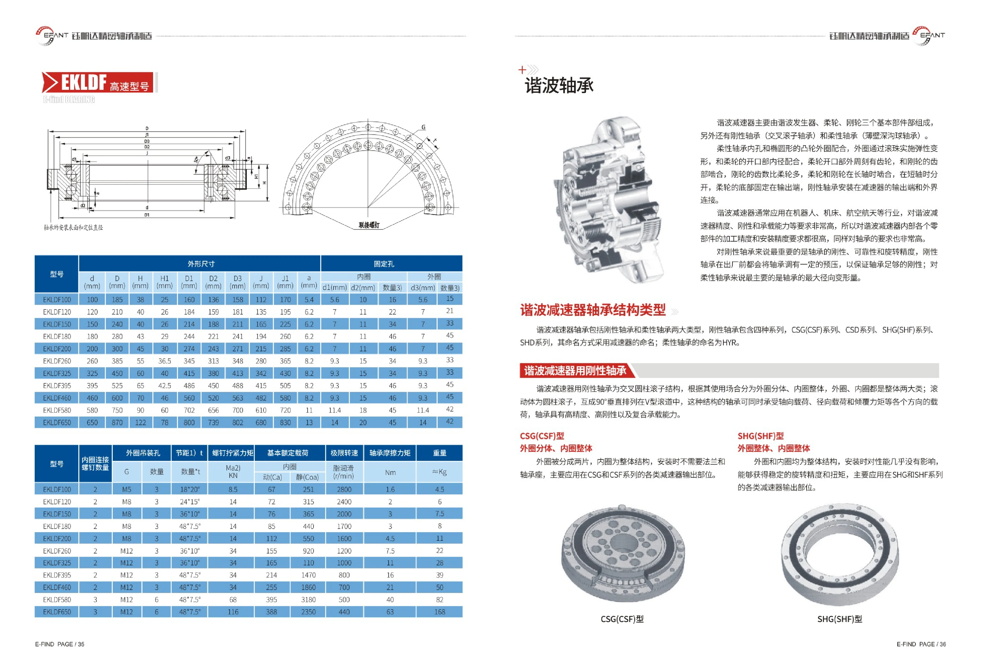
EKLDF Series Rigid Bearings for Harmonic Drive Reducers
EKLDF series rigid bearings for harmonic drive reducers feature crossed cylindrical rollers arranged perpendicular to each other at 90° in a V-shaped raceway. They can simultaneously accommodate axial loads, radial loads, and overturning moments. Depending on the application, they are available in two configurations: a split outer ring with an integral inner ring, or integral outer and inner rings. They offer high precision, high rigidity, and combined load capacity. The range covers d=100~650 mm in 11 sizes and is suitable for harmonic drive reducers, robot joints, and precision rotary mechanisms.

CSG(CSF) Series Rigid Bearings for Harmonic Reducers
CSG/CSF series rigid bearings for harmonic reducers feature a crossed cylindrical roller design, with rollers arranged perpendicular to each other at 90° in a V-shaped raceway. They simultaneously accommodate axial loads, radial loads, and overturning moments, providing high precision, high rigidity, and combined load capacity. Depending on the application, they are available in two main configurations: a split outer ring with an integral inner ring, or integral outer and inner rings. Rigid bearing series include CSG(CSF), CSD, and SHG(SHF). This page lists 11 sizes with bore diameters d=100~650mm, along with overall and mounting dimensions including d, H, H1, D1, D2, D3, J, J1, and a, as well as mounting hole specifications for the inner and outer rings. These bearings are suitable for harmonic reducer output support and precision rotary applications.
CSD Series Rigid Bearings for Harmonic Drives
Rigid bearings for harmonic drives feature crossed cylindrical rollers arranged at 90° to one another in a V-shaped raceway. They simultaneously accommodate axial loads, radial loads, and overturning moments, offering high precision, high rigidity, and strong combined-load capacity. Depending on the application, they are available in two main designs: a split outer ring with an integral inner ring, or integral inner and outer rings. Rigid bearing series include CSG(CSF), CSD, and SHG(SHF), and are commonly used in precision drive applications such as harmonic drives, robot joints, and precision rotary tables. This page lists EKLDF specifications with bore diameters d=100~650 mm, outer diameters of 185~870 mm, and heights of 38~122 mm. Mounting hole and raceway dimensions are also provided to support selection and installation design.

SHG(SHF) Series Rigid Bearings for Harmonic Reducers
Rigid bearings for harmonic reducers use a crossed cylindrical roller design, with cylindrical rollers arranged at 90° to one another in V-shaped raceways. They can simultaneously support axial loads, radial loads, and tilting moments, providing high precision, high rigidity, and combined load capacity. Depending on the application, they are divided into two main types: split outer ring with integral inner ring, and integral inner and outer rings. The rigid bearing range comprises four series: CSG(CSF), CSD, SHG(SHF), and SHG(CSF). The catalog lists 11 sizes from EKLDF100 to EKLDF650, with bore diameter d ranging from 100mm to 650mm. Overall height, mounting hole dimensions, and other dimensions increase with bore diameter. These bearings are widely used in precision transmission applications such as industrial robot joints and harmonic reducers.

CSD Flexible Bearings for Harmonic Drive Reducers
Flexible bearings for harmonic drive reducers are available in CSD, SHD and other configurations. The CSD type has one-piece inner and outer rings and the same outside diameter as the CSG type, but offers greater rigidity. It is used at the output of CSD series reducers. The SHD type has a one-piece toothed inner ring that meshes directly with the flexspline teeth. It is lower in height than the SHG and is used at the output of SHD series reducers. These thin-walled bearings deform elastically when fitted to a cam and are subjected to alternating stress. The inner and outer rings and rolling elements are made of high-carbon chromium bearing steel, and the cage is a one-piece nylon design. The catalog lists the dimensions of CSG(CSF)-14~-65 bearings (d, D, H, C, B, H2, D1, D2, d1, d2). The operating temperature range is -20℃~+80℃. The bearings are filled with lithium complex grease and preloaded before shipment.
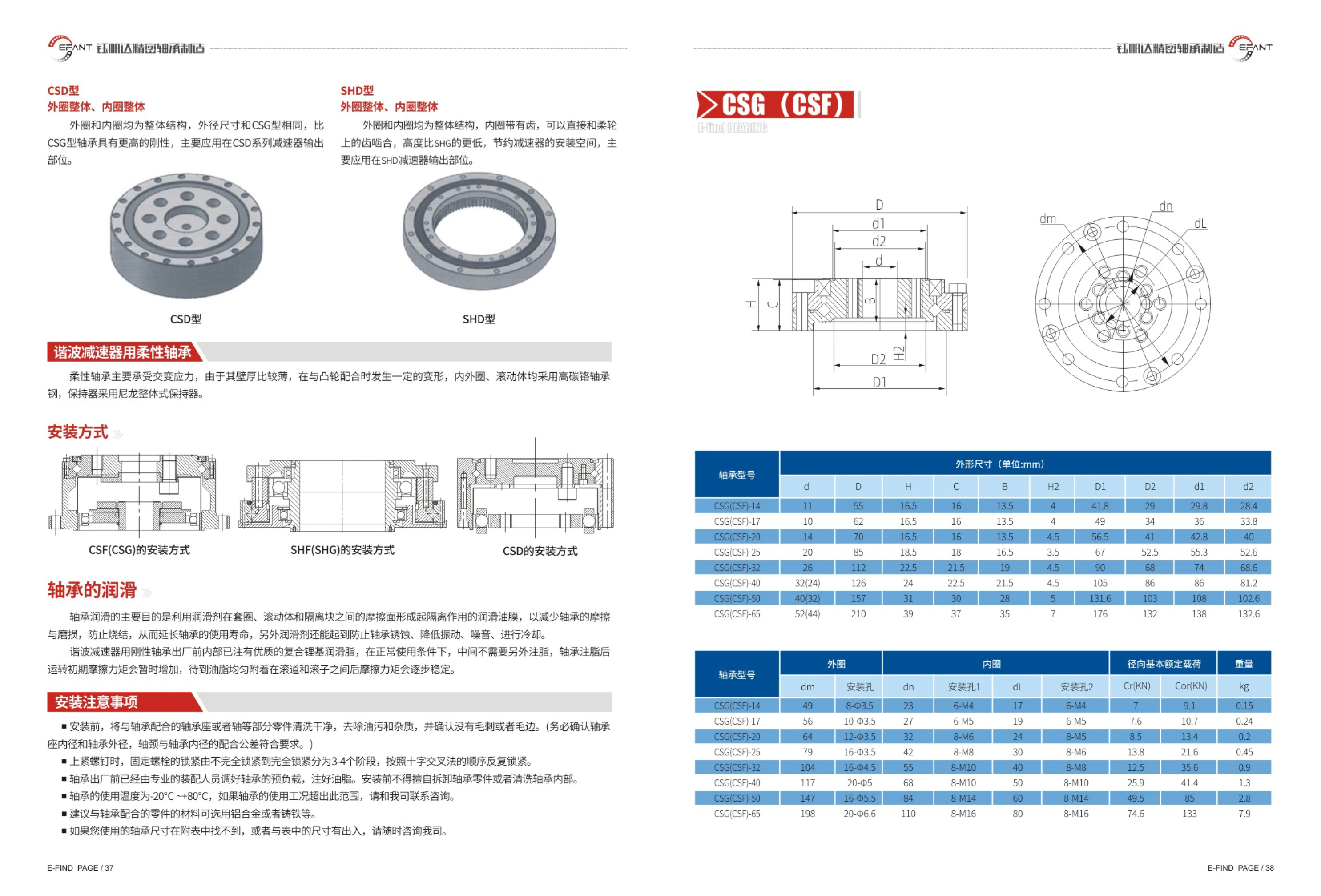
Flexible Bearings for SHD Harmonic Reducers
Flexible bearings for SHD harmonic reducers feature one-piece outer and inner rings. The inner ring has teeth that mesh directly with the teeth on the flexspline. Their lower profile compared with the SHG type saves installation space, and they are primarily used at the output of SHD series reducers. The thin-walled flexible bearing is subject to alternating stress and deforms to a degree when fitted to the cam. The inner and outer rings and rolling elements are made of high-carbon chromium bearing steel, and the cage is a one-piece nylon design. The bearings are filled with high-quality lithium complex grease and preloaded before leaving the factory; no relubrication is required under normal operating conditions. The operating temperature is -20℃~+80℃, and aluminum alloy or cast iron is recommended for mating components. Consult the manufacturer if the required dimensions are not listed in the accompanying table or differ from those shown.
CSG(CSF) Flexible Bearings for Harmonic Reducers
Flexible bearings for harmonic reducers are thin-walled flexible ball bearings designed primarily to withstand alternating stresses. Their thin walls undergo controlled elastic deformation when paired with an elliptical cam, driving the flexspline into periodic meshing engagement. They are core components of harmonic reducers. The inner and outer rings and rolling elements are made of high-carbon chromium bearing steel, while the cage is a one-piece nylon structure. Before shipment, trained assembly personnel adjust the preload and fill the bearing with high-quality lithium complex grease. No relubrication is required under normal operating conditions. Both the outer and inner rings are one-piece structures, and the outer diameter matches that of the CSG type. These bearings are mainly used at the output of CSD series reducers. The same series also includes variants such as the CSD type, which has one-piece inner and outer rings and a toothed inner ring that can mesh directly with the flexspline teeth. It has a lower height and is used at the output of SHD reducers. The bearing operating temperature range is -20℃~+80℃. Aluminum alloy or cast iron is recommended for mating components. Models are classified by reducer frame size (14, 17, 20, 25, 32, 40, 50, 65), with each frame size corresponding to specific dimensions such as d, D and H, and mounting hole positions.
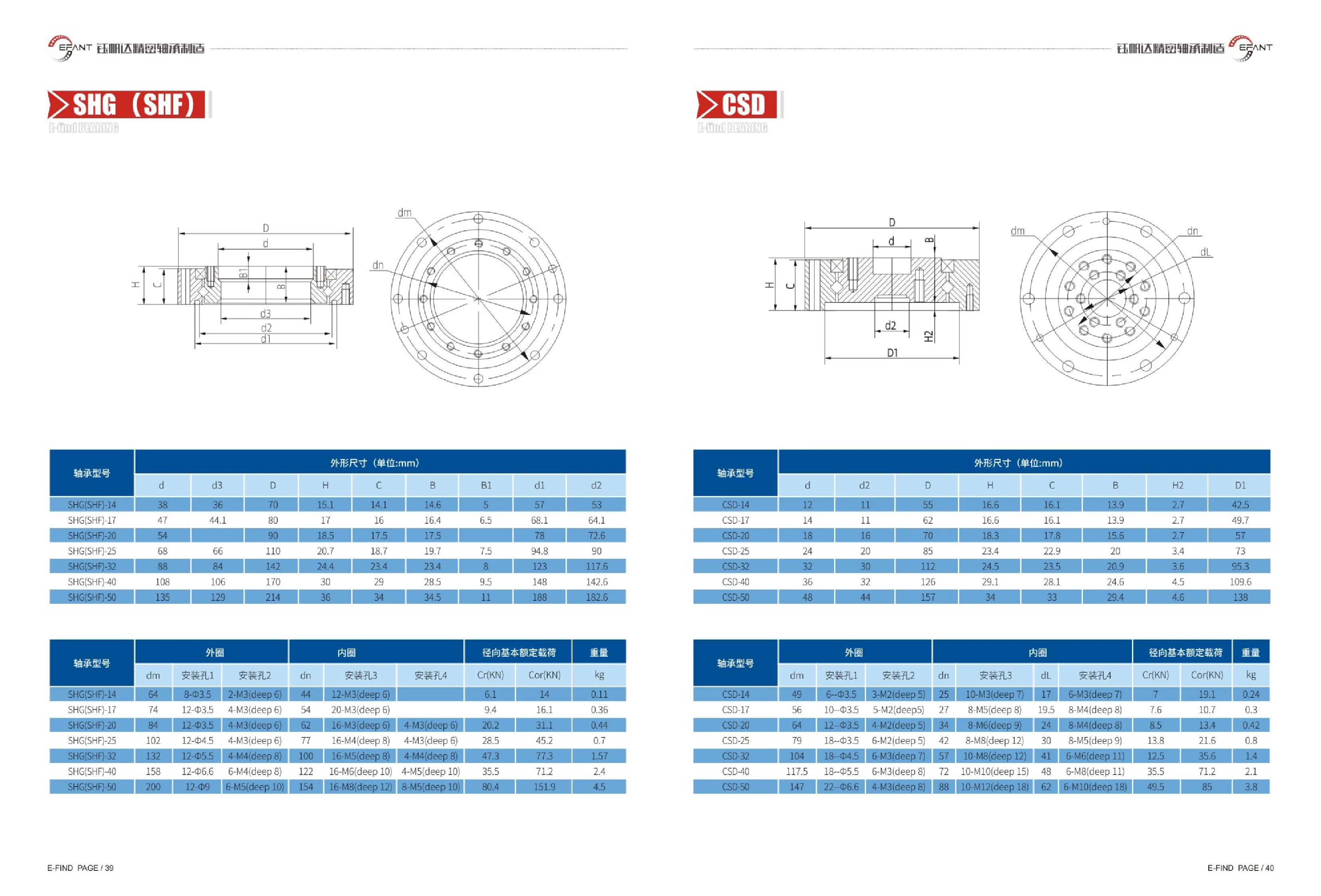
SHG(SHF) Series Crossed Roller Bearings
The SHG(SHF) series comprises thin-section crossed roller bearings in seven sizes: 14, 17, 20, 25, 32, 40, and 50. SHG and SHF models in the same size share the same overall dimensions. The bearing bore diameter d is 38~135mm, the outer diameter D is 70~214mm, and the assembled height H is 15.1~36mm. Mounting and mating dimensions including d3, C, B, B1, d1, and d2 are also provided. The series features a single row of rollers arranged crosswise at 90°, allowing it to support radial, axial, and tilting moment loads simultaneously. It offers high rigidity, high rotational accuracy, and a compact design, and is commonly used for rotary support at harmonic drive outputs, industrial robot joints, precision rotary tables, and semiconductor equipment. When selecting a model, use the size code (14~50) to determine the inner and outer diameters and mounting hole positions. During installation, ensure that the inner- and outer-ring bolts are preloaded evenly.
CSD Series Crossed Roller Bearings
CSD series crossed roller bearings have a thin-walled structure with rollers arranged at 90° to one another and mounting holes integrated into both the inner and outer rings. They offer high rigidity and precision in a space-saving design and can simultaneously support radial loads, axial loads, and overturning moments. The catalog covers 7 sizes from CSD-14 to CSD-50, with inner diameters of 12~48 mm, outer diameters of 55~157 mm, overall heights of 16.6~34 mm, basic dynamic radial load ratings of 7~49.5 kN, static load ratings of 10.7~85 kN, and weights of 0.24~3.8 kg. Applications include industrial robot joints, precision rotary tables, measuring instruments, medical equipment, and semiconductor manufacturing equipment.

XR/JXR Series Crossed Tapered Roller Bearings
XR/JXR series crossed tapered roller bearings use a steep contact angle and tapered geometry to increase the overall effective bearing span. The extended lines of the tapered roller rolling surfaces intersect on the bearing's axis of rotation. The rollers roll without sliding relative to the raceways, resulting in a much higher limiting speed and lower frictional torque than crossed cylindrical roller bearings. Each bearing consists of one outer ring, two split inner rings, crossed tapered rollers and nylon spacers. Line contact between the rollers and raceways allows the bearing to support radial loads, axial loads and high overturning moments simultaneously. A single bearing can replace a conventional bearing assembly, offering a compact cross-section and high rigidity. Adjustable preload extends bearing life and improves rigidity and runout accuracy. The nylon sealing ring has low inertial mass and little effect on operating torque. The finished components are supplied unassembled and installed by the user through alignment and preloading. The gap between the inner rings provides lubrication, and lifting holes in the outer ring simplify installation. Bore diameter: 203.2~1549.4mm; outside diameter: 279.4~1828.8mm; height: 31.75~114.3mm; basic radial dynamic load rating: 51.2~516kN; axial dynamic load rating: 61.4~698kN; limiting speed (oil): 80~800r/mi
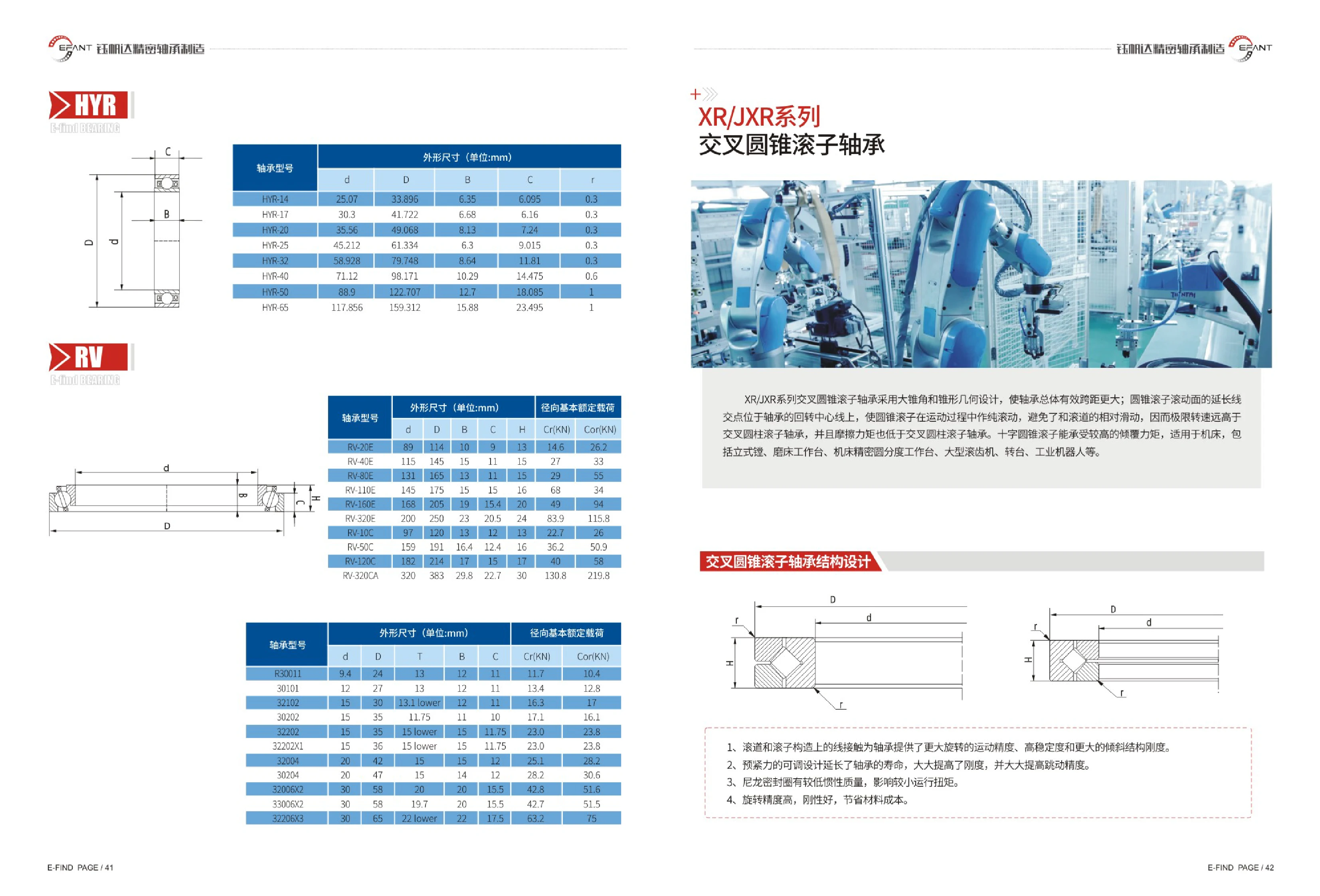
RV Series Crossed Roller Bearings
The RV series of crossed roller bearings is available in three configurations: RV-E, RV-C and RV-CA. Model designations consist of RV followed by a size code, with ten sizes ranging from 20 to 320. These thin-section bearings have rollers arranged at 90° to one another in V-shaped raceways. A single bearing can simultaneously support radial loads, axial loads in both directions and overturning moments. Features include a compact design, high rigidity, high rotational accuracy, low starting friction torque and long service life. The catalog lists the bore diameter d and outer diameter D (in mm) for each model to assist with selection based on available mounting space and the design of mating components. The series is widely used in applications requiring high rigidity and rotational accuracy, including machine tool rotary tables, vertical boring and grinding machine tables, precision indexing tables, large gear hobbing machines, turntables and industrial robot joints. To select a bearing, first determine the size code based on mounting space and load requirements, then choose the final model according to preload, lubrication and sealing conditions.
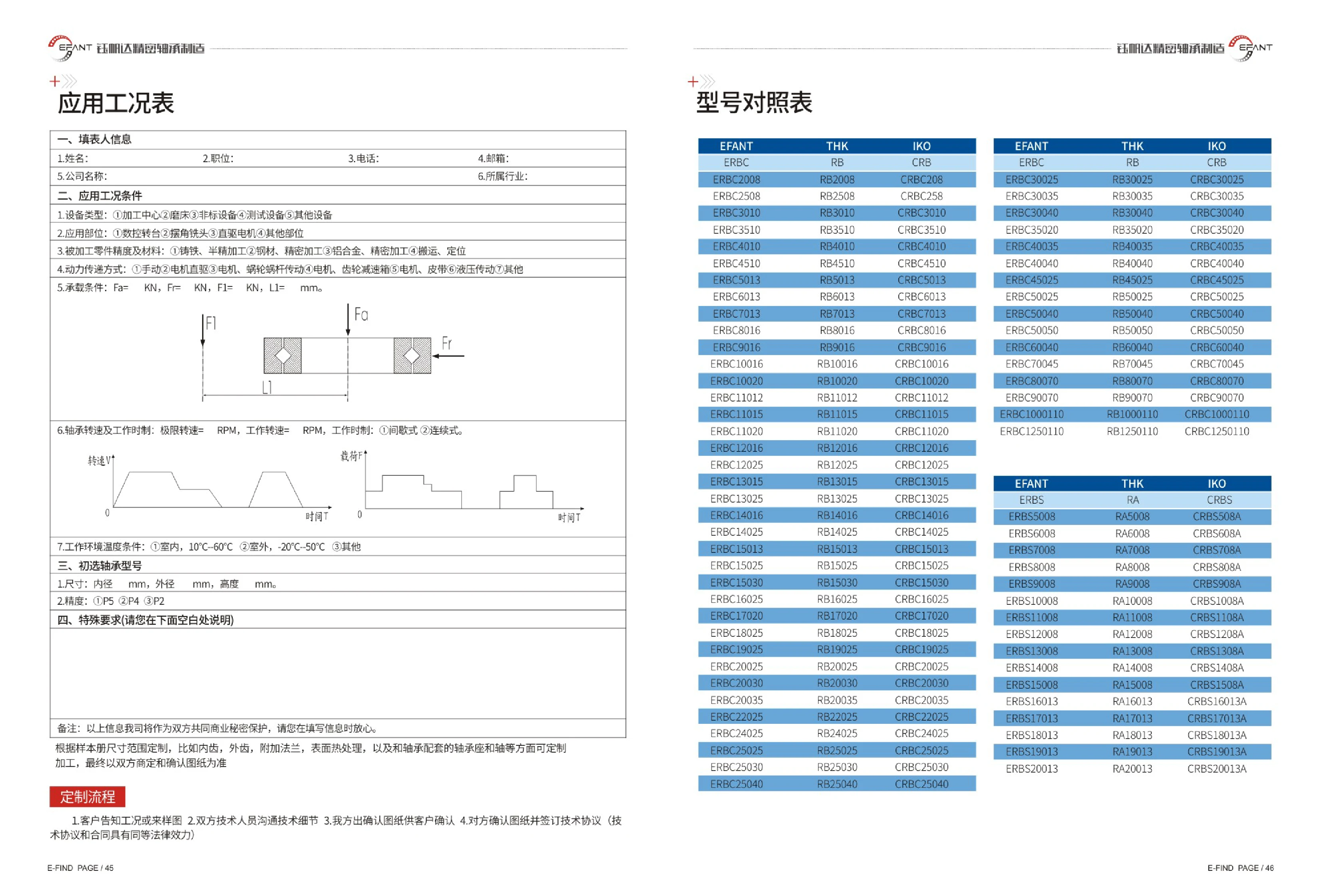
ERBS Series Crossed Roller Bearings
The ERBS series consists of thin-section crossed roller bearings with a single row of rollers arranged alternately at 90°. They can simultaneously support radial loads, axial loads in both directions, and overturning moments, while offering a thin cross-section, high rigidity, and high rotational accuracy. Catalog models are designated as “ERBS+bore diameter+width” and cover bore diameters of 50~200mm. They are available in two width ranges: 8mm (ERBS5008~ERBS15008) and 13mm (ERBS16013~ERBS20013). They correspond to and are interchangeable with the THK RA series and IKO CRBS series. Available accuracy grades are P5, P4, and P2. Typical applications requiring high rigidity and rotational accuracy include CNC rotary tables on machining centers, swiveling milling heads, direct-drive motors, robot joints, and test equipment. In addition to standard models, internal or external gear teeth, additional flanges, surface heat treatment, and matching bearing housings and shafts can be customized to suit operating conditions. Final specifications are subject to drawings approved by both parties.
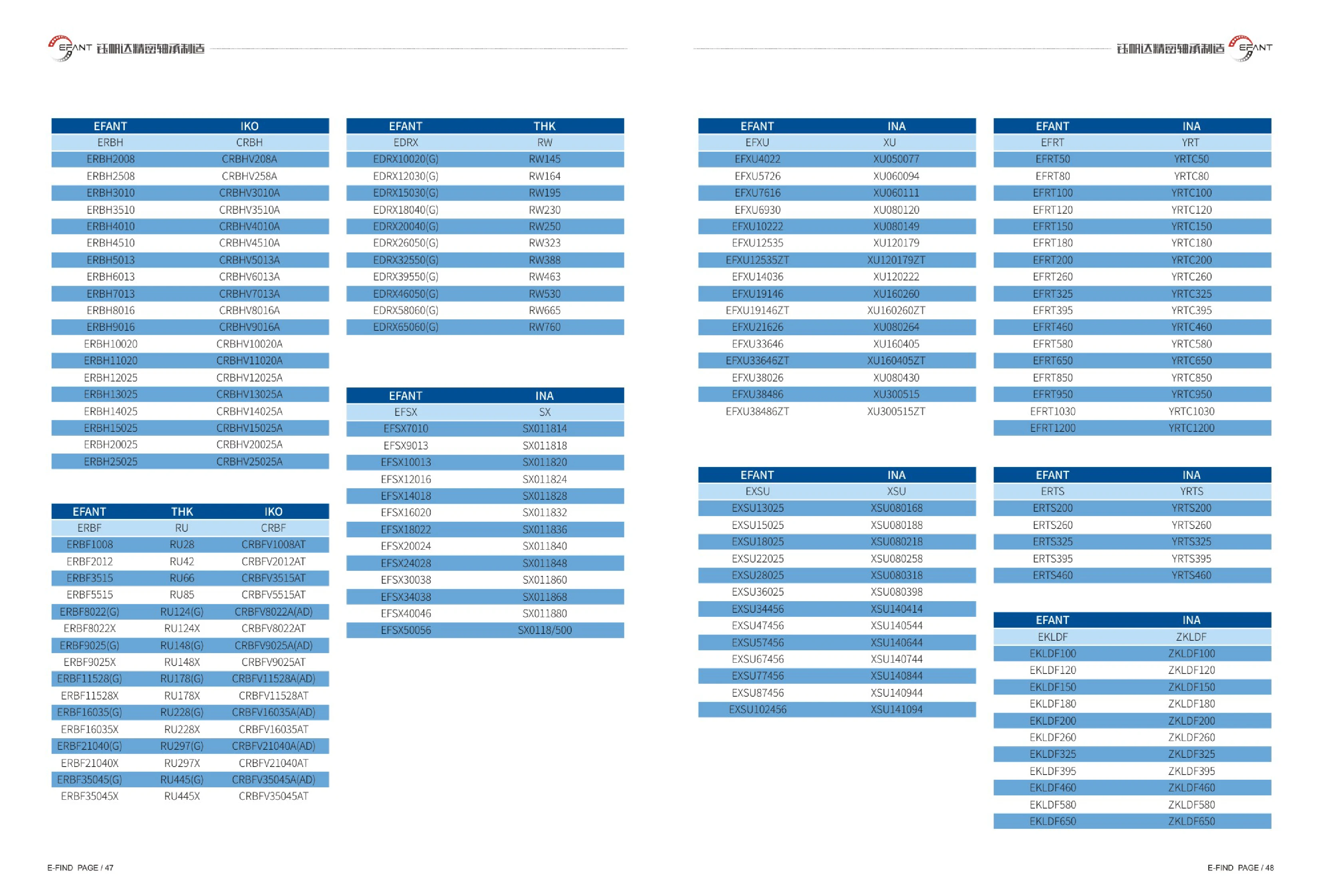
ERBH Series Crossed Roller Bearings
ERBH series crossed roller bearings feature rollers arranged at 90° to one another between the inner and outer rings. A single bearing can simultaneously support radial loads, axial loads in both directions, and overturning moments. They offer a compact design, high rigidity, and high rotational accuracy. The series has an integral inner or outer ring (corresponding to the IKO CRBH/CRBHV series) and requires no additional adjustment shims during installation. It enables highly rigid, precise rotary motion in applications such as robot joints, CNC indexing tables, rotary worktables, precision rotary tables, medical equipment, and semiconductor equipment. The catalog lists models from ERBH2008 to ERBH25025 by bore diameter and width, with bore diameters of approximately 20~250 mm and widths of 8~25 mm. Users can select a model based on available mounting space and load requirements. Corresponding sizes are directly interchangeable with IKO CRBHV bearings.
ERBF Series Crossed Roller Bearings
ERBF series crossed roller bearings feature a compact design with rollers arranged at 90° to one another. They simultaneously support radial, axial and moment loads, offering high rigidity, high rotational accuracy and space-saving installation. They are suitable for robot joints, rotary tables, machine tool indexing tables and precision rotary mechanisms. Model numbers consist of ERBF followed by the bore diameter and width; for example, ERBF1008 has a bore diameter of 10 mm and a width of 8 mm. Some sizes are available in (G) and X variants. The catalog provides a model-by-model correspondence with the THK RU series to simplify selection and replacement.
EFXU Series Crossed Roller Bearings
The EFXU series consists of full-complement crossed roller bearings with rollers arranged alternately at 90° to one another in a 90° V-shaped raceway. They accommodate radial loads, axial loads in both directions, and tilting moments simultaneously. Their high rigidity, high rotational accuracy, and compact axial dimensions make them suitable for rotary positioning applications such as robot joints, CNC indexing tables, machine tool rotary tables, radar, and medical equipment. Corresponding to the INA XU series, these bearings have integral inner and outer rings. Model numbers consist of EFXU followed by a size code, with sizes ranging from small and medium-light models to large models with outside diameters exceeding 400 mm. Some models have a ZT suffix denoting a structural variant. Select the appropriate size based on bore diameter, outside diameter, width, dynamic and static load ratings, and tilting moment. During installation, ensure the mounting surfaces are sufficiently flat and rigid to take full advantage of the bearing's high rigidity.
EXSU Series Crossed Roller Bearings
EFANT EXSU series crossed roller bearings are equivalent to the INA XSU series. Their cylindrical rollers are arranged crosswise at 90°, allowing them to simultaneously withstand radial loads, axial loads in both directions, and tilting moments. They offer high rigidity, high rotational accuracy, and a compact cross-section. The series is suitable for precision rotation applications such as industrial robot joints, machine tool rotary tables, indexing tables, radar, and medical equipment. The catalog lists 13 sizes, from EXSU13025 to EXSU102456, with the corresponding INA XSU model for each to facilitate selection and replacement. During installation, ensure the mating surfaces are accurate and clean, and apply lubrication and preload appropriate to the operating conditions.
EKLD Series Crossed Roller Bearings
EKLD series crossed roller bearings are EFANT bearings designed specifically for rotary tables. The catalog provides a model cross-reference showing the corresponding INA ZKLDF series specification for each model. Featuring a crossed-roller/multi-row rolling element design, these bearings can simultaneously support axial loads, radial loads, and tilting moments. They are suitable for applications requiring high rigidity and rotational accuracy, including CNC rotary tables, indexing tables, rotary tables in vertical and horizontal machining centers, and rotary joints in radar and medical equipment. The number in each model designation indicates the bearing bore diameter. The range covers bore diameters from 100 mm to 650 mm in 11 sizes: EKLD100, EKLD120, EKLD150, EKLD180, EKLD200, EKLD260, EKLD325, EKLD395, EKLD460, EKLD580, and EKLD650. Select a model according to the rotary table bore diameter, load capacity, and speed requirements. During installation, ensure the mounting surfaces meet flatness and fit accuracy requirements. For dimensions, load ratings, and limiting speeds, refer to the dimension table for the corresponding INA ZKLDF size.
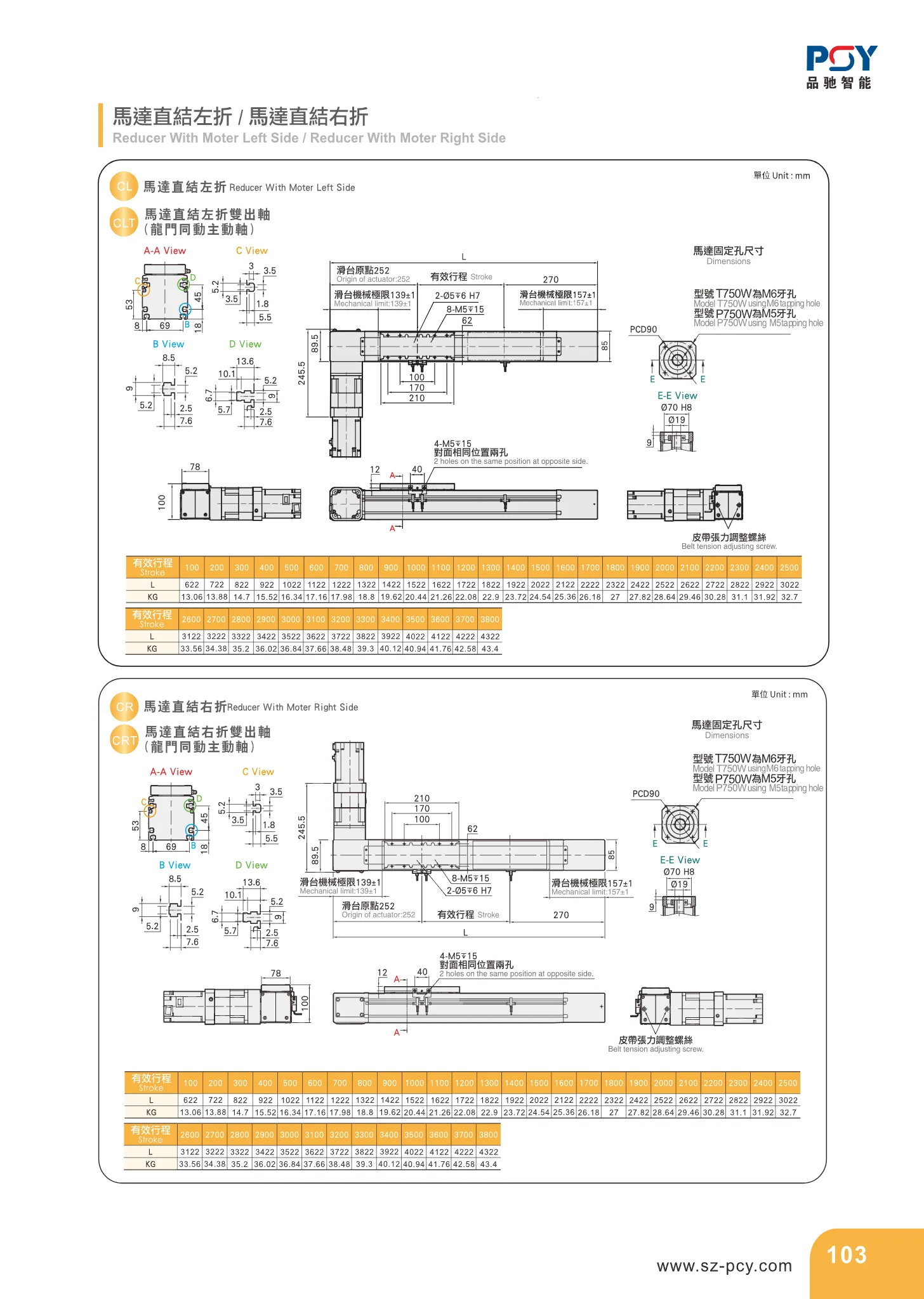
Direct-Mount Motor Gearbox, Left/Right Output
This direct-mount motor gearbox connects directly to the motor and is available in left-output and right-output versions. The left-output version has its output shaft facing left, while the right-output version has its output shaft facing right. It changes the direction of power transmission by 90° in limited installation spaces and is commonly used between motors and loads in automated equipment. When selecting a gearbox, check the motor flange specifications, reduction ratio, rated output torque, permissible radial and axial loads, backlash, lubrication method, and installation orientation (left or right). This catalog page only compares the two configurations; refer to the corresponding specification tables for reduction ratios, torque ratings, flange dimensions, and overall dimensions. During installation, pay attention to motor-to-gearbox alignment, tightening torque, grease grade, and the permissible operating temperature range.
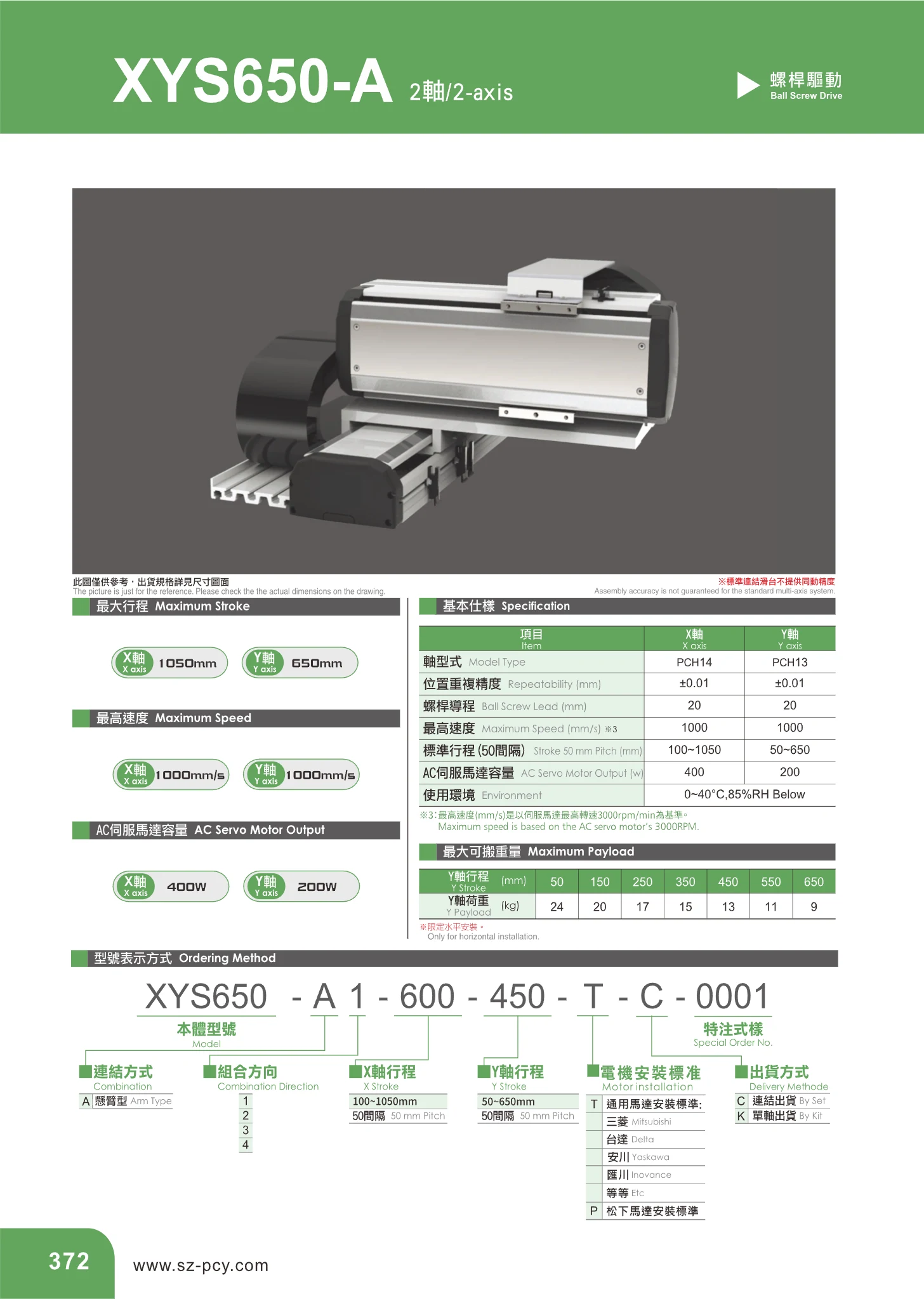
PCH Series Two-Axis Linear Modules
The PCH series consists of two-axis (X-Y) linear modules with a cross-slide structure, combining an X axis and a Y axis. Driven by ball screws and AC servo motors, they are suitable for two-dimensional positioning, material handling, dispensing, and inspection in automated equipment. The X-axis model is PCH14 and the Y-axis model is PCH13. Both axes have a positioning repeatability of ±0.01 mm, a ball screw lead of 20 mm, and a maximum speed of 1000 mm/s. Stroke lengths are available in 50 mm increments: the standard stroke range is 100~1050 mm for the X axis (PCH14) and 50~650 mm for the Y axis (PCH13). The corresponding AC servo motor ratings are 400 W for the X axis and 200 W for the Y axis. Operating conditions are 0~40 °C and below 85%RH. Users can select strokes in 50 mm increments within each axis's range and freely combine X and Y axes to create two-axis modules in different configurations.

YKK Series Single-Axis Robots
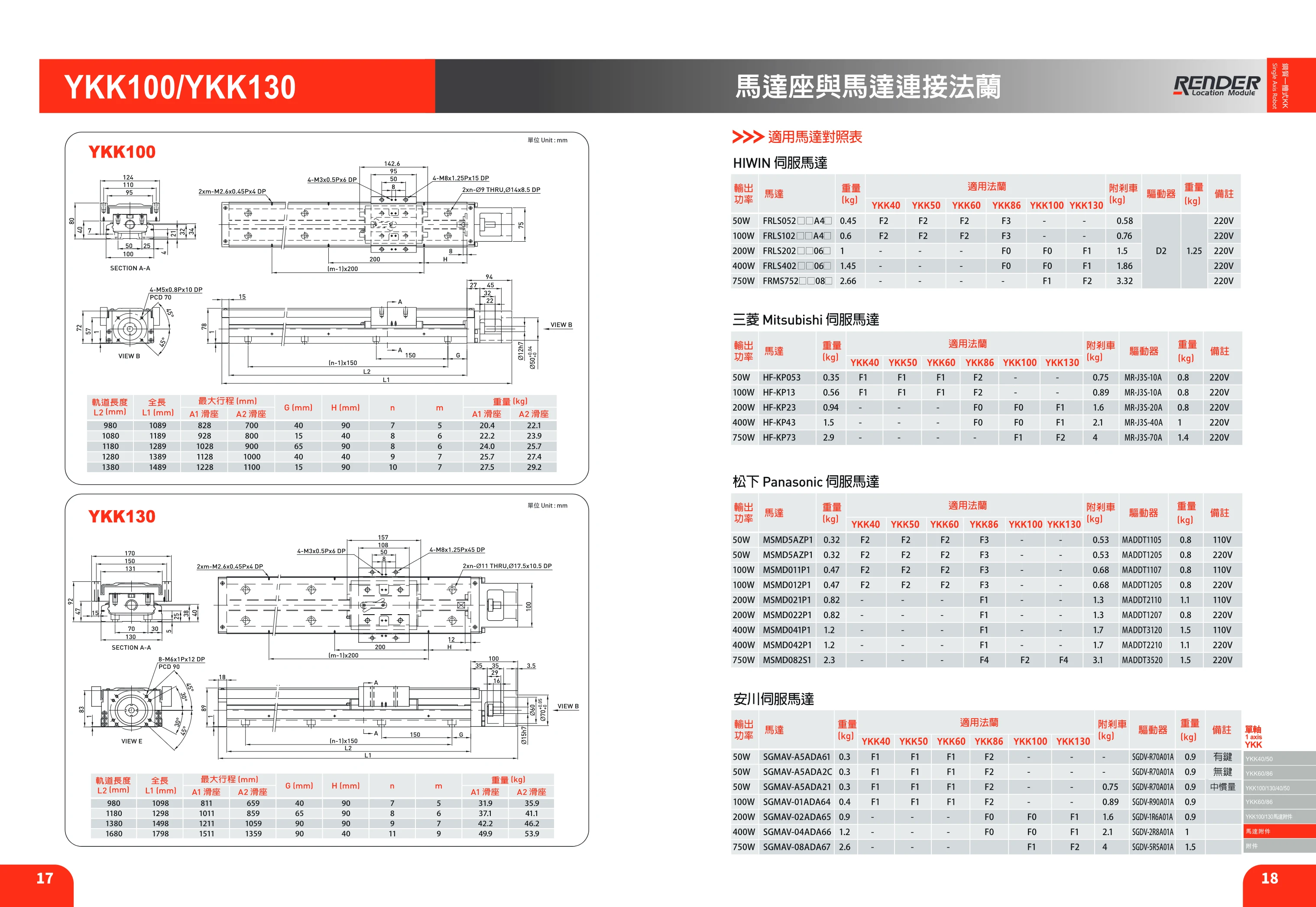
YKK series single-axis robots feature a modular design that integrates a ball screw and linear guide rail. They offer high precision, quick installation, compact size, light weight, space savings, and high rigidity. The U-shaped rail is optimized through finite element analysis, and the carriage and rail use a two-row Gothic arch profile with a 45° contact angle to support equal loads in four directions. The range includes YKK40, YKK50, YKK60, YKK86, YKK100, and YKK130 models, with cross-sectional widths of 40~130 mm and heights of 20~65 mm. They are suitable for automated equipment requiring precise linear motion and compact installation.

YKK Series Single-Axis Robots
YKK series single-axis robots (linear modules) use ball screw drives and are available in six cross-section sizes: 40, 50, 60, 86, 100 and 130. They support various leads, precision or standard accuracy grades, and a range of rail lengths. Optional aluminum covers, telescopic protective covers, motor mounting flanges and limit switches provide protection against dust and debris, expand motor interface options, and enable carriage positioning, homing and overtravel protection. Special machining, designated E, is available for the ball screw and rail. Grease is recommended for lubrication, with speed limited to 60 m/min. Replenish grease through the carriage grease fitting at the specified intervals; fitting specifications vary by model. Selection should take into account size, lead, accuracy, rail length and motor flange compatibility.
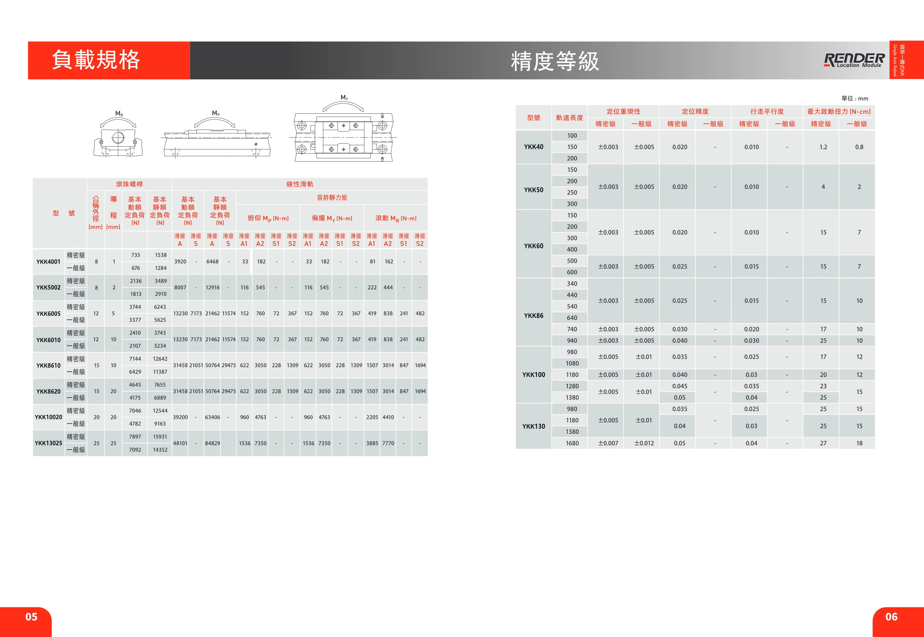
YKK Series Linear Modules
The YKK series consists of semi-enclosed ball screw linear modules that integrate an aluminum extrusion base, precision ball screw, linear guide, coupling, and sensor mounting slots. They are designed for precision linear transfer, positioning, and pushing operations in automated equipment. Standard models include six cross-sectional sizes: YKK40, YKK50, YKK60, YKK86, YKK100, and YKK130. Track lengths are available in increments from 100mm to 1680mm. Maximum stroke varies by model and track length (for example, the YKK40-100 has a maximum stroke of 35mm, while the YKK100-1380 has a maximum stroke of 1346mm). Positioning repeatability is ±0.003~±0.007mm, positioning accuracy is ±0.005~±0.012mm, and travel parallelism is 0.020~0.05mm; accuracy decreases slightly as track length increases. The body includes mounting slots for limit switches and can be fitted with sensors such as the Omron EE-SX671 and PANASONIC GX-F12A / GX-F12A-P for home and limit detection at both ends of travel.
HIWIN Servo Motors
The HIWIN servo motor series is designed for use with drive components such as linear modules and single-axis robots. The catalog provides a compatible motor reference table organized by output power: 50W, 100W, 200W, 400W, and 750W. For each rating, it lists the HIWIN motor model (FRLS052, FRLS102, FRLS202, FRLS402, or FRMS752), motor weight, compatible flange code (F0/F1/F2/F3/F4), compatible flange code when a brake is fitted, matching drive and its weight, and voltage rating (110V or 220V). The same table also lists models, weights, and compatible flanges for motors in the same power ranges from international brands such as Mitsubishi (HF-KP series), Panasonic (MSMD series), and Yaskawa. This makes it easy to match power ratings and flange interfaces when changing drive or motor brands. To select a motor, first determine the required power based on the mechanism load, then check the module flange code and whether a brake is needed, and finally match the drive model and supply voltage.
Servo Motors for Linear Modules
This reference table covers servo motors compatible with linear modules from brands including HIWIN, Mitsubishi, Panasonic and Yaskawa, with output power from 50W~750W. Selection information includes compatible flanges, brake options, drive models and weights, and 110V/220V voltage ratings. Select the appropriate motor and drive according to the linear module specifications, ensuring compatibility with the mounting flange and brake configuration. Note that the Yaskawa table duplicates the Panasonic data, possibly due to an OCR error, and is not listed separately.
Servo Motor Flange Compatibility Chart
This page provides a flange compatibility chart for servo motors used with linear modules. Organized by output power (50W, 100W, 200W, 400W, 750W), it lists servo motor models from HIWIN, Mitsubishi, Panasonic and Yaskawa, along with motor weight, compatible flange codes (F0, F1, F2, F3, F4), flange codes and additional weight for motors with brakes, matching driver models and weights, and supply voltages (110V/220V). Users can select a flange code based on motor power and brand, allowing the same linear module to be fitted with servo motors of different brands and power ratings. Note that the models and specifications in the Yaskawa column of the source exactly duplicate those in the Panasonic column, likely due to a catalog layout or copying error. Verify models and weights against the motor manufacturer's documentation when selecting a motor.
SYX-H-BN Series Linear Guide Rails
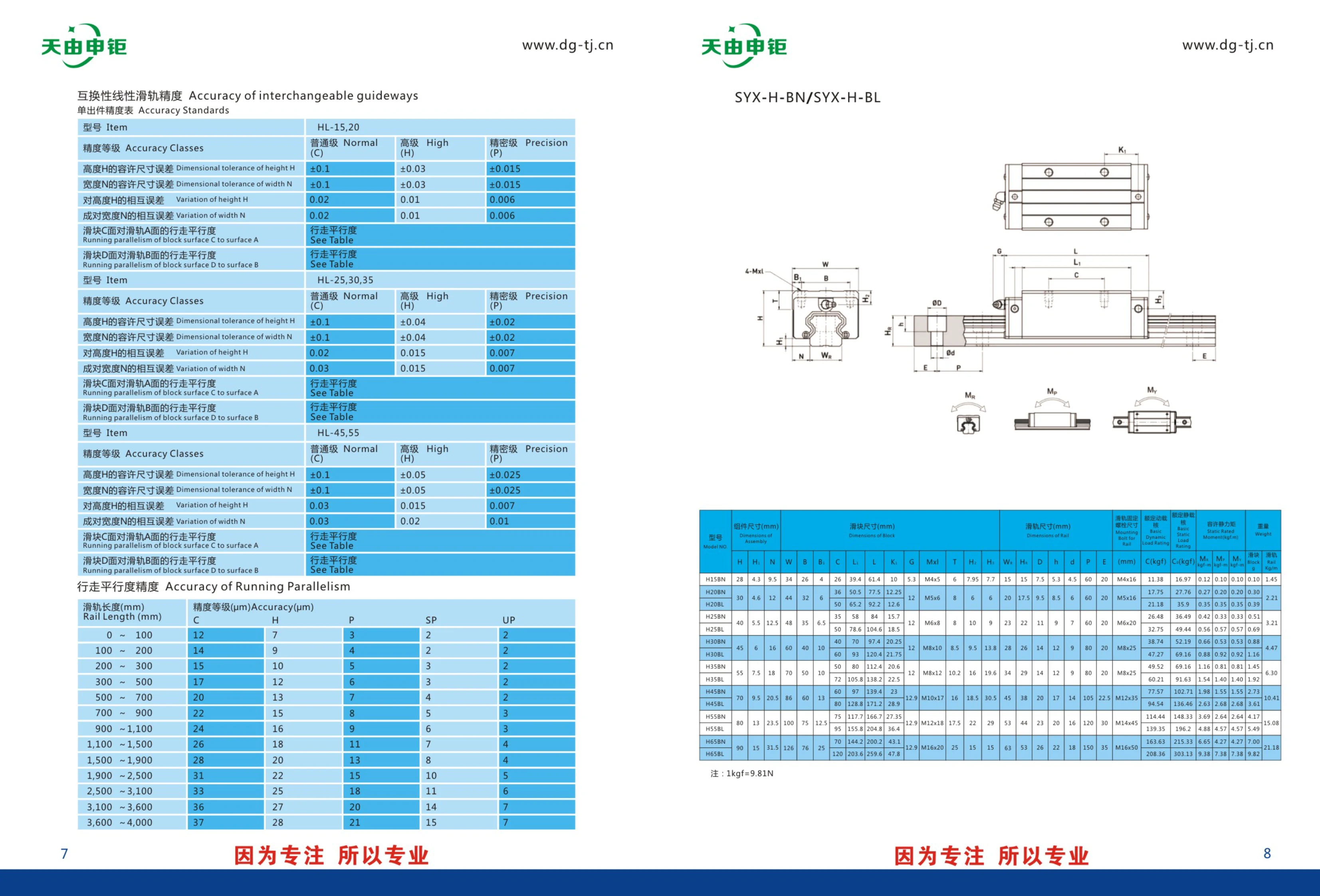
The SYX-H-BN/SYX-H-BL series linear guide rails include models HL-15, HL-20, HL-25, HL-30, HL-35, HL-45, and HL-55. Available in three accuracy grades—Normal (C), High (H), and Precision (P)—they have specified dimensional tolerances and matching tolerances for different heights (H) and widths (N). Suitable for automation equipment, machine tools, and other applications requiring high-precision linear motion.

Miniature Compression Force Sensor
This series of miniature compression force sensors uses a high-precision resistive strain gauge design. Made of stainless steel with a sealed, welded construction, the sensors resist oil, water, and corrosion. Their covered-disc/diaphragm capsule design supports compression loading and offers easy, flexible installation. Benefits include a low profile, minimal deformation, compact dimensions, and high dynamic response frequency. Rated capacities range from 50~500N, with an output sensitivity of 1.5±15%mV/V and a safe overload of 120%F.S. Applications include automotive press-fitting, automated assembly, 3C product testing, new energy product assembly, medical testing, mold assembly in robotics, and other industrial testing, measurement, and control systems.
Miniature Force Sensors
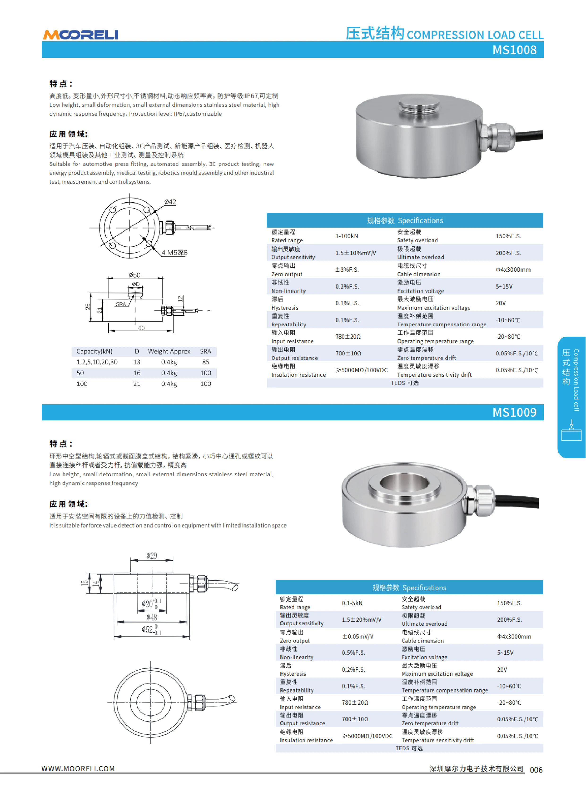
Miniature force sensors feature a stainless steel sensing element, a low profile, compact dimensions and minimal deformation under load, making them suitable for force measurement where installation space is limited. They measure both tension and compression, offer a high dynamic response frequency and provide overload protection. Some models have an IP67 protection rating, and customization is available to suit operating conditions. Typical specifications include rated capacity, safe overload, output sensitivity and insulation resistance. Capacities range from very small forces to medium and high loads, with output options available to suit compatible instruments. Applications include force gauges, injection molding and tooling, robotic gripping and press-in force measurement, automotive press-fitting and assembly force measurement, automated assembly, 3C product testing, new energy product assembly, medical testing, and a wide range of industrial testing, measurement and control systems.

Hollow Ring Force Sensors
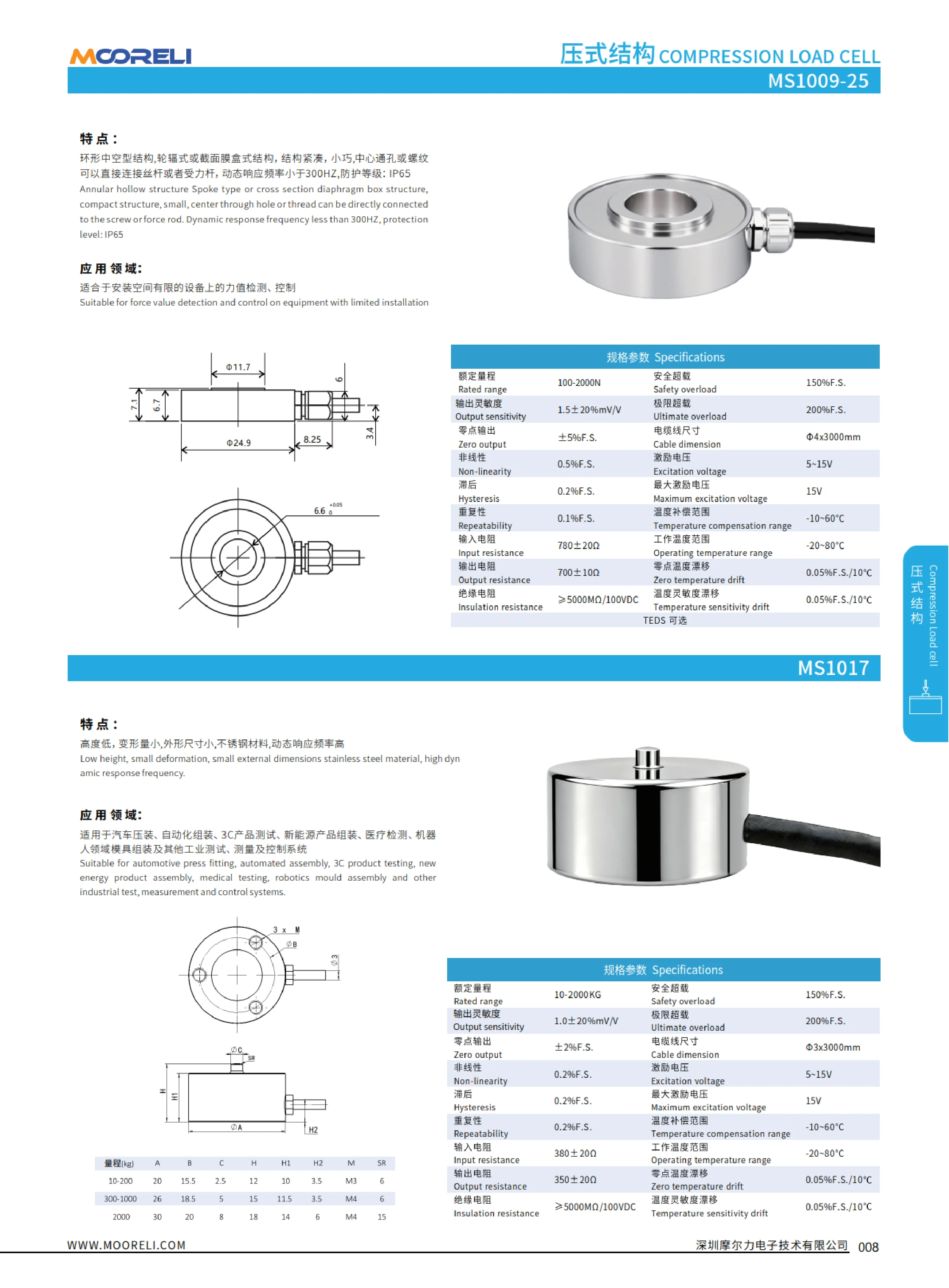
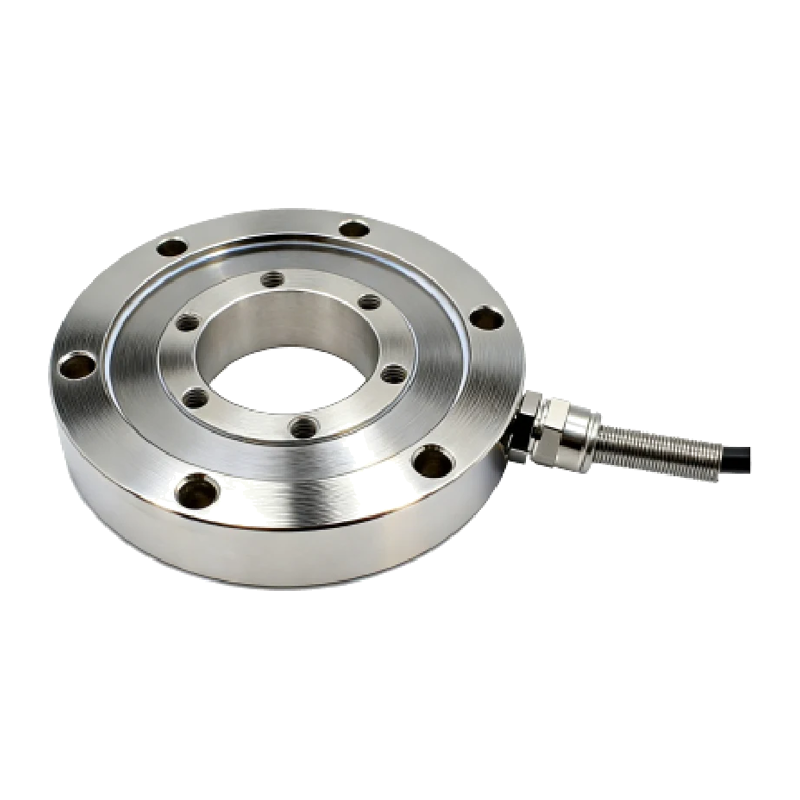
Hollow ring force sensors feature a compact annular design, with spoke-type or waisted-disc cross-section structures. A central through-hole or thread allows direct connection to a lead screw or load rod. Designed for force measurement and control in equipment with limited installation space, these sensors offer a low profile, minimal deformation, compact dimensions, stainless steel construction, and a high dynamic response frequency. They are rated IP65, with a dynamic response frequency below 200Hz (the English text in the original specifies below 300Hz). Applications include automotive press-fitting, automated assembly, 3C product testing, new energy product assembly, medical testing, robot model assembly, and other industrial testing, measurement, and control systems. Specifications include rated load, safe overload, output sensitivity, ultimate overload, zero-point sensitivity, and temperature sensitivity.
Low-Profile Force Sensors
The low-profile force sensor series includes annular hollow and low-height spoke-type or waisted-disc designs. Made of stainless steel, these sensors are compact, small in size, and exhibit minimal deformation. A central through-hole or thread connects directly to a lead screw or force-bearing rod. They offer a high dynamic response frequency (less than 200Hz in the original text, 300Hz on the English page) and an IP65 protection rating. They are suitable for force measurement and control in equipment with limited installation space, as well as industrial testing, measurement, and control systems used in automotive press-fitting, automated assembly, 3C product testing, new energy product assembly, medical testing, and robot model assembly.
Hollow Ring Force Sensors
Hollow ring force sensors use a spoke-type or cross-section spiral (diaphragm-type) elastic element. Their compact, low-profile design features a central through-hole or thread that connects directly to a lead screw or load rod, allowing the sensor to be integrated into a drive train for force measurement in press-fitting and tension/compression testing. The dynamic response frequency is less than 200Hz (the original English text states less than 300Hz). With an IP65 protection rating, the sensors operate reliably in typical industrial environments exposed to dust and water splashes. Applications include automotive press-fitting, automated assembly, 3C product testing, new energy vehicle assembly, medical testing, robotics and module assembly, as well as other industrial testing, measurement and control systems. Key selection criteria include capacity, central through-hole or thread size, overall dimensions, output signal and protection rating.

Load Cells
This series of resistance strain gauge load cells (force sensors) uses aluminum alloy, alloy or stainless steel sensing elements. Features include high accuracy, strong resistance to off-center loading, easy installation, excellent long-term stability and high ingress protection ratings (IP65~IP68). Some designs can replace existing shafts, and sizes and shapes can be customized. Key specifications include rated capacity (including low capacities such as 50-500g), accuracy class C3, rated output 1.0±10%mV/V, zero output ±2%F.S., nonlinearity 0.01%F.S., output resistance 1.0±10%mV/V, safe overload 150%F.S., ultimate overload 300%F.S., temperature compensation range 10-60℃, IP65/IP68 protection ratings and cable dimensions. Wiring: EXC+ red, EXC- black, SIG+ green, SIG- white, with the shield wire grounded. Applications include electronic scales, weighbridges, hopper scales, testing machines, insertion and extraction force and button testing, robotic gripping, injection molding and mold manufacturing, new energy product assembly, automated assembly, cargo weighing at ports and terminals, safety testing of lifting equipment, and force measurement systems in the semiconductor industry.

Round Compression Force Sensor
The round compression force sensor uses a high-precision resistance strain gauge principle and features a stainless steel sensing element with a welded seal. It is resistant to oil, water and corrosion, making it suitable for long-term use in humid, dusty and other challenging environments, including hazardous locations. Its round design is intended primarily for compression loading, with minimal deformation under load, a high dynamic response frequency (≥22KHZ), high stiffness and strong resistance to off-center loads. It is compact, attractive and easy to install and use. Some models support bidirectional tension and compression measurement, allowing both forces to be detected. Typical specifications include rated capacity, output sensitivity, nonlinearity, repeatability, hysteresis, zero temperature drift, input/output impedance, insulation resistance, recommended excitation voltage, safe and ultimate overload, operating temperature range, protection rating, cable length and cable exit configuration. These sensors are primarily used for force measurement and process control in industrial automation applications such as automotive press fitting, automated assembly, consumer electronics testing, new energy product assembly, medical testing, robotics and mold assembly.

Tension and Compression Force Sensor
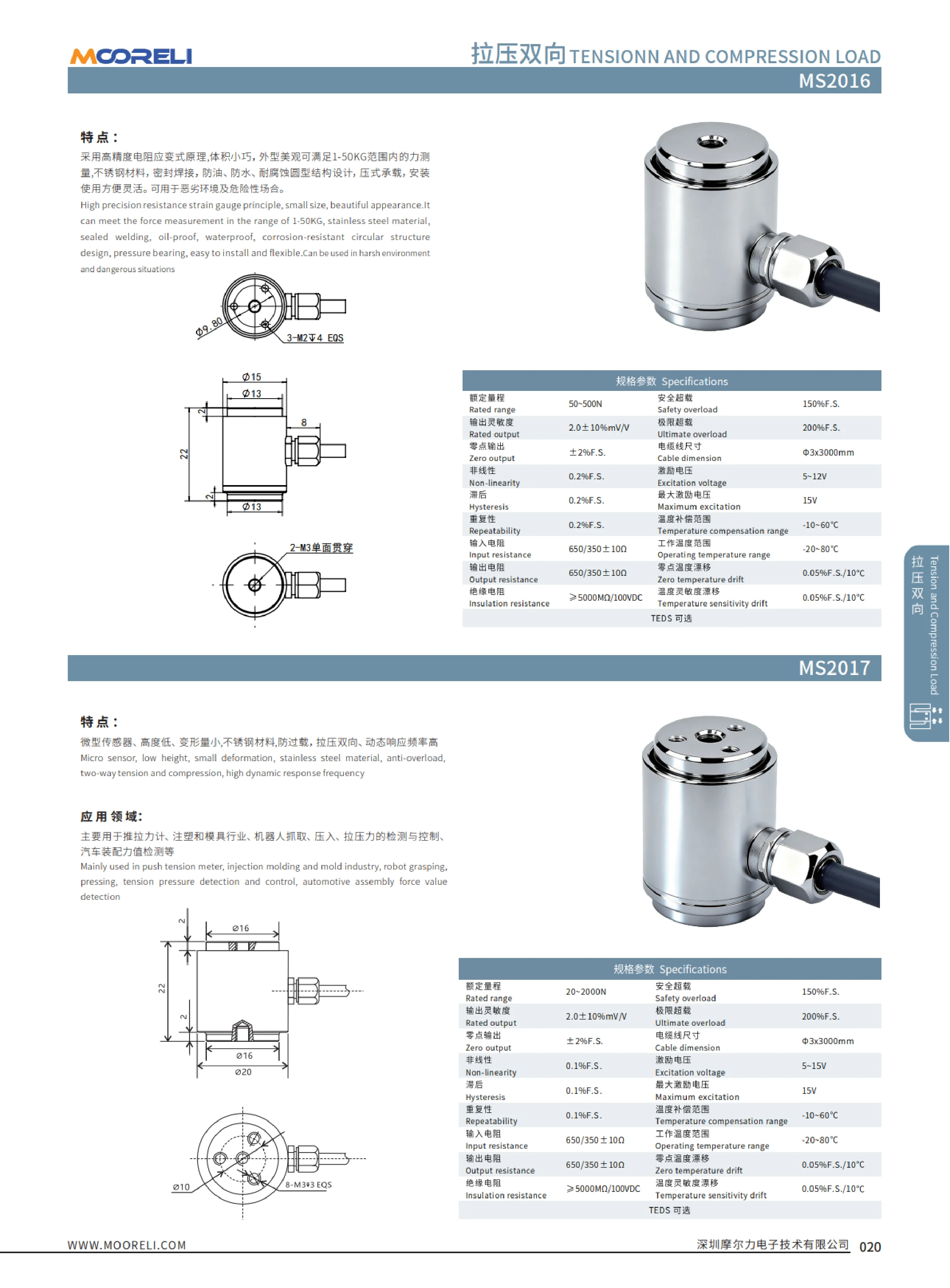
This tension and compression force sensor measures force in both directions. Made of stainless steel, it has a low profile, minimal deformation under load, and an IP65 protection rating for long-term stable operation in demanding industrial environments with dust and moisture. Its rated load range is 50~2000N, with an output sensitivity of approximately 2.0±10% mW/V, a safe overload capacity of 150%F.S., and a temperature drift of approximately 0.025%F.S./10℃. It is suitable for high-precision measurement and closed-loop control of tensile and compressive forces. Typical applications include automotive press-fitting, automated assembly, 3C product testing, new energy product assembly, medical testing, robotics and mold assembly, and other industrial testing, measurement, and control systems. Select a model based on the direction of force, rated load, available installation height, and output signal of the matching amplifier.

Tension and Compression Force Sensor
This stainless steel tension and compression force sensor features a low profile, minimal deformation, and a high dynamic response frequency. It measures both tensile and compressive forces. Its rated capacity is 50-100N, with an output sensitivity of 2.0±10%mN/V, a safe overload of 150%F.S., and an ultimate overload of 200%F.S. Applications include push-pull force gauges, 3C product testing, medical testing, tension control in CNC wire-cutting machines, robotics, and automated testing and measurement. It meets the need for high-precision force measurement in confined spaces with fast response times.
Strain Gauge Force Sensor
This series uses a high-precision strain gauge design in a compact, attractive housing to measure forces from 1~50KG. The stainless steel sensing element is hermetically welded, with a sealed design that resists oil, water and corrosion. Compression loading allows flexible, convenient installation and reliable operation in harsh and hazardous environments. Applications include push-pull force gauges, injection molds, robotic gripping and pressing force monitoring and control, and automotive assembly force measurement. The sensors are suitable for continuous tensile and compressive force measurement and process control. When selecting a model, consider the measuring range (1~50KG), loading direction (compression), mounting interface and output signal type.

MS Series Tension and Compression Sensors
The MS series of tension and compression sensors includes the MS2018 miniature sensor and the MS2019 spoke-type sensor, designed to measure both tensile and compressive forces. Made of stainless steel, the MS2018 features a low profile, minimal deformation, overload protection and a high dynamic response frequency. It is suitable for push-pull force gauges, injection molding and mold applications, robotic gripping and press-in force measurement, and automotive assembly force measurement. The MS2019 has a spoke-type design and is made of alloy steel or stainless steel. Its capacity range is 0.1~300T, with other ranges available on request. It is used in testing machines, truck scales, hopper scales and various industrial weighing systems. The series has a typical output sensitivity of 2.0±1%mV/V, nonlinearity of 0.03%F.S. and high insulation resistance, making it suitable for dynamic and static force measurement and control.

Spoke-Type Load Cell Module Assembly
The spoke-type load cell module assembly is a modular component for industrial weighing and force measurement. Made of alloy steel or stainless steel, it supports both tension and compression loads and is suitable for testing machines, truck scales, hopper scales, and other industrial weighing systems. Its modular design simplifies installation, replacement, and system integration, while different measuring ranges can be customized to suit operating conditions. The assembly is compact, provides stable load-bearing performance, and offers good resistance to off-center loads. It is commonly used for force transmission and weighing applications. When selecting a model, confirm the rated capacity, material, loading direction, and mounting interface to ensure compatibility with the weighing system.

Miniature Spoke-Type Load Cell
The miniature spoke-type load cell (also known as a spoke-type weighing sensor or force-measuring module) is a force measurement device based on a spoke-shaped elastic element. Made from alloy steel or stainless steel, it measures both tension and compression. Its small, compact design offers good resistance to off-center loading and effective sealing, allowing it to be integrated directly into the loading mechanism of a testing machine or into various weighing support points. Capacity can be customized to user requirements (the catalog does not provide a specific capacity table but notes that other capacities are available). Typical applications include materials testing machines, truck scales, hopper scales, and industrial weighing and force measurement systems. The load cell is secured using a central threaded hole and peripheral flange holes, and the load axis must align with the sensor axis. Its strain-gauge bridge signal output can connect to weighing indicators or data acquisition systems. Key selection criteria include rated load, accuracy class, output sensitivity, material (alloy steel/stainless steel), protection rating, and mounting interface dimensions.

MS Series Tension and Compression Sensors
The MS series of tension and compression sensors includes models such as the MS2025 and MS2029. Made from stainless steel or aluminum alloy, they measure both tensile and compressive forces and feature low deformation, high dynamic response frequency and high accuracy. The MS2025 is suitable for force gauges, automated assembly testing, medical testing, robotics and force measurement in industrial automation. The MS2029 has a miniature design with overload protection and is commonly used for button force and insertion and extraction force testing of 3C products, medical testing, and industrial measurement and control systems. The catalog lists parameters including rated capacity, output sensitivity, insulation resistance, safe overload, ultimate overload, compensated temperature range, operating temperature range, zero temperature drift, sensitivity temperature drift and optional TEDS. Specific values should be confirmed for each model.

Miniature Tension and Compression Load Cell
Made of aluminum alloy or stainless steel, this miniature tension and compression load cell features a low-profile design and minimal deformation, enabling bidirectional force measurement. Its rated capacity ranges from 10 to 500N, with a safe overload of 150%F.S., an ultimate overload of 200%F.S., temperature sensitivity of 0.1%F.S./10℃, and zero offset of 0.05%F.S. It is suitable for force gauges, automated assembly, 3C product testing, and other industrial force measurement systems.

Spoke-Type Load Cell
This spoke-type load cell features an alloy steel or stainless steel sensing element and measures both tension and compression. It is suitable for testing machines, truck scales, hopper scales, platform scales, and a wide range of industrial weighing and force measurement systems. Rated capacities range from 5~20t, with C2 and C3 accuracy classes, an output sensitivity of 2.0±0.002mV/V, and a zero balance of ±1%F.S. Nonlinearity, hysteresis, and repeatability can each reach ±0.02%F.S. Other capacities can be customized to meet application requirements.

MS Series Single-Point Load Cells
The MS series consists of single-point (parallel-beam) load cells made from aluminum alloy. They offer high accuracy, strong resistance to off-center loading, and a simple design for easy installation. With an IP65 protection rating, they operate reliably in dusty environments and where exposed to splashing water. These load cells measure weight at a single loading point and are insensitive to shifts in load position, making them suitable for platform scales and compact weighing devices. Typical applications include in-line weighing and metering in dispensing and liquid filling equipment, electronic scales, counting scales, electronic balances, and various industrial weighing and batching systems. The models listed in the catalog are MS3002 and MS3003. Both share the same material, accuracy, off-center load resistance, and protection characteristics; their main differences are physical dimensions and rated capacity. Select the appropriate model using the relevant specification table, taking into account rated capacity, combined accuracy, sensitivity, creep, input and output impedance, and mounting hole dimensions.