product — Page 75

TWH Series Stopper Cylinders
TWH series stopper cylinders are pneumatic actuators used to stop and position workpieces at stations on automated conveyor and assembly lines. The piston rod or stop block extends to stop workpiece pallets or positioning fixtures, controlling the production cycle and holding workpieces in place. The catalog provides parameters including model, specifications, bore, stroke, operating type, weight and overall dimensions. When selecting a cylinder, determine the bore and stroke based on the combined weight of the workpiece and pallet, conveyor speed and available mounting space. Also confirm the operating type (such as single-acting or double-acting, normally closed or normally open) and mounting method. The specification table on this page contains repeated fields and missing values following scan recognition. Refer to the complete catalog or the manufacturer's technical documentation for exact bore sizes, strokes, overall dimensions and weights.

TWG Series Stopper Cylinders
TWG series stopper cylinders are pneumatic actuators used to block, position, or stop workpieces on automated conveyor and assembly lines. The series offers a range of bore sizes, strokes, and operating modes, including single-acting and double-acting options, to suit different load and cycle-time requirements. Typically mounted beside or below the line, the cylinder extends its piston rod to stop a workpiece and retracts it to let the workpiece pass. Compact, fast-responding, and impact-resistant, these cylinders are widely used on automated production lines in the automotive, electronics, logistics, and other industries.

RQ Series Compact Cylinder with Air Cushioning
The RQ series is a compact, flat-profile pneumatic cylinder with an integrated air cushion that absorbs impact and reduces noise and vibration at the end of the stroke. It is suitable for clamping, pressing, lifting, and positioning applications where installation space is limited and smooth stopping is required. The series designation is RQ, with mounting options including B (through-hole, standard) and L. Bore sizes are 20, 25, 32, 40, 50, 63, 80, and 100 mm; the stroke is selected to suit the application (50 mm in the catalog example). The rod end has an M thread for direct connection to a fitting or pressing head. Through-holes in the cylinder body allow it to be bolted directly to a fixture, frame, or plate. A magnetic version with a magnetic switch is available for piston position detection and signal feedback. The operating medium is clean compressed air; an upstream oil mist separator is recommended to keep the air supply dry and free of contaminants.

RZQ Series Compact Cylinder
The RZQ series compact cylinder is a reciprocating pneumatic actuator with a short axial length and compact design. It is suitable for clamping, pushing, positioning, and stopping materials where installation space is limited. The catalog lists four bore sizes: 32, 40, 50, and 63. Select the bore size based on the load and the cylinder area required to produce the desired thrust. Options include A, threaded holes at both ends; B, through-holes; C, without a built-in magnetic ring; and D, double clevis. These respectively accommodate fastening via threaded holes in the flange faces at either end, bolting through the cylinder, omitting the built-in magnetic ring for a simplified external magnetic switch configuration, and pivot mounting with a double clevis. In addition to bore size and mounting style, the final configuration should be selected according to the required stroke, operating mode (single-acting/double-acting), and whether a magnetic switch is needed. Variants such as the CQ2K non-rotating rod type are also available for reference.
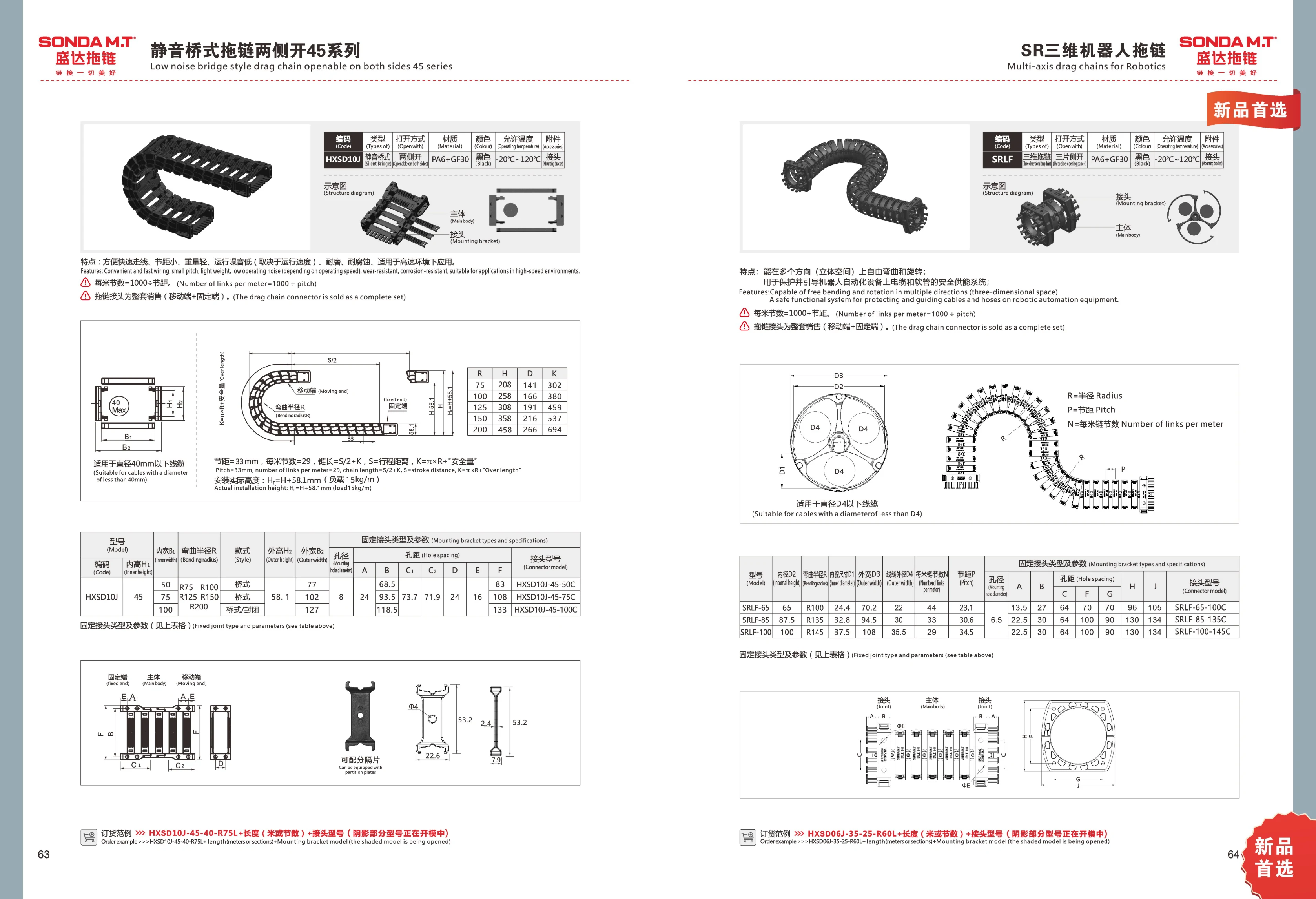
SRLF Series 3D Cable Carrier
The SRLF series is a 3D cable carrier made of black PA6+G3. It bends and rotates freely in multiple directions through three-dimensional space, protecting and guiding cables and hoses on robotic automation equipment to provide a safe energy supply system. It is available in three inner widths: 65 mm, 87.5 mm, and 100 mm, with corresponding bend radii of R100, R135, and R145. The inner cavity dimensions range from 24.4 to 37.5 mm, the outer width ranges from 70.2 to 108 mm, the number of links per meter ranges from 29 to 44, and the pitch ranges from 23.1 to 34.5 mm. Operating temperature: -20°C to 120°C. Cable carrier connectors are sold as a set (moving end + fixed end); connector models are coded according to inner width and bend radius.

MA Series Stainless Steel Mini Cylinders
MA Series stainless steel mini cylinders feature a compact, corrosion-resistant stainless steel barrel and are suitable for light-duty pushing, pulling, clamping and positioning in automated equipment. The series includes the MA standard type, MS single-acting front-spring type, MT single-acting rear-spring type and MG dual-rod adjustable-stroke type. Model numbers combine the series code, cushioning type, bore × stroke, rear cover type and mounting type. The catalog example is MA C 25×50-CA-LB. Rubber cushioning and accessories such as CA and LB are available for compact pneumatic applications in electronics, packaging, food and other industries.
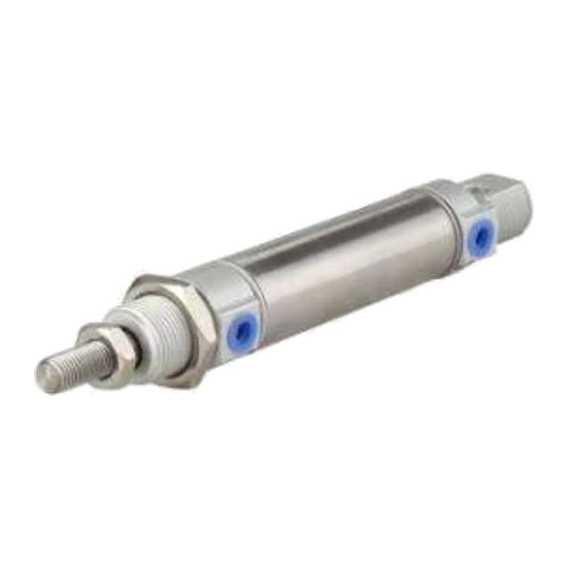
DSN Series Stainless Steel Mini Cylinders
The DSN series stainless steel mini cylinder is a FESTO-type round cylinder with a stainless steel barrel and corrosion-resistant construction. It is suitable for short-stroke linear push-pull movements, clamping, positioning, and general pneumatic actuation in automated equipment. Models are selected using code positions for the series number, bore, stroke, elastic cushioning pads, position sensing, and variants. An example from the source is DSN-32-80-P-A-MQ. The same family includes DSNU and ESNU round cylinders, while the DSW series can be custom-made. When selecting a model, confirm the bore and stroke, then specify the suffix according to cushioning, position sensing, and mounting variant requirements.

ZCUK Series Vacuum Cylinders
ZCUK series vacuum cylinders are vacuum actuators for pneumatic automation, commonly used for vacuum gripping, material handling, and positioning. The model code consists of segments indicating the series, built-in magnet or piping configuration, bore, stroke, action type, magnetic switch model, and number of magnetic switches. For example, a cylinder with a 16 mm bore and 20 mm stroke can be fitted with an M9BW magnetic switch. When selecting a model, confirm the mounting and piping configuration, action type, and number of switches. Refer to the catalog for detailed specifications.

MB Series Changtuo Square-Head Cylinder
The MB Series Changtuo square-head cylinder features a square-head body and is suitable for pushing, pressing, clamping, positioning, and reciprocating linear motion in automated equipment. According to the catalog, bore sizes of 16-25mm come standard with a magnet but without air cushioning, while bore sizes of 32-40mm come standard with both air cushioning and a magnet. When selecting a model, consider the bore size, stroke, sensor type and quantity, and whether a magnet and air cushioning are required. This series is compatible with the mounting methods used for common standard square-head cylinders.

DA Series Miniature Cylinders
The DA series miniature cylinders are identified in the catalog as corresponding to the KOGANEI series. These compact pneumatic actuators are selected by series number, whether variable cushioning and a dust boot or scraper are required, bore size, and stroke. Variable cushioning improves shock absorption at the end of the stroke, while the dust boot or scraper protects the piston rod in environments with heavy dust or cutting fluid splashes. The table repeats the bore and stroke columns, indicating that the series covers multiple bore sizes and stroke lengths. Refer to the complete catalog page or the manufacturer's selection table for available values. These cylinders are suitable for space-constrained automated fixtures and handling, positioning, and pressing mechanisms. OCR extraction of the table on this page is incomplete, and no complete, usable model codes are listed, so no model numbers have been inferred.
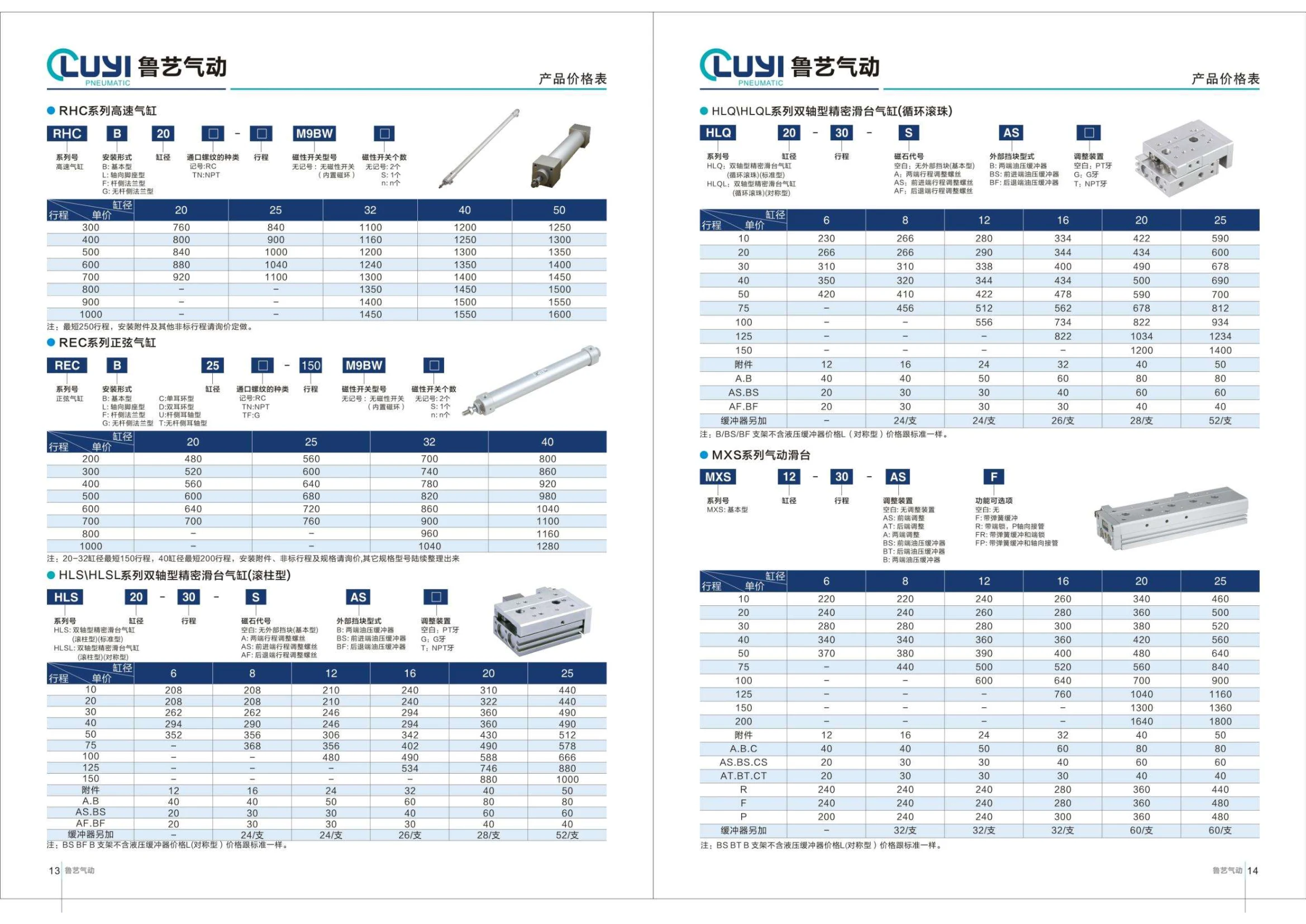
HLQ/HLQL Series Twin-Shaft Precision Slide Table Cylinders (Recirculating Ball)
The HLQ/HLQL series consists of twin-shaft precision slide table cylinders with recirculating ball guides. They are suited to automated equipment requiring high-precision linear movement, positioning, transfer, and clamping support. The series includes HLQ and HLQL models, with selection based on bore size, stroke, magnet code, external stop type, and adjustment device. External stop options include no external stop (basic type), A compression springs at both ends, and B compression spring at the front end. PT or G threads are available for adjustment/thread options. The catalog does not specify the complete bore size and stroke ranges; contact us to confirm non-standard strokes and mounting accessories.

RHC Series High-Speed Cylinders
RHC series high-speed cylinders are pneumatic actuators designed for high-speed reciprocating motion. Bore sizes include 20, 25, 32, 40, and 50 mm. Mounting styles include B basic, F rod-side flange, G non-rod-side flange, L axial expansion, D double clevis, and T types. Port threads are RC, and the standard minimum stroke is 250 mm. Magnetic switches are optional: no symbol indicates no magnetic switch, and if the number of magnetic switches is not specified, 2 are supplied. These cylinders are suitable for frequent, rapid movements in automated equipment. Mounting accessories, non-standard strokes, and other specifications are available by custom order; please request a quote.

REC Series Sine Cylinder
The REC series sine cylinder is a double-acting pneumatic actuator. The catalog uses REC as the series designation, with orders specified using a multi-part code: mounting type - bore - port thread type - stroke - magnetic switch model - number of magnetic switches. Mounting options include basic type B, rod-side flange type F, rodless-side flange type G, double clevis type D, and axial expansion type L. Common bore sizes are 25, 40, 50, 80, and 100 mm. Port threads are designated RC, with other thread types available. Magnetic switches can be fitted; the standard configuration includes 2 switches, while no designation indicates no magnetic switch. Stroke limits depend on bore size: bores of 20~32 have a minimum stroke of 150, while a 40 bore has a minimum stroke of 200. Mounting accessories, non-standard strokes, and special specifications require a custom quotation. Other specifications and models will be published as they become available.
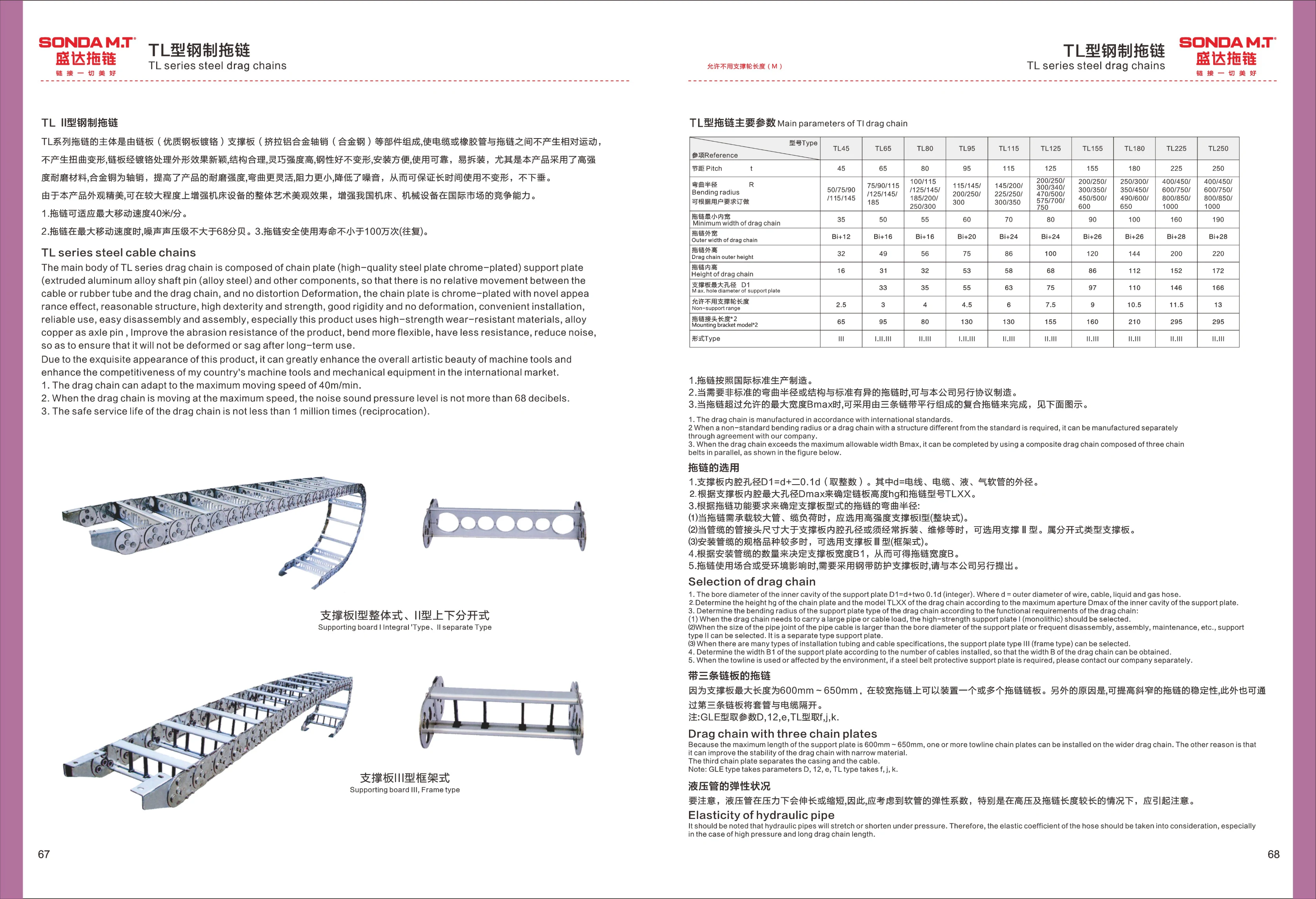
TL-Type Steel Cable Carrier
The TL Series steel cable carrier is made up of chain plates (chrome-plated high-quality steel), support plates (extruded aluminum alloy), and pins (alloy steel). This design prevents relative movement between the cables or rubber hoses and the carrier, avoiding twisting and deformation. The chrome-plated chain plates offer a distinctive appearance, a well-designed structure, high strength, and easy installation. High-strength, wear-resistant materials and alloy steel pins improve wear resistance. The carrier bends smoothly with low resistance and noise, and retains its shape without sagging even after prolonged use. It supports a maximum travel speed of 40 m/min, with a noise sound pressure level of no more than 68 dB and a safe service life of at least 1 million cycles (reciprocating). Suitable for machine tools and other applications, it enhances both appearance and competitiveness. Models include TL45, TL65, TL80, TL95, TL115, TL125, TL150, TL180, TL225, and TL250. Pitches range from 45 mm to 250 mm, with a choice of bend radii. Inner widths correspond to the model number (35 mm for TL45, 50 mm for TL65, and the same as the model number for all other models).
HLS/HLSL Series Twin-Shaft Precision Slide Cylinders (Roller Type)
The HLS/HLSL series comprises twin-shaft precision slide cylinders with twin-shaft guides and roller slides, suited to automated applications requiring high rigidity, smooth linear motion, and precise positioning. The series includes the HLS standard type and HLSL symmetrical type, with bore sizes of 20, 30, 40, 50, 80, and 100 mm. When ordering, specify the bore size, stroke, magnet code, external stop type, adjustment device, and other options. The minimum stroke is 150 mm for bore sizes 20~32 and 200 mm for bore size 40. Mounting accessories, non-standard strokes, and other specifications are custom-made; contact us for a quote.

MXQ Series Pneumatic Slide Table
The MXQ series is a pneumatic slide table (slide table cylinder) with an integrated symmetrical guide rail and table structure, designed for precision linear transfer, positioning, and clamping. The model number consists of five parts: series, bore size, type, stroke, and adjustment device. Bore sizes are 6, 8, 10, 12, 16, 20, and 25 mm, with stroke options depending on the bore size (standard range: 10~200 mm). Types include the basic type and the L symmetrical type. Adjustment options include no adjustment device, front-end adjustment AS, rear-end adjustment AT, hydraulic shock absorbers at both ends B, rear-end hydraulic shock absorber BT, front-end metal stopper C, and various combinations such as F/FR/FP/P with spring cushions and end locks. These provide end-of-stroke stopping, cushioning, and position holding during power loss. The table can be mounted on multiple sides and is suitable for linear transfer mechanisms in automated equipment for electronics, automotive parts, packaging, and other applications.

CXSJM Series Twin-Rod Cylinder
The CXSJM series twin-rod cylinder is a pneumatic actuator with two parallel piston rods that move in sync. It offers resistance to twisting, precise guidance, and high load capacity, making it suitable for clamping, lifting, anti-rotation, and precision positioning applications. Cylinders can be selected by bore size and stroke. Common bore sizes include 20mm, with strokes ranging from short to medium and long. Flexible mounting options are available, and magnetic switches can be fitted for position detection.
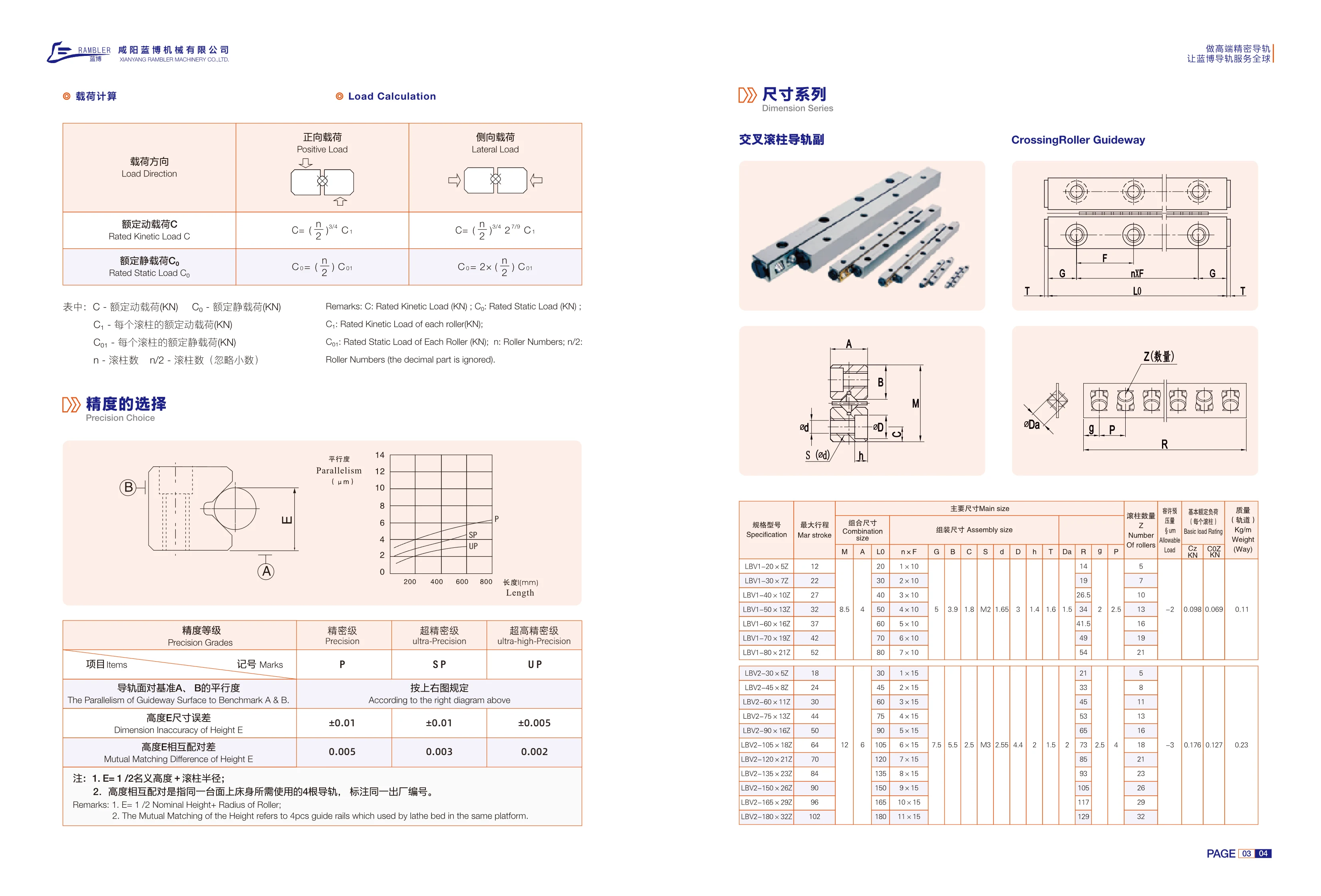
LBV Series Crossed Roller Guideway Sets
The LBV series crossed roller guideway is a linear guidance component that uses cylindrical rollers arranged at 90° to one another. It can support both vertical and lateral loads simultaneously and offers high rigidity, low friction, and high positioning accuracy. It is suitable for automated equipment requiring high-rigidity, high-precision linear motion. The series comprises two cross-sectional sizes: LBV1 (assembled width 10mm, main dimension 5mm) and LBV2 (assembled width 15mm, main dimension 5mm). Each size is available in multiple assembled lengths (20~80mm for LBV1 and 30~180mm for LBV2), with a corresponding number of rollers (5Z~32Z) and maximum strokes of 12~102mm. Select a model based on parameters including maximum stroke, assembled dimensions, roller count, allowable load, and basic load rating.
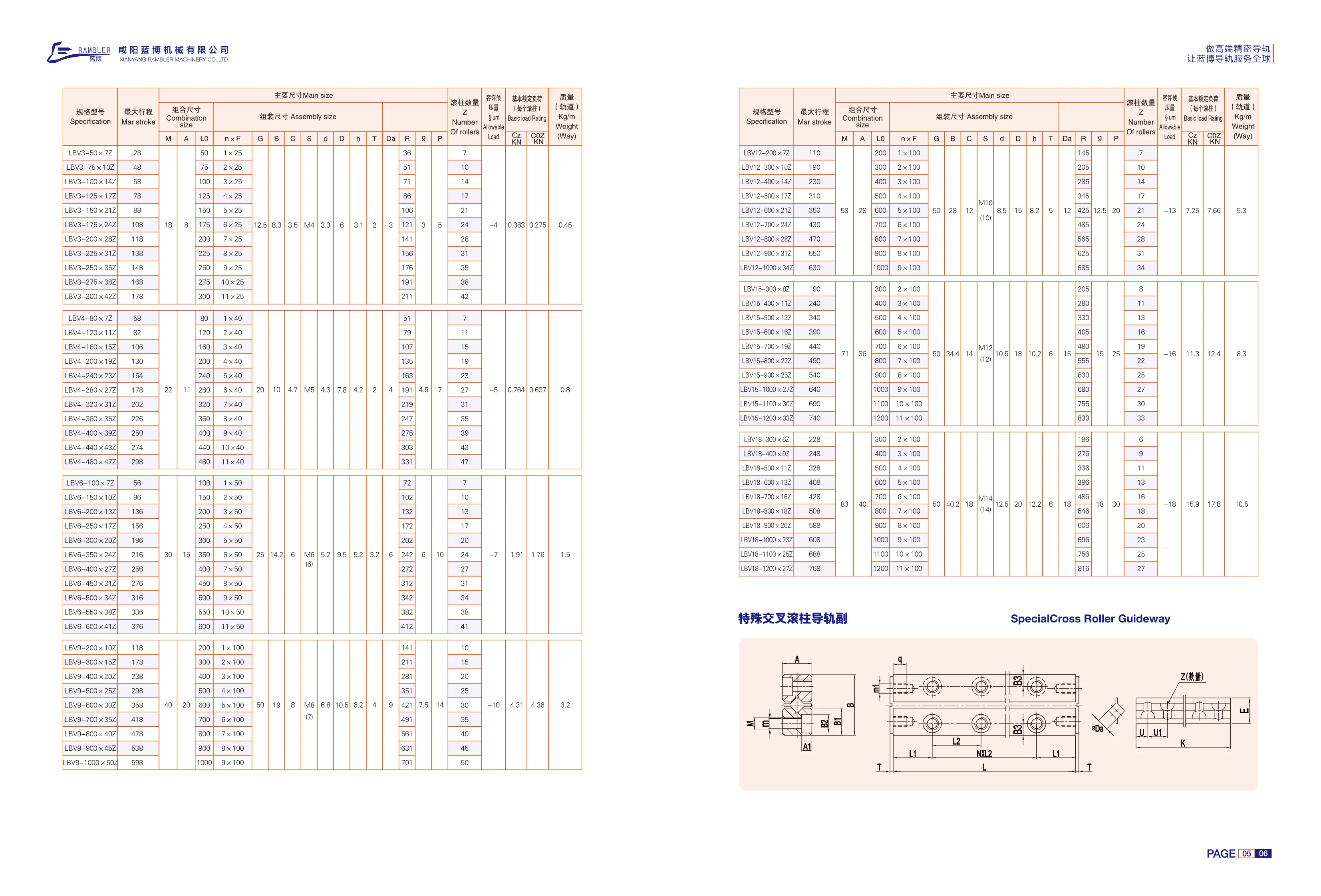
LBV Series Roller Linear Guides
LBV series linear guides use cylindrical rollers as rolling elements. Compared with ball-type guides, the rollers make line contact with the raceways, providing a larger contact area and therefore greater rigidity, higher load capacity, and better impact resistance. They are suitable for heavy-duty cutting, machine tool feed axes, heavy-load handling, and automation equipment. The catalog lists three cross-sectional size codes: 12, 15, and 18. Rail lengths range from 200~1000 mm for size 12 and 300~1200 mm for sizes 15 and 18, in 100 mm increments. Standard mounting holes are arranged at an n×100 pitch, with the number of holes increasing from 1 to 11 as the rail length increases. The catalog specifies the maximum travel for each length: 110~630 mm for size 12, 190~740 mm for size 15, and 228~768 mm for size 18. The model designation follows the format “LBV size-rail length×suffix code.” Suffix codes are specified for each size and length combination; for example, size 12 with a 200 mm rail corresponds to 72, and a 300 mm rail corresponds to 102. When selecting a model, it is necessary to
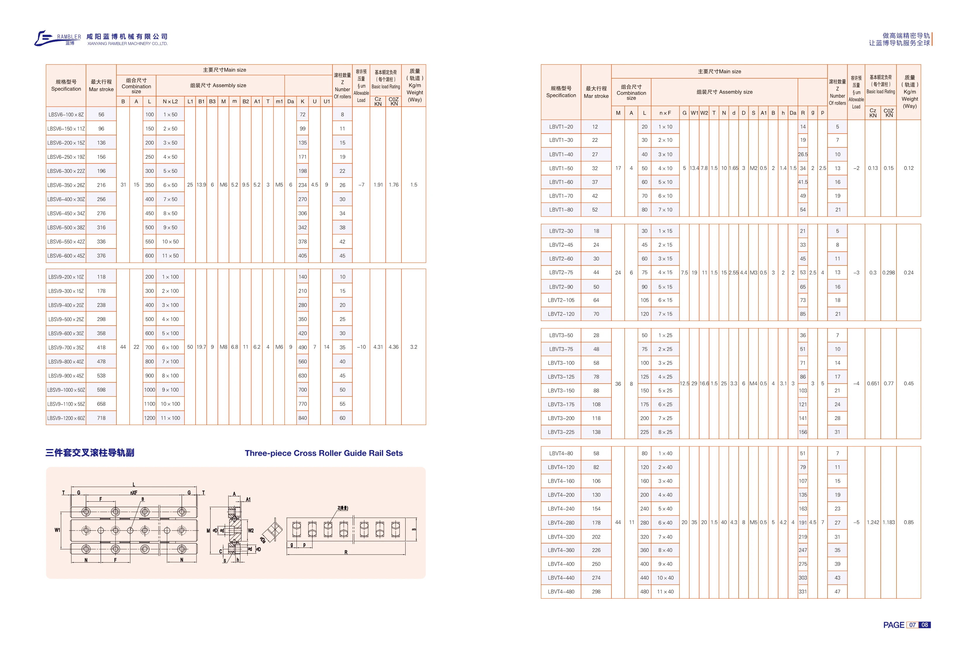
LBVT Series Roller Linear Guides
LBVT series roller linear guides use cylindrical rollers as rolling elements. Compared with ball-type linear guides of the same size, they offer a larger contact area, higher load ratings and rigidity, and better resistance to shock and vibration. They are suited to linear motion applications requiring high rigidity and repeat positioning accuracy, such as machine tools, precision measuring instruments, and automated assembly lines. The series comes in four cross-sectional sizes: 1, 2, 3, and 4. Standard rail lengths range from 20~480mm, with corresponding maximum strokes of 12~298mm. Within each size, rail lengths increase in increments of the fixed hole pitch (10mm for size 1, 15mm for size 2, 25mm for size 3, and 40mm for size 4), with the number of mounting holes increasing from 1 to 11. Models are designated LBVT[size]-[rail length] and can be selected based on stroke requirements. Slider preload grades and lubrication accessories can also be specified as needed.
LBSV Series Roller Linear Guides
The LBSV series consists of roller linear guides that use cylindrical rollers as rolling elements. They offer high rigidity, high load capacity, and low friction, making them suitable for heavy-duty linear guidance in machine tools, automated equipment, and similar applications. The LBSV6-100×82 model listed in the catalog has a maximum stroke of 56 mm. Its main dimensions include B=31 mm, A=15 mm, L=100 mm, L1=25 mm, B1=13.9 mm, and B3=6 mm. See the corresponding table for the number of rollers and rated load values.
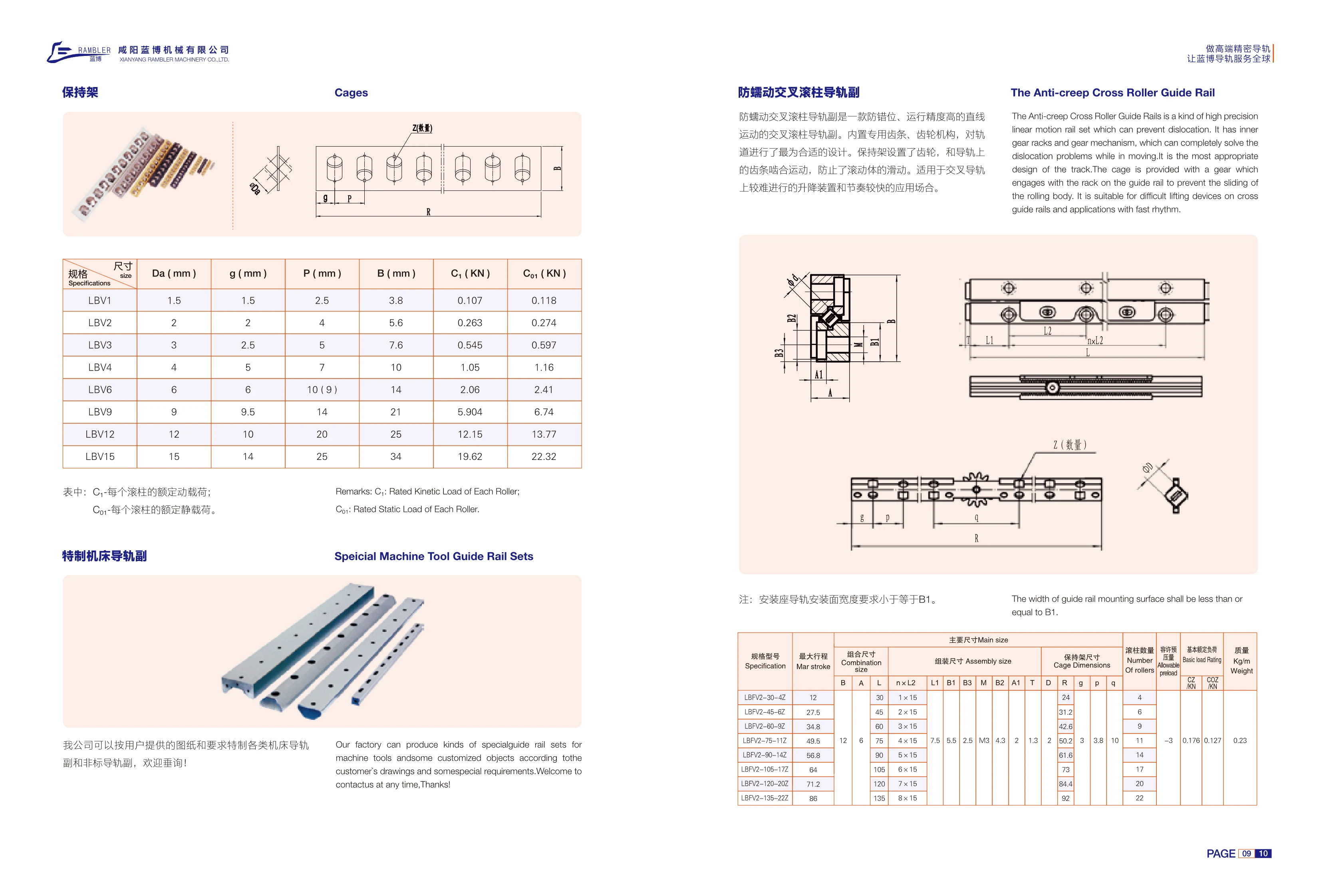
LBV Series Anti-Creep Crossed Roller Guide Set
The LBV series anti-creep crossed roller guide set provides precise linear motion while preventing misalignment. Its built-in rack-and-pinion mechanism features a gear on the cage that engages with a rack on the guide rail. This completely prevents rolling element slip (creep), addressing the challenge of preventing misalignment in lifting devices and high-cycle applications. The width of the guide rail mounting surface on the mounting base must be no greater than B1. The series includes 8 sizes, from LBV1 to LBV15, covering roller diameters Da of 1.5~15mm and guide rail widths B of 3.8~34mm. Basic dynamic load ratings C1 range from 0.107kN to 19.62kN, and static load ratings C01 range from 0.118kN to 22.32kN. These guide sets are suitable for high-precision linear guidance and rapid lifting applications where misalignment must be prevented.
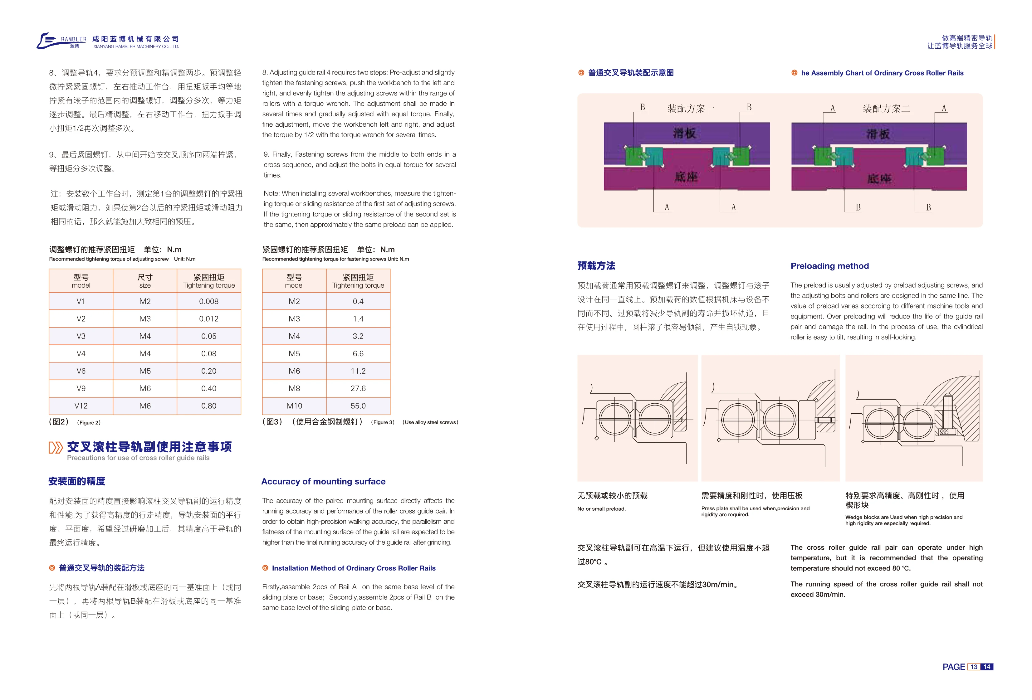
V Series Crossed Roller Guideways
V Series crossed roller guideways are high-precision linear motion guide components. They use cylindrical rollers arranged in a crossed pattern to support loads from multiple directions, making them suitable for machine tools, precision measuring equipment, and automation systems. During installation, the mating mounting surfaces must have flatness and parallelism tolerances tighter than the guideway's final running accuracy; grinding is usually required. Preload is adjusted using preload adjustment screws aligned with the rollers. Adjustment must be performed in two stages, preliminary and fine, with repeated tightening in a crisscross sequence at equal torque. Excessive preload can shorten guideway life, damage the tracks, and cause cylindrical rollers to tilt and lock. The catalog lists adjustment screw sizes and recommended tightening torques for V1, V2, V3, V4, V6, V9, and V12 models, ranging from M2~M6 and 0.008~0.80 N·m, respectively, for reference when setting preload during installation.

M/V Type Needle Roller Guideway Set
The M/V type needle roller guideway set uses a needle roller cage and is suitable for high-load, high-rigidity linear guidance applications. Compared with similar needle roller systems, the LB type composite needle roller cage reduces motion resistance while maintaining high rigidity. The catalog lists six sizes: 3015, 4020, 5025, 6035, 7040, and 8050, with width A of 30~80 mm, height B of 15~50 mm, and needle roller diameter Dw of 2~3.5 mm. Standard lengths can be selected from the length table for each size, with maximum lengths of 1200~1500 mm. Other dimensions are available on request.
N/O and M/V Needle Roller Guideway Sets
N/O and M/V needle roller guideway sets are precision crossed needle roller guideways designed with needle roller cages for high-load applications. The M/V type uses an LB composite needle roller cage that provides low motion resistance and high rigidity compared with similar needle roller systems. The N/O type also uses a needle roller cage, with closely spaced rollers that give the guideway high rigidity. M/V sizes include 3015, 4020, 5025, 6035, 7040 and 8050, with cross-sectional dimensions A=30~80 mm and B=15~50 mm, needle roller diameter Dw=2~3.5 mm, and selectable lengths of 100~1500 mm. N/O dimensions are not listed on this page; please contact us for details.
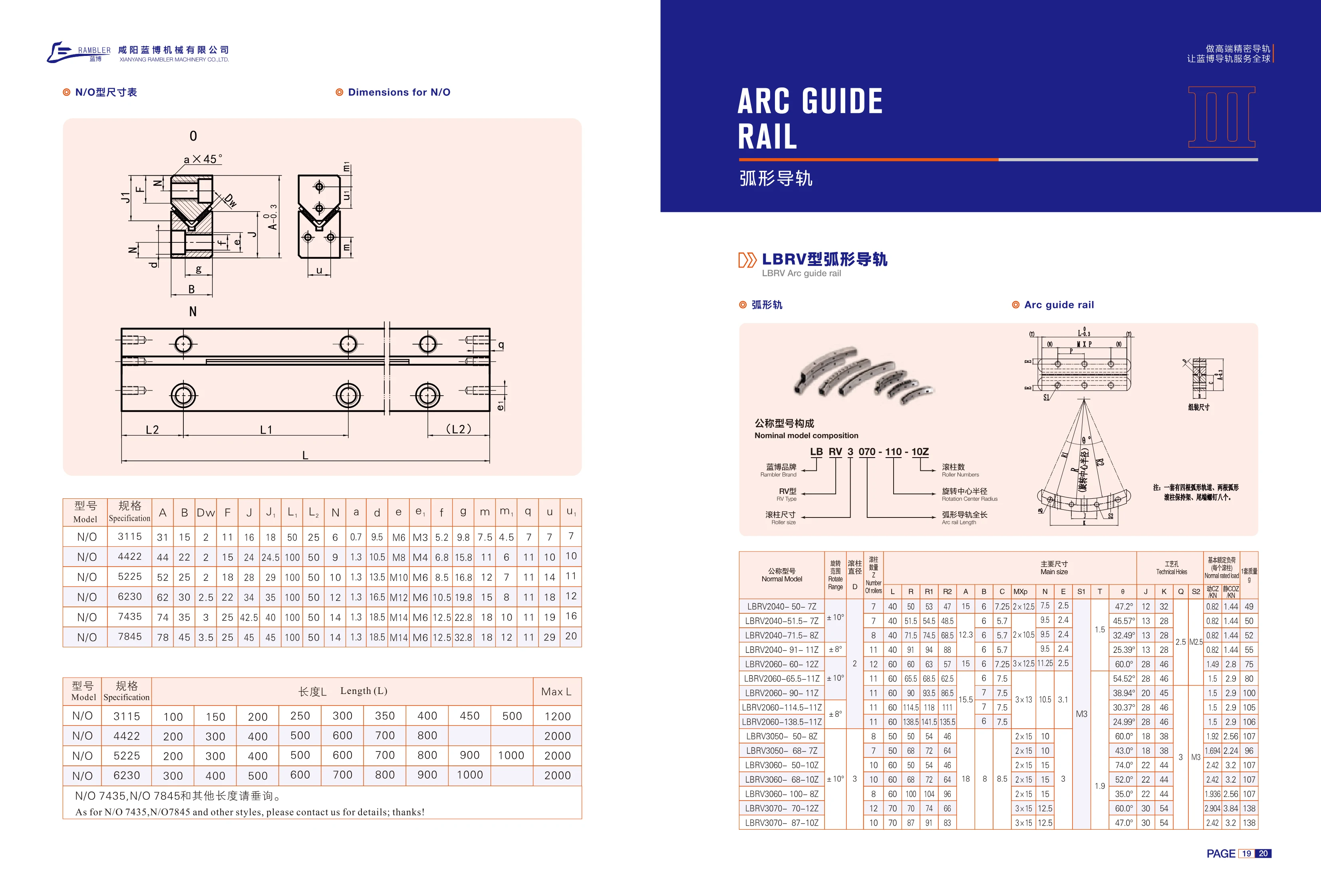
N/O Type Linear Guide Rails
The N/O type linear guide rail (rolling guide rail) series uses model numbers consisting of N/O and a four-digit size code, such as N/O 3115 and N/O 4422. The size code corresponds to the cross-sectional dimensions. The dimension table provides cross-sectional and mounting parameters including A, B, Dw, F, J, J1, L1, L2, N, a, d, e/e1, f, g, m/m1, q and u/u1, where Dw is the ball diameter and e/e1 specifies the threaded holes. Standard lengths vary by size: 3115 is 100~500mm (in 50mm increments, maximum 1200mm); 4422 is 200~800mm (in 100mm increments, maximum 2000mm); 5225 is 200~1000mm (maximum 2000mm); and 6230, 7435 and 7845 are 300~1000mm (maximum 2000mm). Please inquire about 7435, 7845 and other lengths.
LBRV Curved Guide Rail
LBRV curved guide rails provide guidance along an arc and are commonly used in curved workstations, rotary mechanisms, and curved conveying systems in automated equipment. The catalog lists the N/O series in sizes 3115–7845, with cross-sectional widths A of 31–78 mm, heights B of 15–45 mm, roller diameters Dw of 2–3.5 mm, and mounting threads from M6 to M14. Length L can be selected from standard increments, typically 100–1000 mm, with maximum lengths of 1200–2000 mm. Consult us for 7435, 7845, and other lengths.
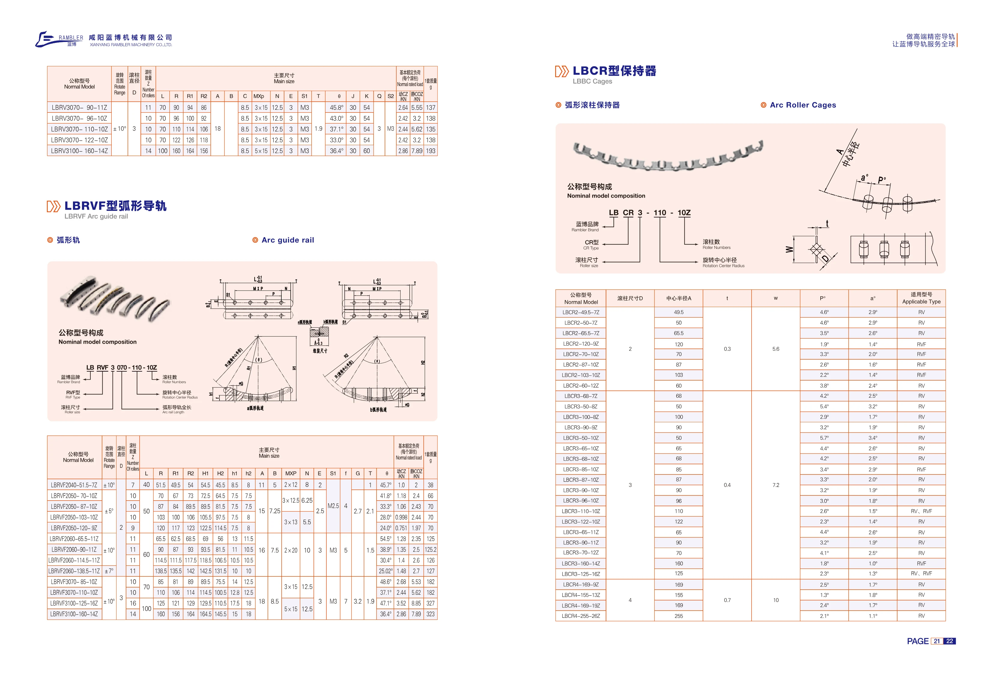
LBCR Series Crossed Roller Bearing Roller Assemblies
The LBCR series consists of roller assemblies for crossed roller bearings (RV and RVF types). Cylindrical rollers and a cage are supplied as a set and installed between the inner and outer ring raceways to retain the rolling elements. The series is divided into D2, D3 and D4 sizes by roller diameter D, with corresponding structural dimensions t of 0.3, 0.4 and 0.7, and w of 5.6, 7.2 and 10, respectively. Center radius A ranges from 49.5~255 mm. The roller count is indicated by a suffix from 7Z to 26Z (7~26 rollers). P° and a° are angular parameters describing the circumferential arrangement of the rollers. They vary with center radius and roller count, ranging from approximately 1.3°~5.7°. The catalog also provides the basic load rating per roller for load calculations. Select the assembly according to the mating bearing's center radius A, required roller count and applicable model (RV or RVF). The same nominal model may have multiple sets of angular parameters; final fit depends on the mating bearing's raceway dimensions.
RV Series Curved Guide Rails
RV series curved guide rails provide guidance along an arc and are commonly used with LBCR series roller cages. The series comes in three roller diameters: 2, 3 and 4 mm. Center radii range from 49.5 to 255 mm, and the cages contain 7 to 26 rollers. The P and a angular parameters are used to match the cages to RV and RVF guide rails. The multi-roller cage design offers low friction, high rigidity, accurate positioning and smooth motion. Applications include rotary tables, curved conveyors, inspection equipment and curved slide tables in automated machinery. Select the appropriate LBCR nominal model based on the guide rail model, center radius and roller size.
LBCR Series Rollers
LBCR series rollers are cylindrical rollers designed specifically for RV and RVF series cycloidal pinwheel reducers. They are available in three diameters—2mm, 3mm and 4mm—with center radii ranging from 49.5mm to 255mm and roller counts of 7, 8, 9, 10, 11, 12, 13, 14, 16, 19 or 26. Each model specifies the P° and a° angle parameters and the compatible reducer type (RV or RVF). As essential rolling elements in a reducer, the rollers' precision and material directly affect transmission efficiency and service life. Made from high-quality bearing steel and precision-machined and heat-treated, these rollers offer high hardness, excellent wear resistance and a long service life. They are suitable for manufacturing and repairing RV/RVF reducers used in industrial robots, machine tools, packaging machinery and other applications.
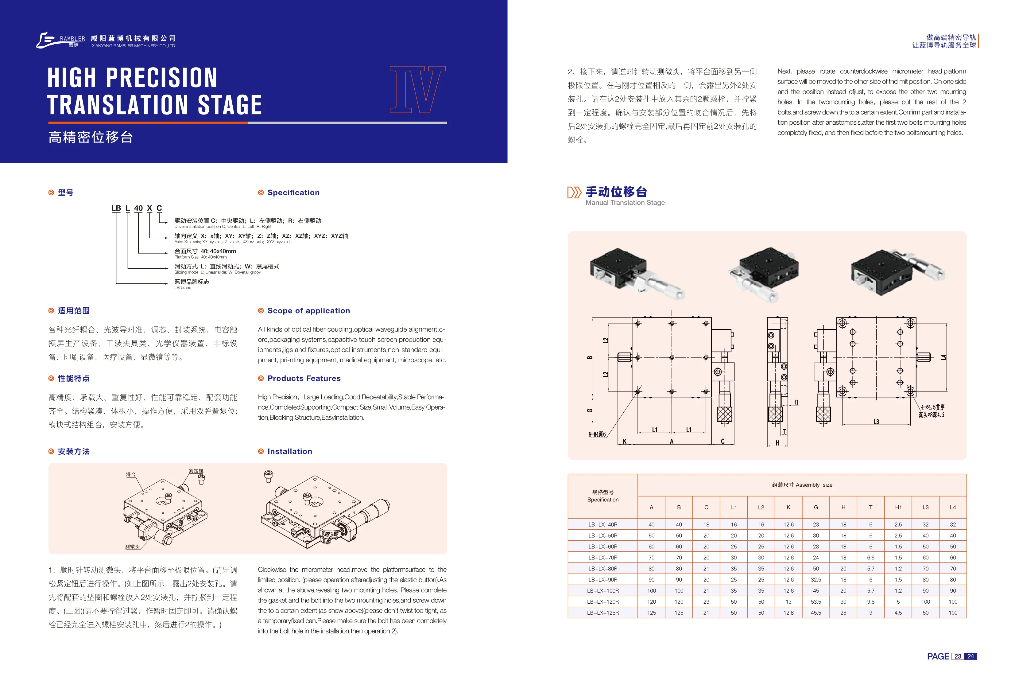
LB-LX Series High-Precision Manual Translation Stages
LB-LX series high-precision manual translation stages use linear sliding guides and are available with platform sizes from 40×40mm to 125×125mm. They support single-axis X, Y or Z motion and combined two-axis XZ or YZ motion. The drive can be mounted in the center (C), on the left (L), or on the right (R). Driven by a micrometer head and equipped with a dual-spring return, these stages offer high precision, high load capacity, good repeatability, reliable and stable performance, a compact size, and easy operation. Their modular construction makes installation easy and offers a full range of compatible functions. Applications include fiber-optic coupling, optical waveguide alignment, core alignment, packaging systems, capacitive touchscreen production equipment, jigs and fixtures, optical instruments, custom equipment, printing equipment, medical equipment, and microscopes. Select the model according to platform size and drive position, and refer to assembly dimensions A/B/C, L1~L4, and K/G/H/T/H1 when planning the installation.
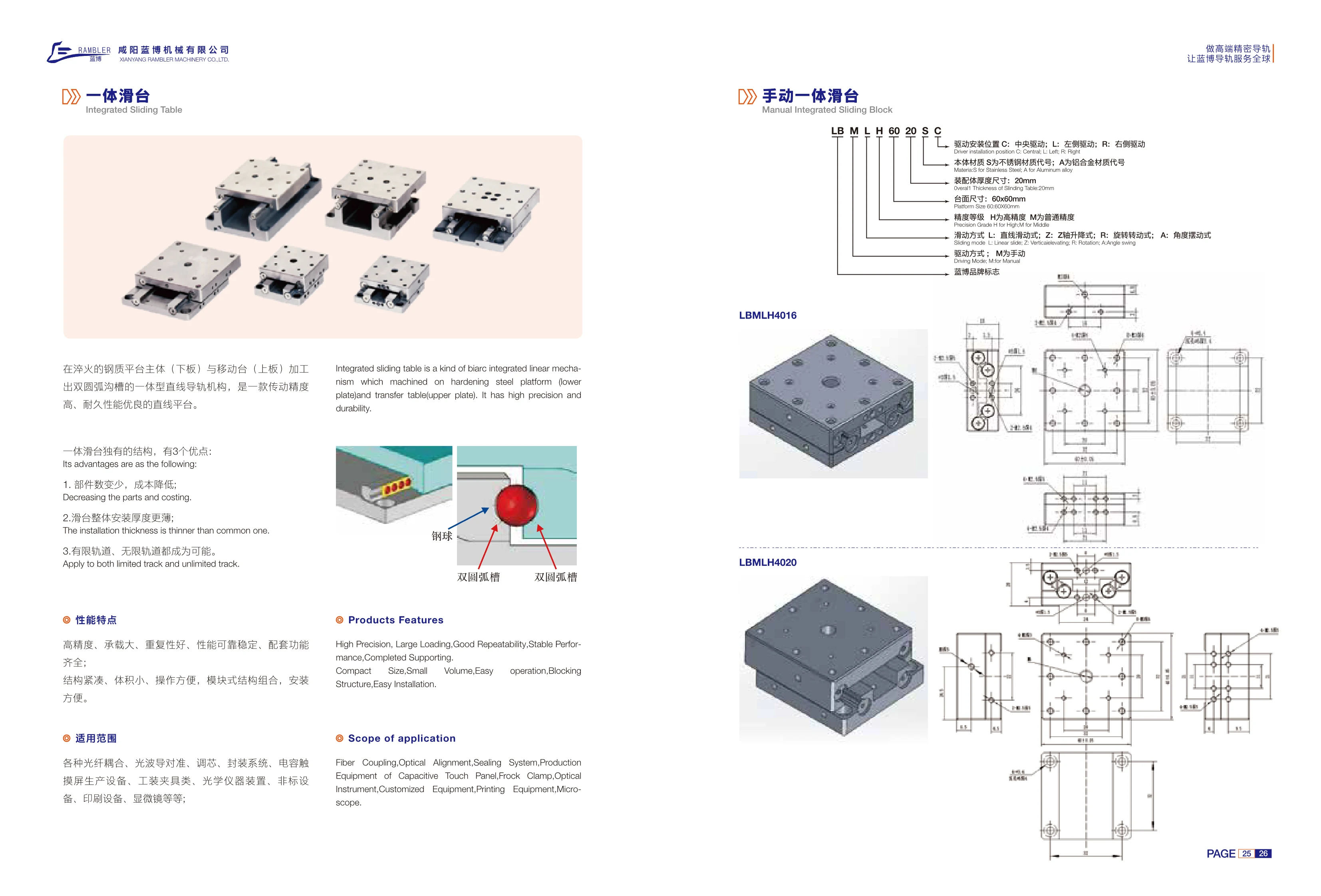
LBMH Series Manual Integrated Slide Stages
The LBMH series manual integrated slide stage is a linear guide mechanism with double-arc grooves machined directly into the hardened steel platform body (lower plate) and moving table (upper plate). Balls circulate in the double-arc grooves between the two plates, providing high motion accuracy and excellent durability. Compared with conventional modular slide stages consisting of a rail, carriage, and table, the integrated design offers three advantages: fewer components and lower cost; a thinner overall assembly; and support for both limited-travel and unlimited-travel rails. The table measures 60×60mm, and the assembly is in the 20mm thickness class. The body is available in stainless steel or aluminum alloy (code A). Selection options include drive mounting position (C center, L left, R right), accuracy grade (H high accuracy, M standard accuracy), motion type (L linear sliding, Z Z-axis lifting, R rotation, A angular oscillation), and drive type (M manual). Applications include manual fine adjustment, inspection fixtures, optical alignment, and positioning in compact automation equipment.
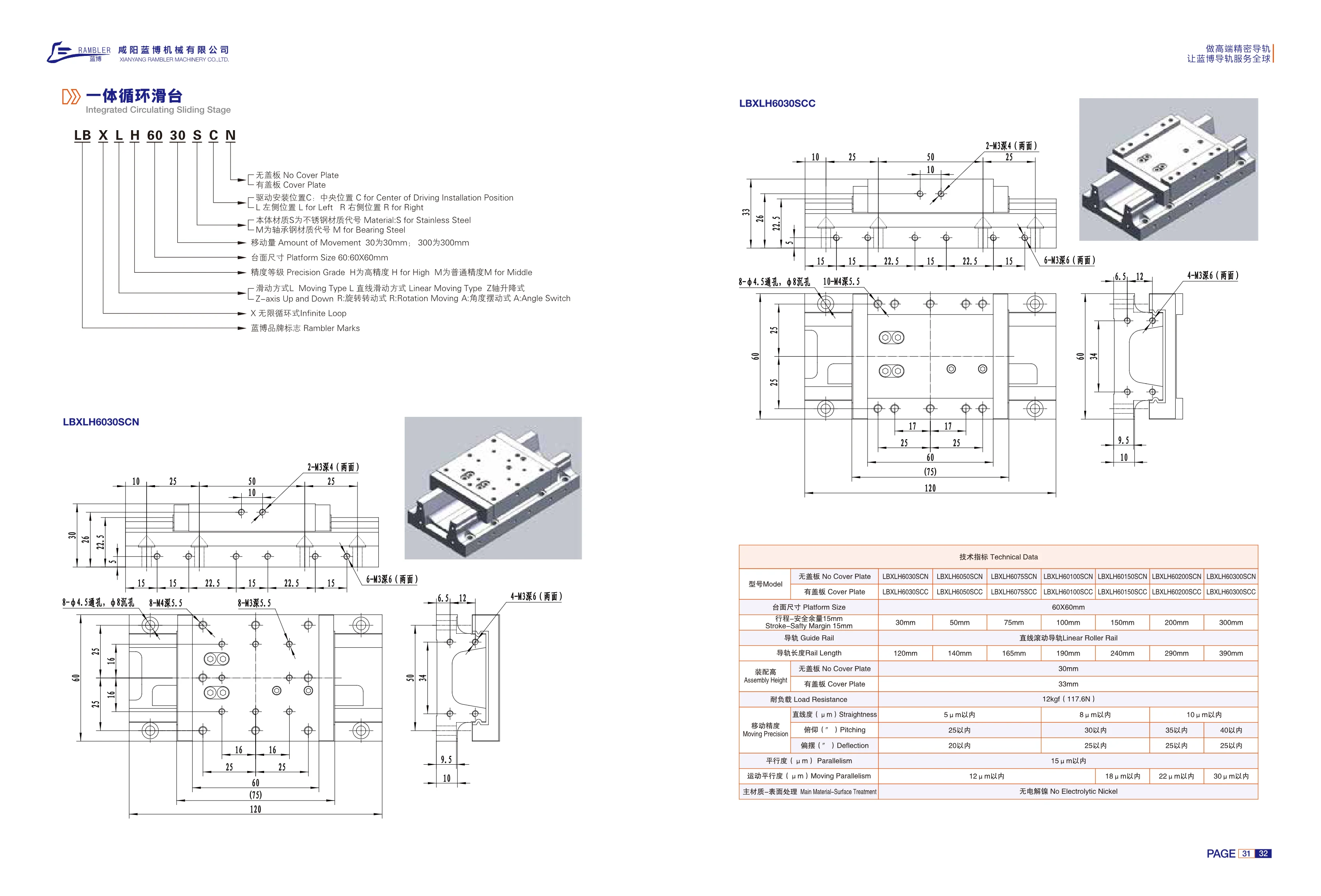
LBXLH Series Integrated Recirculating Slide
The LBXLH series integrated recirculating slide is a passive infinite-loop linear motion stage with a linear rolling guide. It has a 60×60mm platform, a travel range of 30~300mm with a 15mm safety margin, and corresponding guide rail lengths of 120~390mm. It is available with or without a cover plate, with assembly heights of approximately 33mm and 30mm respectively. Body material options are stainless steel (S) and bearing steel (M). Drive mounting positions are center (C), upper left (L), and right (R). Accuracy grades are high (H) and standard (M). Motion types include linear sliding (L), axial lifting (Z), rotary motion (R), and angular oscillation (A). The load capacity is approximately 12kgf (117.6N), straightness is within 5~10μm, and parallelism is within 15μm. The surface is electroless nickel plated. The slide is suitable for automation applications in electronics, inspection, precision assembly, and related fields.
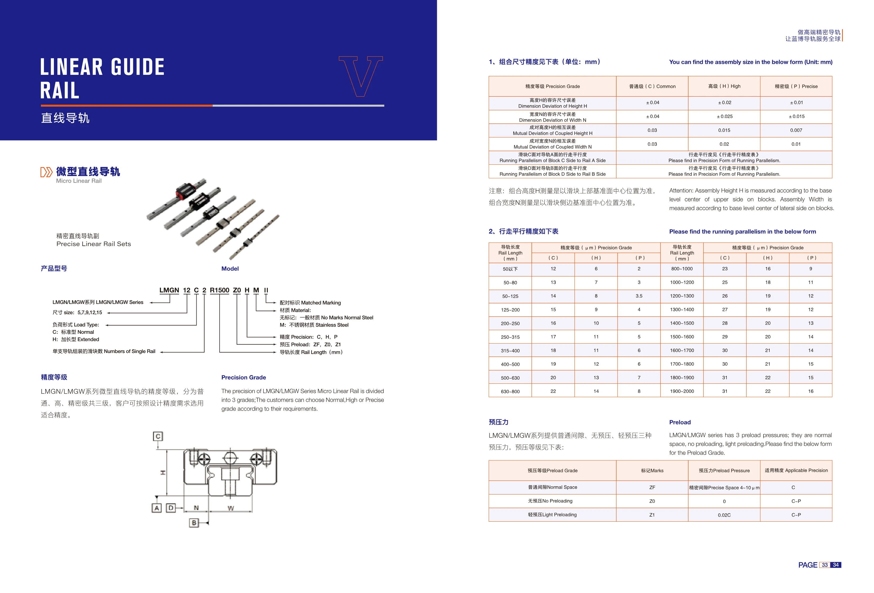
LMGN/LMGW Series Miniature Linear Guides
The LMGN/LMGW series consists of miniature precision linear guide assemblies comprising a miniature rail and carriage. They are suitable for light-load, high-precision linear guidance in compact automation equipment, semiconductor and medical equipment, inspection instruments, and similar applications. Rails are available in five sizes: 5, 7, 9, 12, and 15. Two load types are offered: C standard and H extended. Each rail can accommodate 1 or more carriages. There are three accuracy grades: normal (C), high (H), and precision (P). The respective height H tolerances are ±0.04, ±0.02, and ±0.01mm, and the width W tolerances are ±0.04, ±0.025, and ±0.015mm. The allowable height variation between paired assemblies is 0.03, 0.015, and 0.007mm, and the allowable width variation is 0.03, 0.02, and 0.01mm, respectively. For the running parallelism of carriage face C relative to rail face A and carriage face D relative to rail face B, refer to the Running Parallelism Accuracy Table for the applicable rail length. Select the appropriate size, load type, and accuracy grade based on the required design accuracy and available installation space.
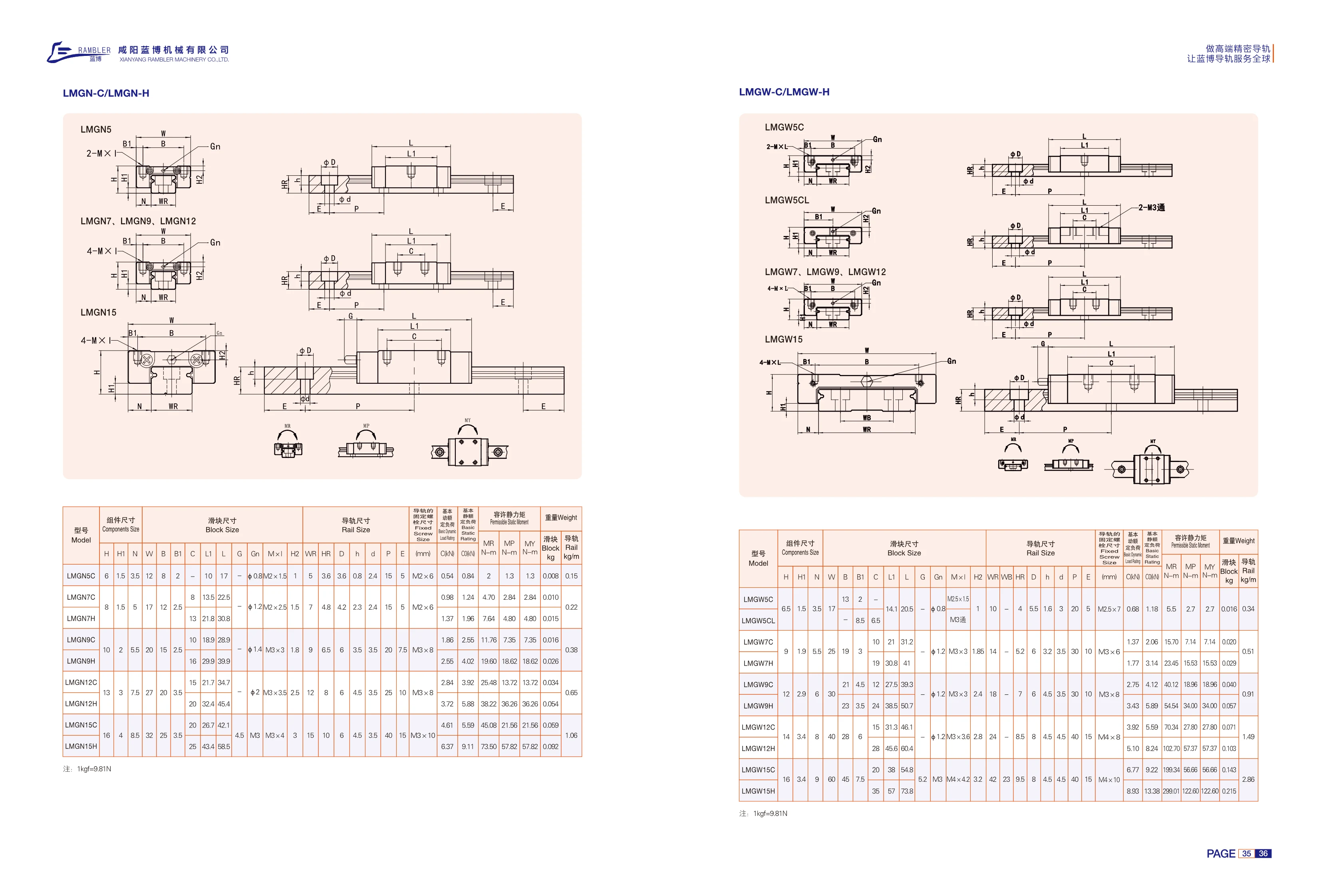
LMGW-C/LMGW-H Series Linear Guides
LMGW-C/LMGW-H miniature linear guide assemblies consist of a rail and a carriage. They use four rows of steel balls and Gothic-arch grooves with four-point contact, allowing them to withstand loads in all four directions—up, down, left and right—and provide a degree of moment resistance. The C and H types are two carriage styles and load ratings within the same series. They differ primarily in carriage length, mounting hole spacing, load ratings and permissible static moments. The compact C type has a short overall length and is suited to space-constrained applications with light to medium loads. The H type has an extended carriage, more rows of steel balls and longer effective travel, as well as higher dynamic and static load ratings and permissible static moments. It is suited to applications with longer overhangs or impact loads. The catalog specifies assembly dimensions (assembly width, mounting height and carriage mounting hole spacing), carriage dimensions (width, length, height and mounting hole thread), rail dimensions (width, height, mounting hole spacing and number of holes), rail mounting dimensions, basic dynamic and static load ratings, permissible static moments in the MA/MB/MC directions, and carriage and rail weight per meter. Select the size and carriage type based on load, moment and available mounting space, then determine the rail length and number of holes based on travel requirements.
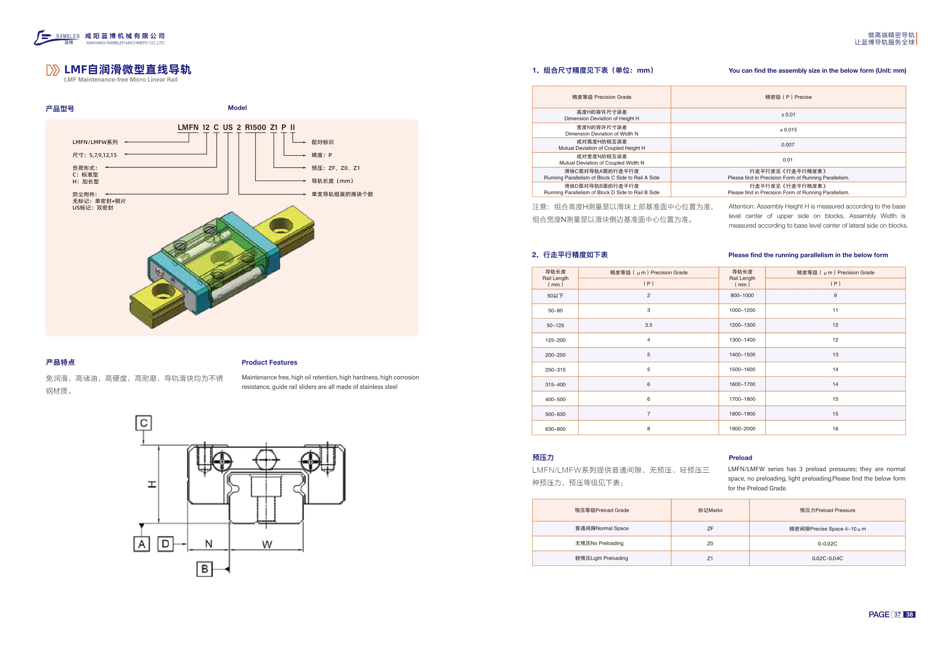
LMF Series Self-Lubricating Miniature Linear Guideways
The LMF series of self-lubricating miniature linear guideways includes two configurations, LMFN and LMFW, in five cross-sectional sizes: 5, 7, 9, 12, and 15. Blocks are available in C standard and H long load types. Dust protection options include a single seal + steel plate (no designation) or double seals (US designation). Both rails and blocks are made of stainless steel and feature lubrication-free operation, high oil retention, high hardness, wear resistance, and corrosion resistance. They are suitable for compact, low-maintenance linear guidance applications. The accuracy grade is P precision grade, with a tolerance of ±0.01 mm for assembly height H and ±0.015 mm for assembly width N. Running parallelism varies with rail length; the catalog provides a segmented accuracy table for lengths from under 50 mm to 2000 mm. Model example: LMFN 12 C US 2 R1500 Z1 P II.
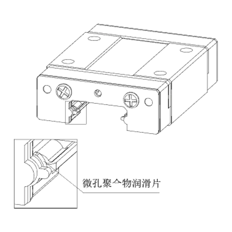
LMFN/LMFW Series Miniature Linear Guides
The LMFN/LMFW series comprises miniature linear guides: LMFN features standard blocks, while LMFW features wide blocks. They are suitable for applications requiring a low profile, light weight and high rigidity, including compact automation equipment, precision instruments, semiconductor equipment and medical devices. The catalog covers sizes 5, 7, 9, 12 and 15, with C (standard) and H (extended/high-load) block types. Dimension tables list assembly dimensions, block and rail mounting holes, basic load ratings, permissible static moments and weights, making it easy to select a model based on available space, load and moment requirements. The wider LMFW design provides greater resistance to lateral moments.
LMFN/LMFW Series Miniature Linear Guides
The LMFN/LMFW series of miniature linear guides comes in narrow (LMFN) and wide (LMFW) configurations. Model numbers consist of the series designation, size (5, 7, 9, 12, 15), and block type (C standard / H extended). Their miniature cross-section makes them suitable for space-constrained applications such as precision instruments, compact automation equipment, and semiconductor equipment. The catalog provides parameters for selection and installation, including assembly height H, block width W, block length L, rail width, rail height, mounting hole pitch, basic dynamic/static load ratings, allowable static moments (MR/MP/MY), and block and rail weights.
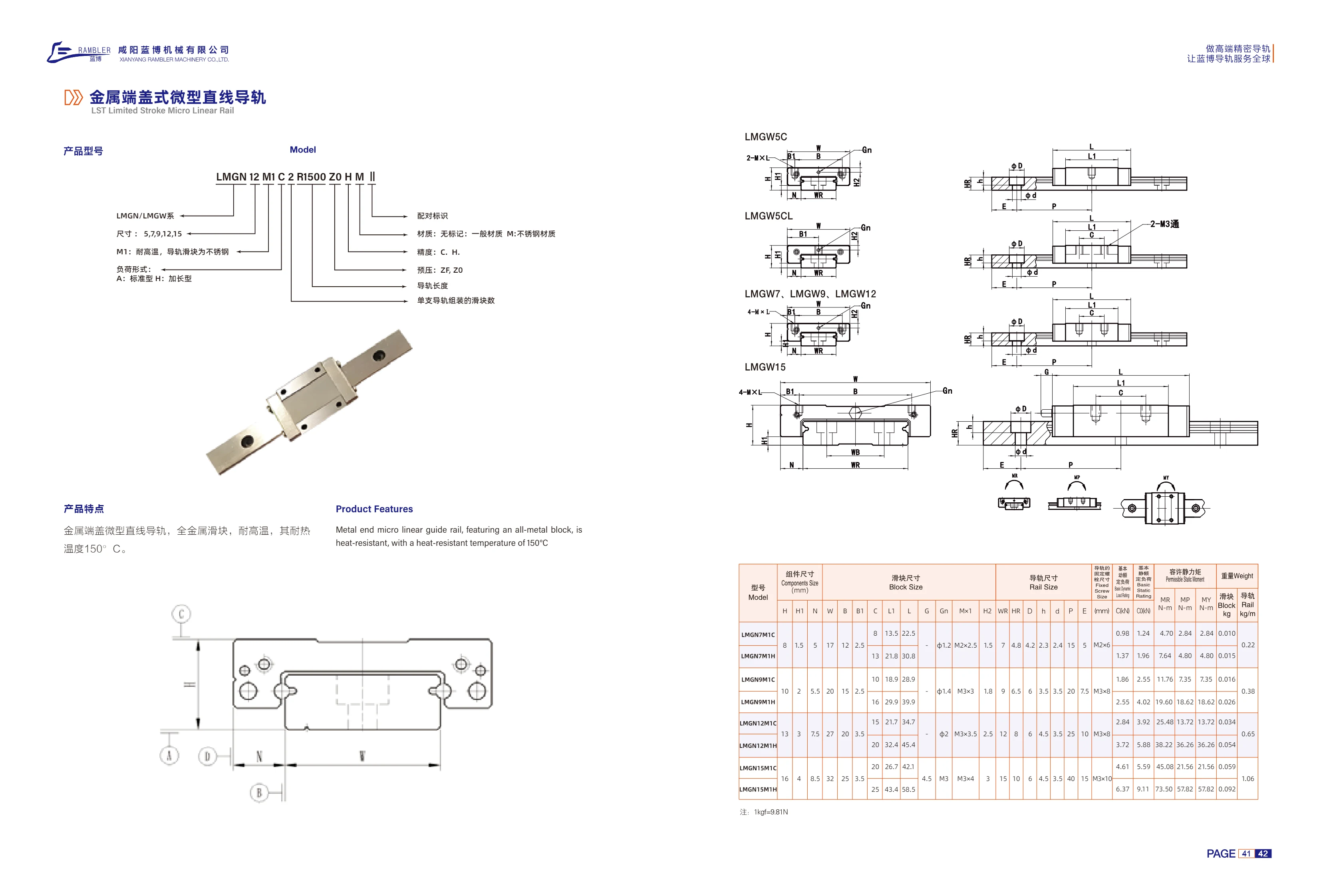
LMGN/LMGW Series Metal End Cap Miniature Linear Guides
The metal end cap miniature linear guide (LST Limited Stroke Micro Linear Rail) features an all-metal carriage and metal end caps. It withstands temperatures up to 150°C and provides precision linear guidance in harsh conditions, including high temperatures and dusty environments. The series includes LMGN and LMGW models in sizes 5, 7, 9, 12, and 15. Material options include standard material or unmarked M stainless steel. M1 is the high-temperature type, with both the rail and carriage made of stainless steel. Carriage types are A standard and H extended. Accuracy grades are C and H, and preload grades are ZF and ZO. Rail length and the number of carriages assembled on each rail can be specified as required.

LST Series Limited-Stroke Miniature Linear Guide
The LST series limited-stroke miniature linear guide features miniature blocks and a short-stroke design for precision linear guidance in confined spaces in electronic equipment, semiconductor equipment, precision instruments, and medical devices. Available sizes include 7A, 9A, 12A, and 15A, with configurations selectable by RH rail height and R rail length. Common lengths range from 36~174 mm. Accuracy grades include standard grade H, with an allowable dimensional tolerance of ±0.02 mm for height H and a paired height variation of 0.03 mm. The full ordering code can also specify preload Z1, accuracy grade C, and material M (stainless steel). Codes in parentheses in the model list, such as F8D and F12D1, are specification codes from the original text.
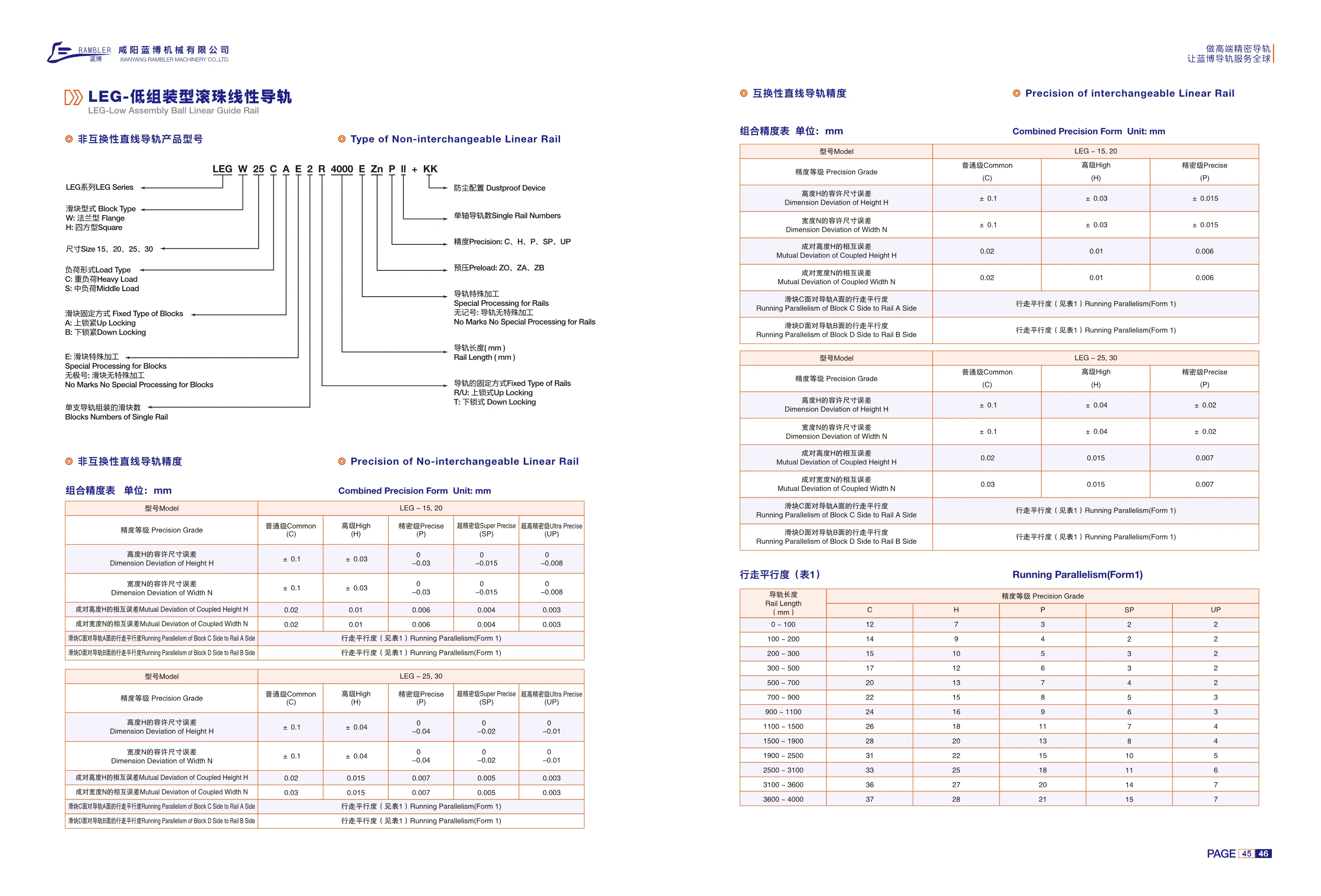
LEG Series Non-Interchangeable Linear Guides
The LEG series consists of non-interchangeable linear guides. The blocks and rails are machined and matched as sets, providing high assembly accuracy; if damaged, the entire set must be replaced. Blocks are available in flanged (W) and square (H) types, in four sizes: 15, 20, 25 and 30. Load types are heavy load (C) and medium load (S). Block mounting options are top mounting (A) and bottom mounting (B). Special block machining is also available (E; no code indicates no special machining). Accuracy grades are normal (C), high (H), precision (P), super precision (SP) and ultra precision (UP). Assembly accuracy is controlled by the permissible dimensional errors in height H and width N, as well as the differences in height and width between matched blocks. Running parallelism of block surfaces C/D relative to rail surfaces A/B is also specified in ranges according to rail length (0~4000 mm). Multiple blocks can be assembled on a single rail. Model numbers follow the sequence: block type-size-load type-mounting method-special block machining-number of blocks-rail type-rail length-special rail machining-surface treatment-accuracy grade-dust protection accessories.
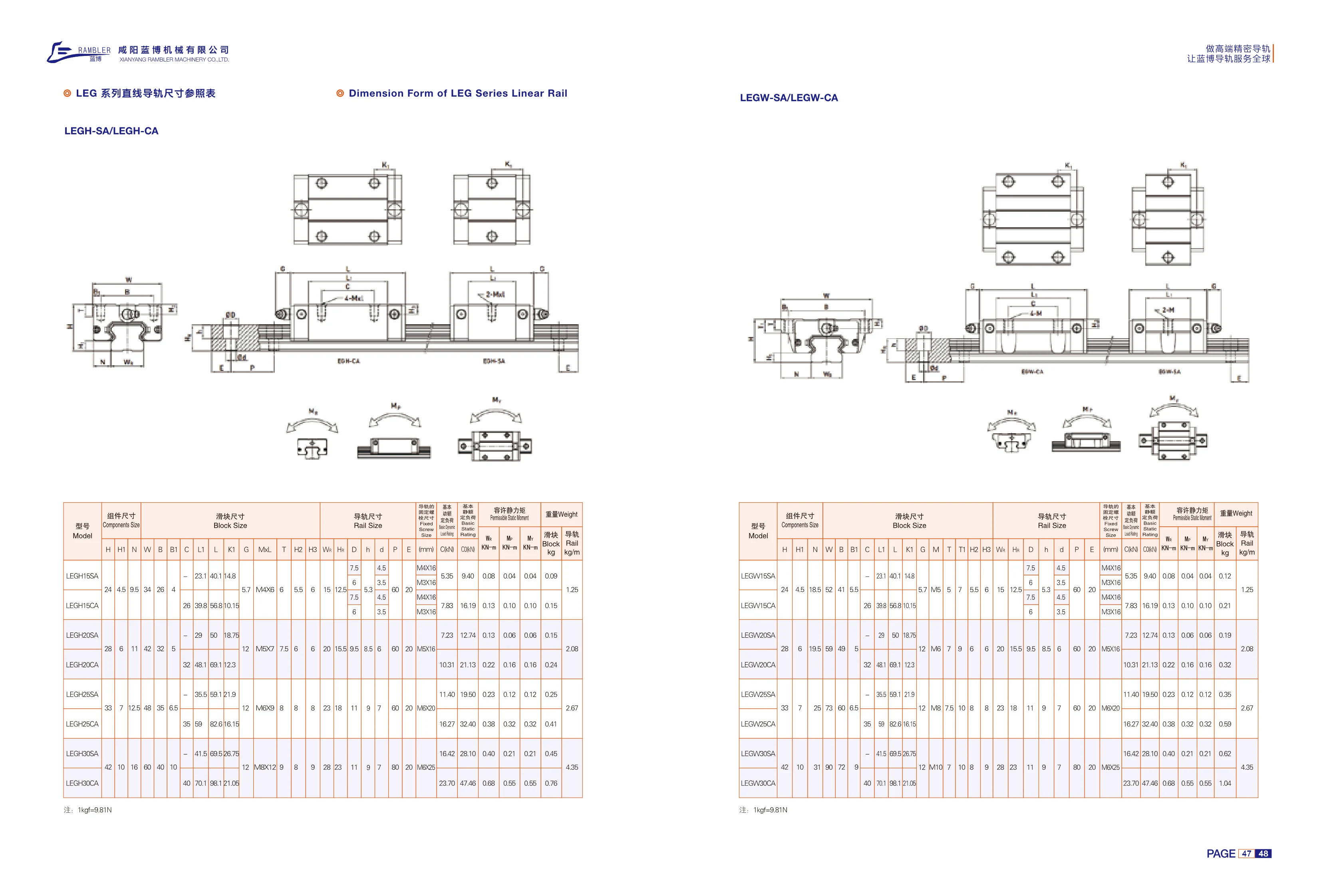
LEG Series Linear Guides
The LEG series of linear guides includes LEGH-SA, LEGH-CA, LEGW-SA, and LEGW-CA configurations for linear guidance and load support in automation equipment. The catalog provides selection parameters including assembly dimensions, block dimensions, rail dimensions, mounting bolt sizes, basic static friction coefficient (as stated in the source), allowable static moment, and weight. LEGH and LEGW denote different rail and block cross-section series, while SA and CA indicate different block mounting styles. Select the specific model from the dimensional reference table based on the available installation space, load direction, and moment conditions.
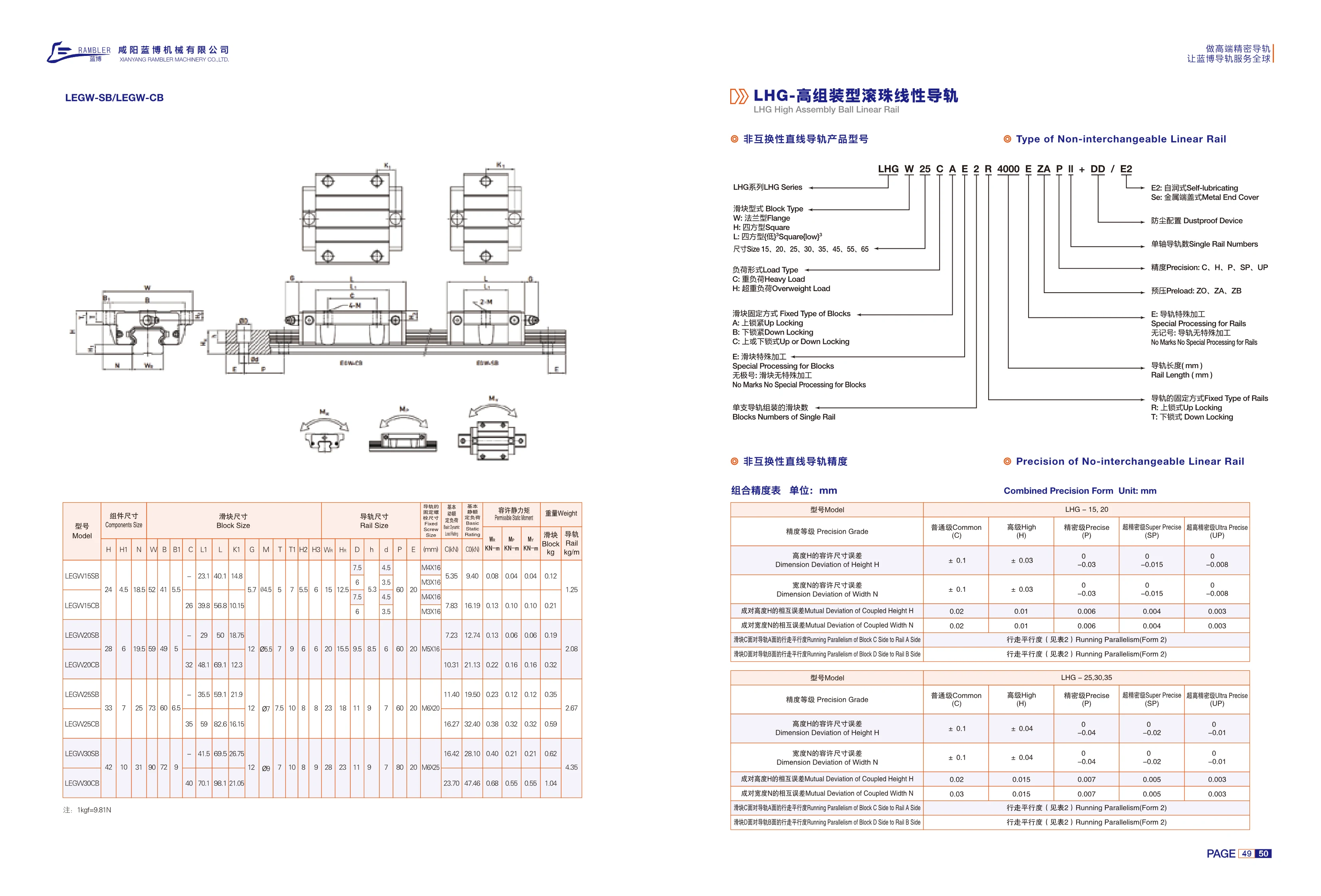
LHG Series Linear Guides
The LHG series comprises non-interchangeable linear guides with block and rail assemblies. Common configurations include LHGHA-CA and LHGHA. Products are available in five accuracy grades: normal C, high H, precision P, super precision SP, and ultra precision UP. Each grade specifies tolerances for height H and width N, variations in height and width between paired assemblies, and the running parallelism of the block relative to the rail. The dimension tables cover assembly, block, and rail dimensions, including H, H1, N, W, B, B1, C, L, L1, K, G, MxL, T, H2, H3, W, Hr, D, h, d, P, and E. These guides are suitable for automated equipment, precision machine tools, and linear motion mechanisms.
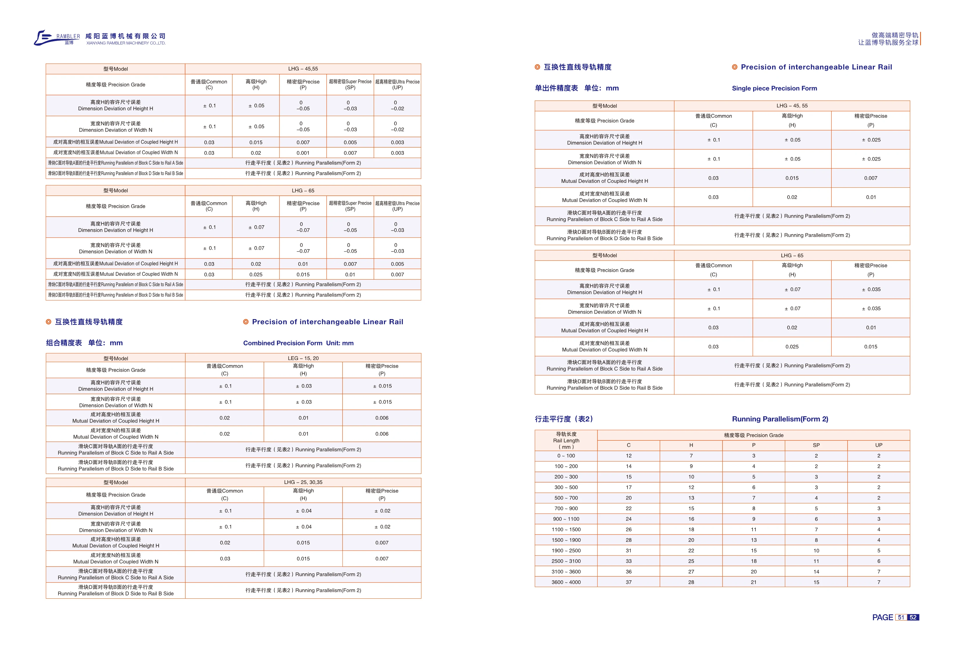
LHG Series Interchangeable Linear Guides
LHG series interchangeable linear guides feature freely interchangeable rails and blocks for easy maintenance, replacement and inventory management. Six cross-sectional sizes are available: 25, 30, 35, 45, 55 and 65. There are five accuracy grades: normal C, high H, precision P, ultra-precision SP and ultra-precision UP. Individual component accuracy is controlled by the dimensional tolerances for height H and width N: both are ±0.1 mm for normal grade, ±0.04~±0.07 mm for high grade, and 0 for precision grade and above. When used in pairs, allowable variation is reduced according to grade: paired height variation decreases from 0.02~0.03 mm to 0.005 mm, and paired width variation decreases from 0.03 mm to 0.005~0.007 mm. Running parallelism between block surface C and rail surface A, and between block surface D and rail surface B, is specified in Table 2 by rail length from 0~4000 mm. Longer rails have higher allowable values, while higher accuracy grades have lower allowable values. These guides are suitable for machine tools, automation equipment, semiconductor equipment and other applications requiring accurate travel and easy maintenance through interchangeability.
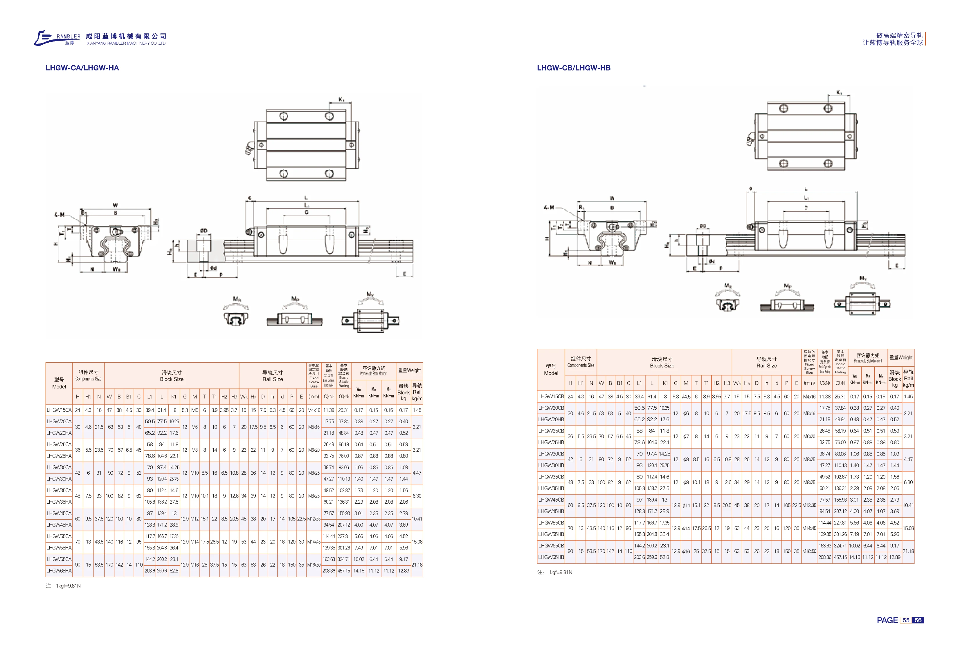
LHGW-CA/LHGW-HA Series Linear Guides
The LHGW-CA/LHGW-HA series consists of four-row ball linear guides with a low-profile assembly. Blocks are available in two configurations: CA (standard) and HA (extended, high-load capacity), in nominal sizes 15/20/25/30/35/45/50/55/60. The guides use four rows of steel balls with a 45° contact angle, allowing them to withstand radial, reverse radial and lateral loads simultaneously. They offer high rigidity, low friction and smooth, easy movement. The blocks and rails are interchangeable and provide linear guidance for machine tools, automated machinery, semiconductor equipment and medical devices. The catalog lists assembly dimensions (H, H1, N, V, B, B1, C, L1, L, K1, etc.), rail dimensions (Wn, Hn, D, h, d, P, E, etc.), mounting bolt sizes, basic static friction coefficient, allowable static moments and weight. Select a model according to load, travel, installation space and accuracy grade.

TL Series Steel Cable Carrier
The TL Series steel cable carrier is a mechanical component designed to protect cables and pipes. It is suitable for industrial applications such as machine tools and automation equipment. The series includes two models, TL115 and TL125, with pitches of 115 mm and 125 mm, respectively. The carrier is available in three designs: one-piece (Type I), top-and-bottom split (Type II), and frame-style (Type III). It supports several connection methods: standard, Type A, and Type B. The support plates can be drilled as needed to make it easier to route cables inside the carrier. The overall carrier length is calculated by multiplying the number of links by the pitch. Made of steel, it offers high strength and wear resistance, making it suitable for high-load and high-speed applications.

SYX-S Series Linear Guide Rails
The SYX-S series comprises high-performance linear guide block assemblies designed for high-precision linear motion in automation equipment. It includes several subtypes—standard (BN), extended (BL), compact (BS), flange (FS), and standard flange (FN)—to accommodate different installation spaces and load requirements. The range covers 10 sizes, from 515 to 555, with block widths of 24–70 mm, dynamic load ratings of 11.38–114.44 kN, and static load ratings of 16.97–148.33 kN. The rails are made of high-carbon steel and precision-ground, while the blocks contain rolling steel balls for low friction, high rigidity, and long service life. The products offer full dimensional interchangeability, with mounting-hole spacing and reference surfaces strictly standardized.

TLG Steel Drag Chain
TLG steel drag chains can carry large quantities of cables and oil hoses. They can run unsupported without support wheels. The bend radius ranges from 75 to 600 mm, chain plate height from 50 to 150 mm, maximum travel is 32 m, support plate width ranges from 50 to 600 mm, and the pitch is 5 mm. They are suitable for machine tools, mobile machinery, and other applications. Two configurations are available: TLGA (top and bottom sections separate) and TLGB (with removable separators). Support plates can be made to order, and bend radii from 50 to 600 mm are available. Connection hole positions follow the KRS standard.