Pneumatic Components — Page 28
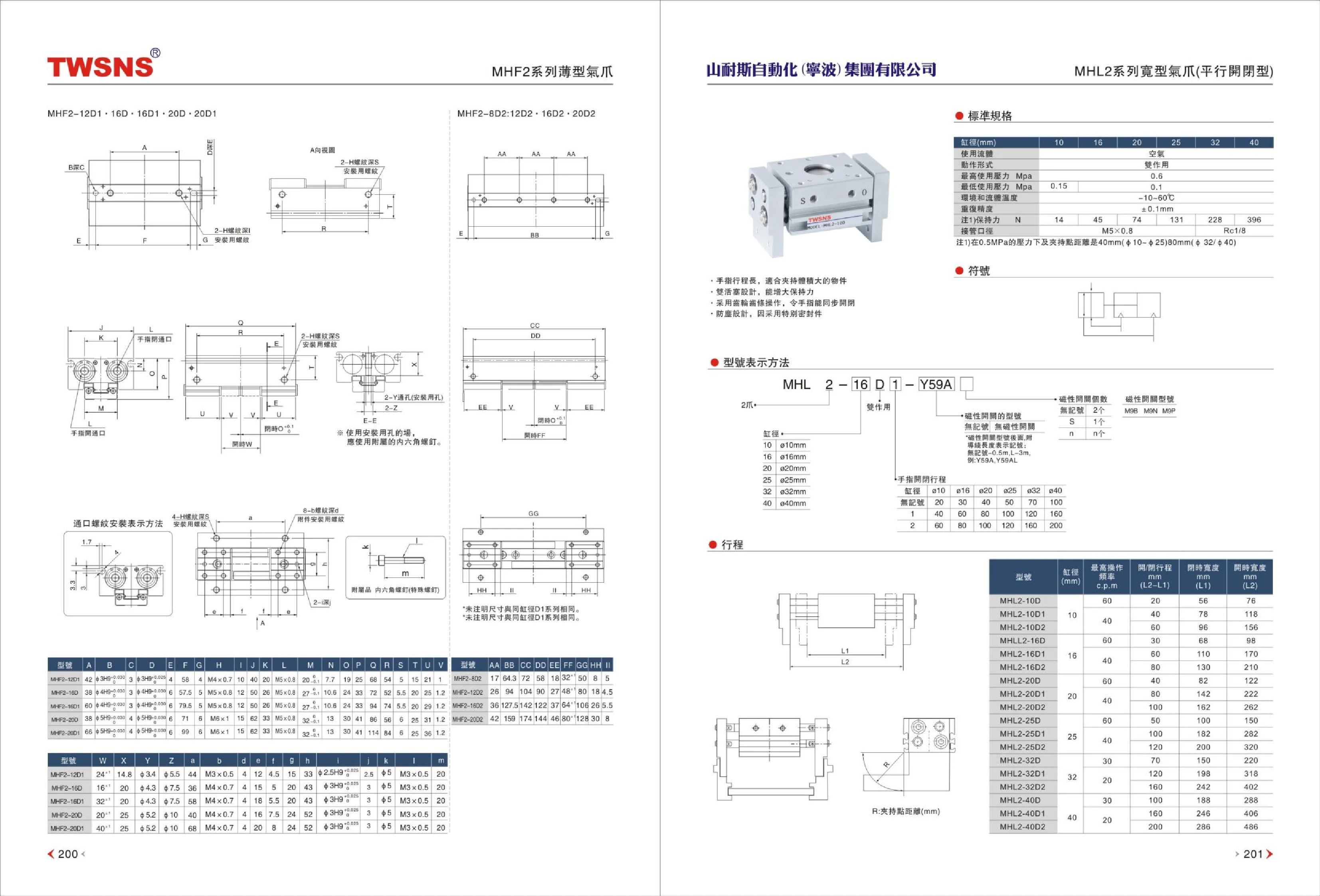
MHF2 Series Pneumatic Grippers
MHF2 series pneumatic grippers (parallel grippers) are used to grip, position, and transfer workpieces in automated equipment. Models such as MHF2-8D2, MHF2-12D1, MHF2-16D2, and MHF2-20D1 denote different bore sizes and design variants. Common bore sizes are 8, 12, 16, and 20 mm, with variants identified by codes such as D, D1, and D2. The catalog also provides a standard specifications table and port thread installation notation. The operating pressure is in the 0.15 MPa range. These grippers are suitable for small pneumatic fixtures, assembly lines, inspection stations, and similar applications.

MHF2 Series Compact Pneumatic Gripper
The MHF2 Series compact pneumatic gripper is an actuator with a parallel-opening and -closing design, intended for gripping and handling workpieces in confined spaces. Its compact construction, reliable operation, and easy installation make it suitable for a wide range of equipment, including automated assembly, packaging, and inspection systems. Typically used with a pneumatic system, the gripper enables fast pickup and release. As the catalog does not provide specific technical data, consult the manufacturer’s detailed specifications for information such as bore size, stroke, and gripping force.
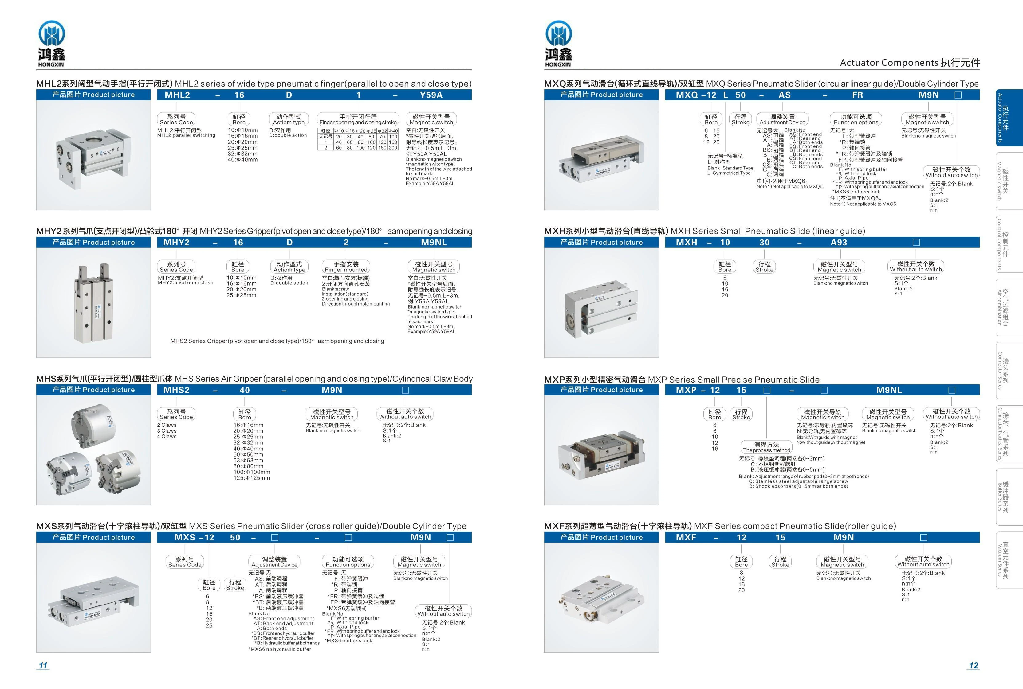
MHL2 Series Round Pneumatic Gripper
The MHL2 series round pneumatic gripper (parallel opening and closing type) is a wide pneumatic gripper designed for picking and placing workpieces. The example code on the catalog page contains the segments MHL2, size 16, type D, 1, and Y59A, which can be used to identify the bore or size, construction type, magnetic switch, and other configurations. Common specifications for this series include bore or size, opening and closing stroke, operating mode, port connection, and magnetic switch model. Refer to the complete catalog page for specific stroke, gripping force, operating pressure, and other values. This page provides only the series title and one example code; it does not include the full specification table.
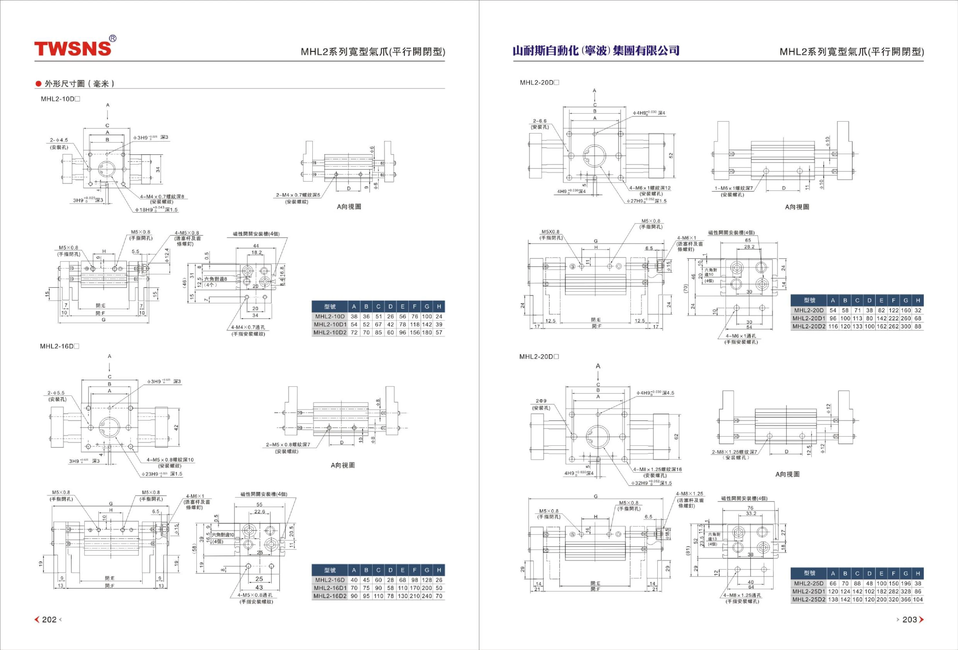
MHL2 Series Pneumatic Parallel Grippers
The MHL2 series consists of pneumatic parallel grippers with two fingers driven by a common air chamber to open and close in sync, enabling parallel gripping, handling, and positioning of workpieces. The body has mounting holes and locating surfaces for direct attachment to a cylinder, slide table, or robot arm end, while side grooves accommodate magnetic switches to detect the fully open and closed positions. The catalog distinguishes models by bore size and provides dimensional drawings in millimeters for the MHL2-10D and MHL2-20D, with A~H denoting key overall and mounting dimensions such as body width, thickness, finger stroke, and mounting hole spacing. Bore size determines body size and gripping force. Select the bore based on workpiece weight, gripping point overhang, and required gripping force, and use a pressure regulator to control gripping force and prevent damage to thin-walled or fragile workpieces.
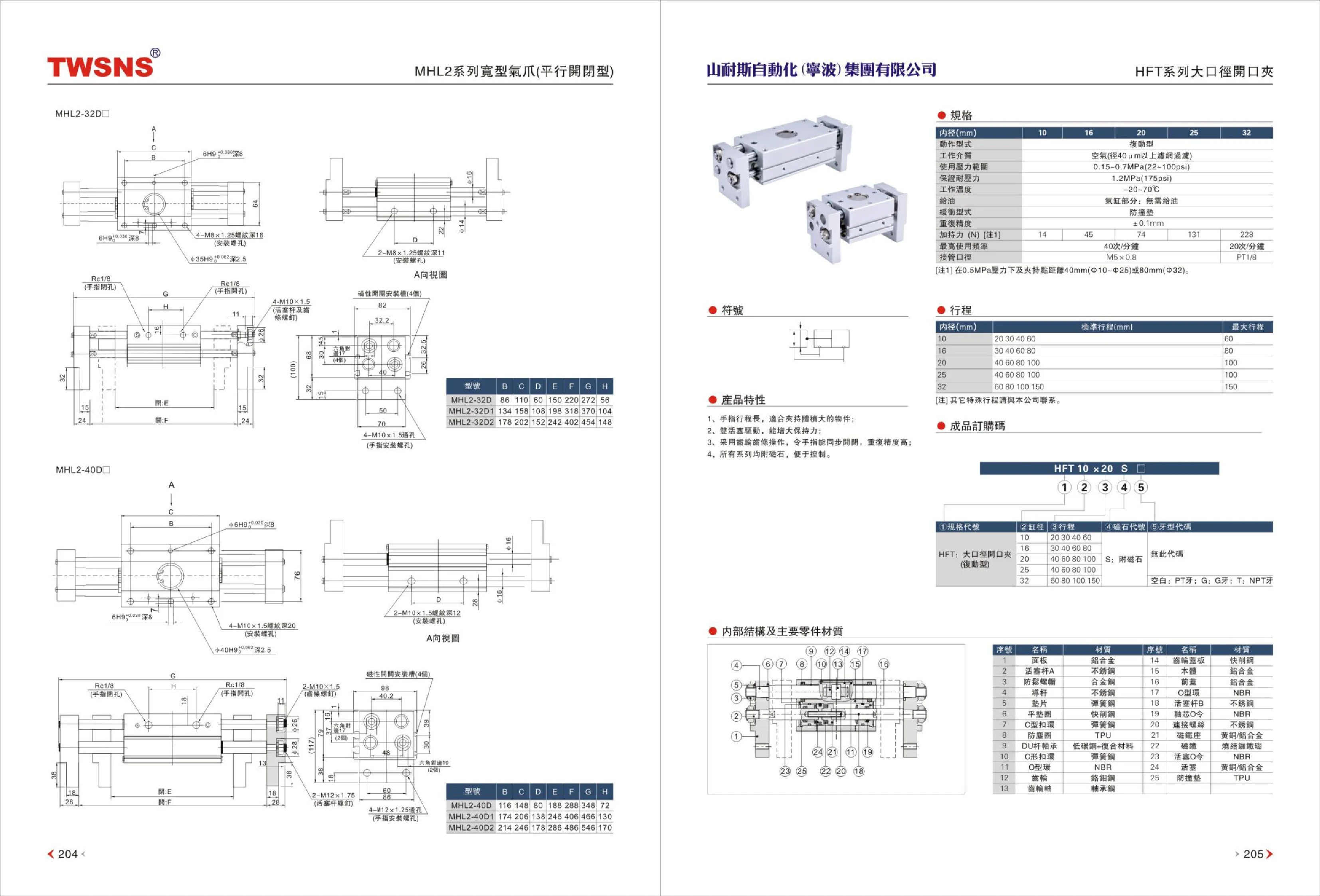
MHL2 Series Parallel Pneumatic Grippers
The MHL2 series consists of parallel-opening pneumatic grippers with dual-piston actuation and a rack-and-pinion mechanism. The two fingers open and close in synchronization, providing high repeat positioning accuracy and strong holding force. The long finger stroke is suitable for gripping larger workpieces. All models have built-in magnets and can be used with magnetic switches to detect fully open and closed positions. Bore sizes are 10, 16, 20, 25 and 32mm. The operating pressure range is 0.15~0.7MPa (22~100psi), proof pressure is 1.2MPa (175psi), operating temperature is -20~70℃, maximum operating frequency is 40 cycles/minute, and the port thread is M5×0.8. The cylinder requires no lubrication. Gripping force varies with bore size; the 32mm bore model provides approximately 228N. These grippers are suitable for parallel gripping of workpieces in automated assembly, handling, sorting and other applications.

MHL2 Series Valve-Type Pneumatic Gripper (Parallel Opening and Closing)
The MHL2 series is a valve-type pneumatic gripper with two parallel jaws and double-acting operation. Its two fingers open and close synchronously along parallel straight paths to grip, hold, position, and transfer small workpieces. Bore sizes include Φ10, Φ16, Φ20, and Φ40, with two fingers on all models. Each bore size has a corresponding finger stroke, allowing selection based on workpiece size and required opening. Gripping force increases with bore size. Select the bore based on workpiece weight, center of gravity, and required gripping force, and select the opening and closing stroke based on the workpiece shape. The compact body can be operated through direct pneumatic connections and supports side and end mounting. It can be integrated with robotic arms, indexing tables, and conveyor lines in applications such as automated assembly, electronic component assembly, and semiconductor and automotive parts handling.

MHL2 Series Valve-Type Pneumatic Gripper (Parallel Opening and Closing)
The MHL2 series valve-type pneumatic gripper features a parallel-opening-and-closing design and is suitable for gripping and handling tasks on automated production lines. Its compact cylinder design is easy to install and offers high precision and reliability. The model code includes parameters such as the series, bore size, type, number, and switch, allowing configuration to meet specific needs. The bore size is 16 mm; type D indicates double acting; the number is 1; and the switch model is Y59A. It is widely used in the electronics, automotive, food, and other industries.
MHS2 Series Angular Pneumatic Gripper
The MHS2 series is an angular pneumatic gripper with a pivoting jaw mechanism. The catalog specifies a 180° opening and closing angle, making it suitable for gripping, turning and transferring small workpieces. The catalog example model MHS2-16-D-2-M9NL comprises the series code, a bore of 16, type D, 2 auto switches and the M9NL auto switch model. It can be used in automated gripping applications requiring position detection. When selecting a model, confirm parameters including bore size, opening and closing angle, operating pressure, port size, and the number and model of auto switches.
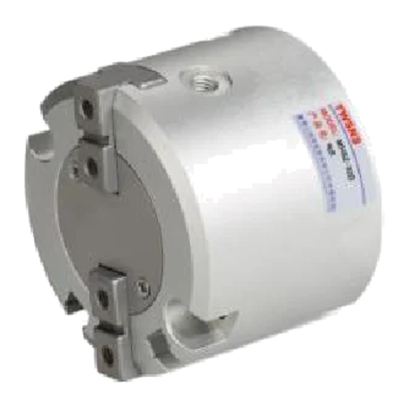
MHS2 Series Parallel Opening and Closing Air Gripper (Cylindrical Body)
The MHS2 series is a parallel opening and closing pneumatic gripper with a cylindrical body, suitable for external and internal gripping. It is available in seven bore sizes: 16, 20, 25, 32, 40, 50, and 63 mm. The operating medium is air; operating pressure is 0.2~0.6 MPa for 16~25 mm bores and 0.1~0.6 MPa for 32~63 mm bores. At 0.5 MPa, external gripping force is 21~502 N and internal gripping force is 23~537 N. Manual stroke is 4~16 mm; maximum operating frequency is 120 cycles/min for smaller bores or 60 cycles/min for larger bores. Port thread is M3×0.5 or M5×0.8. M9P(V), M9N(V), and M9B(V) magnetic switches are available, with lead lengths of 0.5 m (no symbol) or 3 m (L). Gripping point distance: L=20 mm for Φ16~Φ25 and L=30 mm for Φ32~Φ63.

MHS3 Series Parallel Grippers
The MHS3 series three-jaw parallel gripper uses a double-piston mechanism to open and close its three jaws simultaneously, providing self-centering gripping of cylindrical, square, and other workpieces. Standard bore sizes are 16, 20, 25, 32, 40, 50, 63, 80, and 100mm. The gripper has a cylindrical body with M3×0.5 threaded holes and φ4.5 through-holes with flat-bottom counterbores on the mounting surface, allowing front or side mounting. Magnetic switches, such as the M9N, can be fitted to detect the open and closed positions. Powered by compressed air, the gripper is suitable for handling workpieces in automated assembly, material handling, sorting, and other applications.

MHT2 Series Toggle-Type Pneumatic Grippers
The MHT2 series consists of toggle-type (pivoting) pneumatic grippers driven by a double-acting cylinder. Their force-multiplying toggle linkage provides high gripping force for handling heavy workpieces. The self-locking toggle mechanism maintains the grip even if air pressure is suddenly lost or the air supply is cut off, preventing the workpiece from falling. A built-in magnetic ring allows magnetic switches to be mounted directly to detect the open and closed positions of the fingers. Four bore sizes are available: φ32/φ40/φ50/φ63. The operating pressure range is 0.1~0.6MPa, and the ambient and fluid temperature range is 5~60℃. Lubrication is not required; if lubrication is used, use turbine oil No. 1 ISO VG32. The finger opening angle is -3°~28°, holding force at 0.5MPa is 12.4~106 N·m, and weight is 0.80~2.08kg. The model number combines the base model, including bore size, with the number and model of magnetic switches.
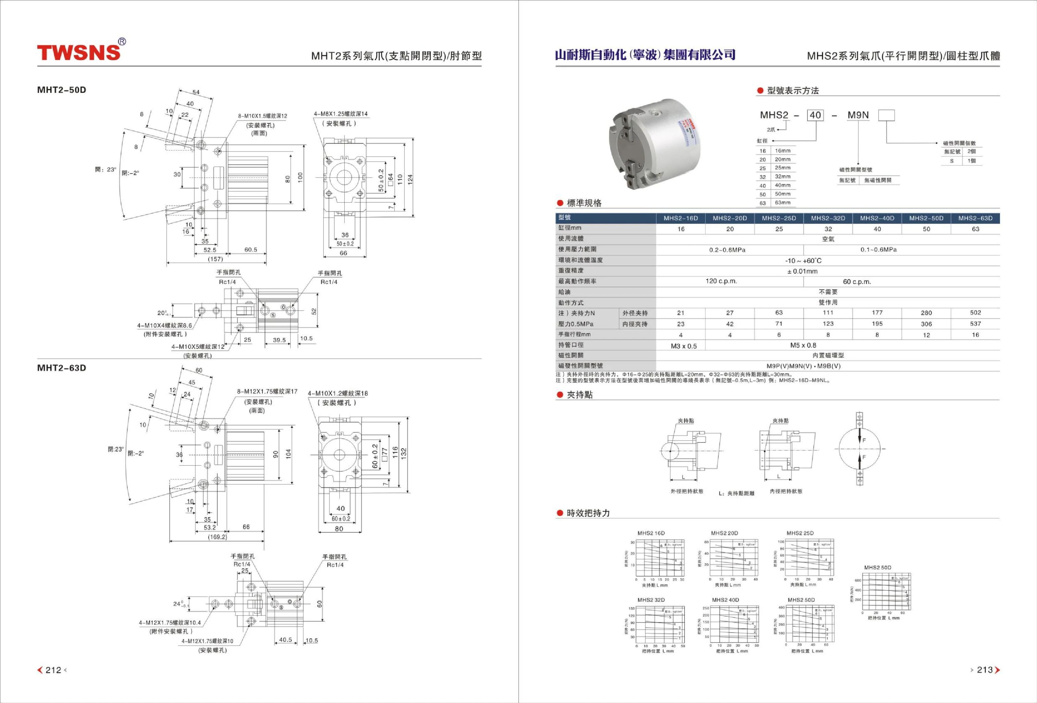
MHT2 Series Pneumatic Grippers (Angular/Toggle Type)
The MHT2 series consists of angular pneumatic grippers that use a toggle mechanism to grip workpieces. They are suitable for picking, gripping, and transferring workpieces in automated equipment. The catalog lists two models, MHT2-50D and MHT2-63D, with the suffix D identifying the basic version of the series. These grippers are often used with accessories such as magnetic switches to detect gripping status. Refer to the full catalog for specific gripping force, stroke, operating pressure, and port size specifications.
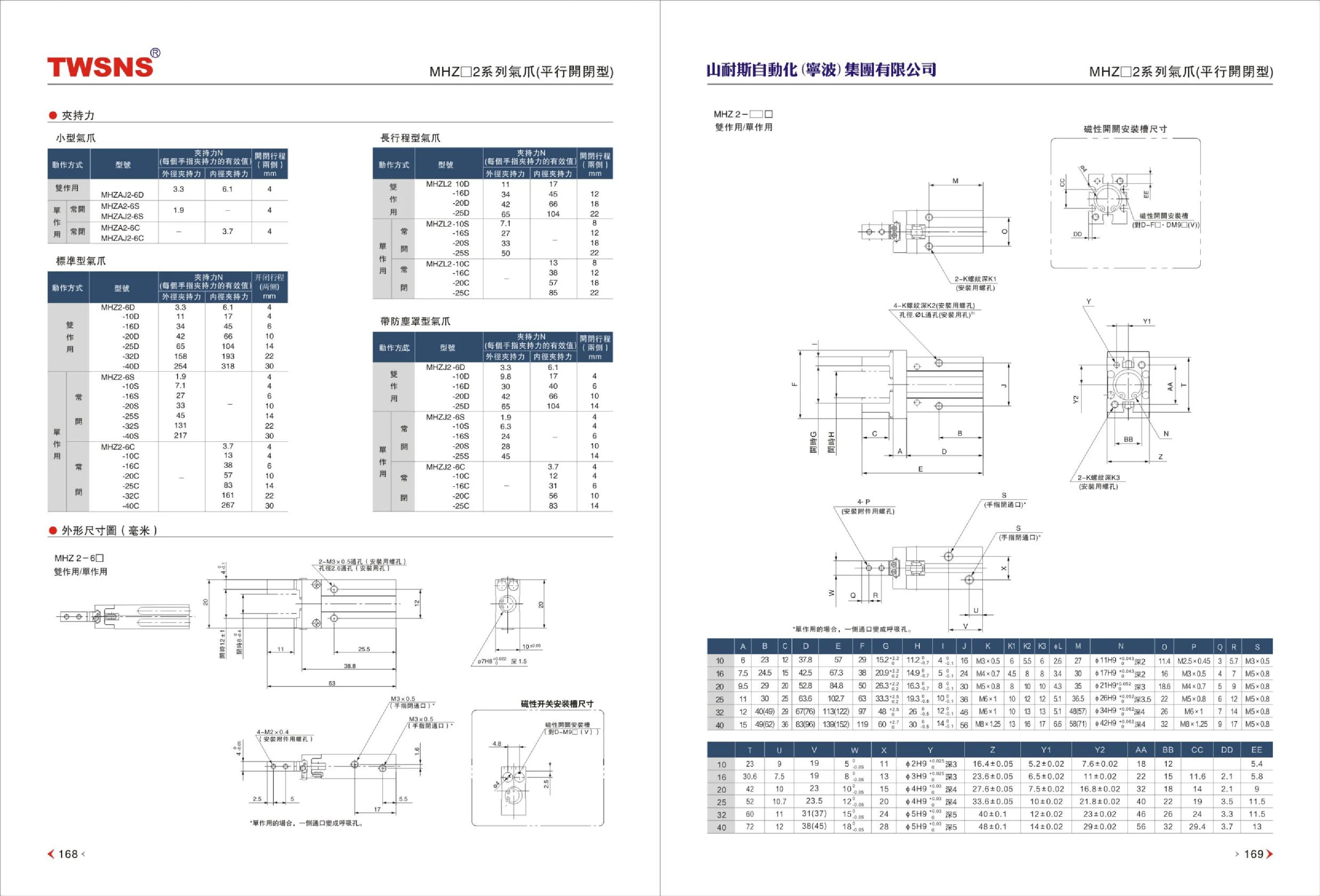
MHZ2 Series Miniature Air Grippers
The MHZ2 series consists of compact pneumatic grippers for gripping, positioning, and handling small workpieces. The series offers double-acting and single-acting configurations. The catalog lists models including MHZAJ2-6D, MHZAJ2-6S, and MHZAJ2-6C, with an effective gripping force of approximately 3.3 N per finger and an opening and closing stroke of approximately 6.1 mm. Reference values for external and internal gripping forces are also provided. The body dimension table covers sizes 10, 16, 20, 25, 32, and 40, showing mounting holes, magnetic switch mounting slots, and major overall dimensions to simplify selection and installation. On single-acting models, the port on one side must serve as a breather port. These grippers are suitable for precision gripping of light loads in electronics, semiconductor, medical, and automated assembly applications.

MHZ2 Series Air Grippers
The MHZ2 series consists of parallel-opening air grippers (pneumatic fingers) with synchronized parallel movement for gripping, holding, positioning, and handling workpieces. Magnetic switches can be fitted for position detection. The series includes the standard MHZ2, compact MHZA2, compact MHZJ2 with dust cover, and long-stroke MHZL2, with bore sizes of Φ6, Φ10, Φ15, Φ20, and Φ25 mm. Actuation options are double-acting D, single-acting normally open S, and single-acting normally closed C. Finger options include basic, side threaded-hole mounting, through-hole mounting in the opening/closing direction, flat fingers, and axial piping (single-acting). Gripper body options include end block with side piping E, end block with Φ4 quick-connect fitting W, end block with axial M5 port M, and end block with axial port and Φ4 hose fitting H. A two-position cam-operated version with 180° opening and closing is also available in bore sizes of 10/16/20/25 mm, for gripping thin workpieces or workpieces requiring a large opening angle.

MV322 Series Mechanical Valves
The MV322 series mechanical valves are 5-port, 2-position (5/2-way) directional control valves. Mechanical actuators, such as rollers, knobs and push buttons, move the spool directly to change the flow direction without a solenoid pilot. The port size is G1/4". A wide range of actuator styles is available, including basic, roller, selector knob, locking push button, flat push button, raised push button and large round push button types, to suit different operating requirements. These valves are designed for manual or mechanical switching of pneumatic circuits in automated equipment and pneumatic control systems. They feature a compact design, reliable response and low actuation force.
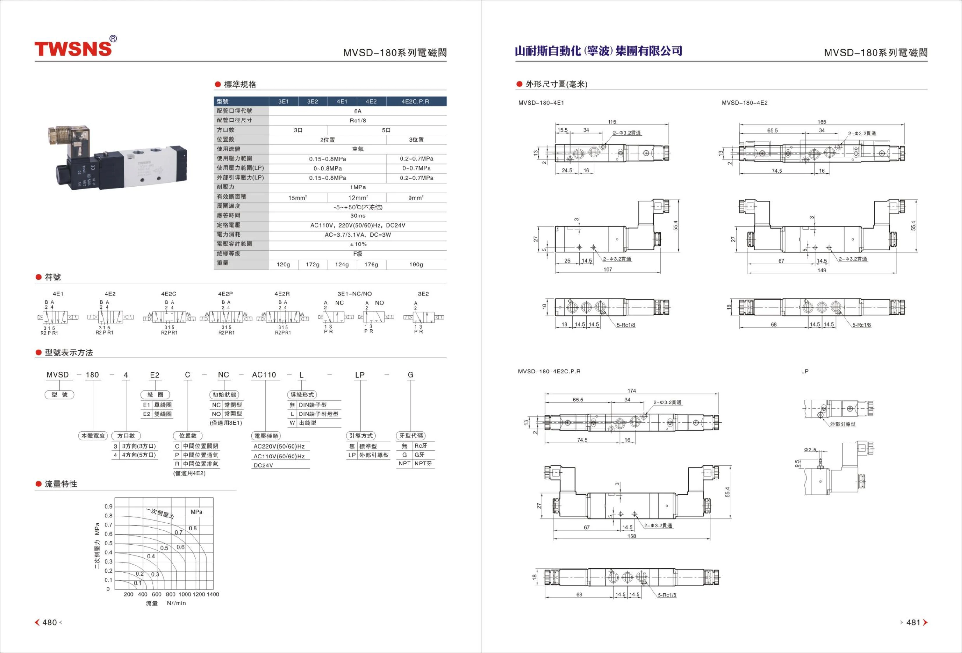
MVS-180 Series Solenoid Valves
The MVS-180 series comprises compact pneumatic directional control solenoid valves, available in 3-port and 5-port configurations with 2 or 3 positions. Designed for air, they have an operating pressure range of 0.15–0.8 MPa (0–0.7 MPa for the low-pressure type, with an external pilot pressure of 0.15–0.8 MPa), a proof pressure of 1 MPa, an effective flow area of approximately 9–15 mm², and a response time of approximately 30 ms. Coil options include AC110V/220V 50/60Hz and DC24V, with power consumption of AC 3.7/3.1VA or DC 3W, a voltage tolerance of ±10%, and insulation class F. The ambient temperature range is -5~+50℃ (no freezing); the 5-port type has an Rc1/8 pipe connection, and each valve weighs approximately 120–190 g.

MVSC-220 Series Solenoid Valves
The MVSC-220 series solenoid valves are pneumatic directional control valves for use with air. The catalog lists models 3E1, 3E2, 4E1, 4E2, and 4E2C.P.R. Piping size codes include 8A, with 6A/8A available for some models. Port sizes include Rc1/4 and Rc1/8, Rc1/4. The series includes 3-port and 5-port configurations with 2 or 3 positions. These valves can be used for flow direction and on/off control in pneumatic circuits of automated equipment. When selecting a model, confirm the port size, number of ports and positions, coil voltage, and mounting method.
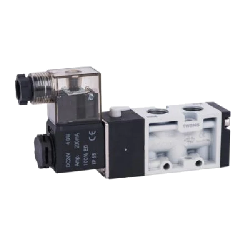
MVSC-260 Series Solenoid Valves
The MVSC-260 series comprises 5-port, 2-position and 3-position pneumatic solenoid valves for directional control of air. The piping size code is 8A, with an RC1/4 port size. The operating pressure range is 0.2–0.8 MPa (0.3–0.8 MPa for 3-position models), with a proof pressure of 1 MPa. The effective area is 18 mm² (16 mm² for 3-position models), response time is approximately 40 ms, and ambient temperature range is -5~+50℃ (non-freezing). Coil voltages include AC110V and AC220V at 50/60Hz, and DC24V, with a voltage tolerance of ±10% and Class F insulation. The series includes the 4E1 and 4E2 2-position models and the 4E2C.P.R 3-position model, weighing approximately 226 g, 314 g, and 444 g, respectively. They are suitable for directional control of pneumatic circuits in automated equipment.

MVSC-300 Series Solenoid Valves
The MVSC-300 series comprises solenoid valves (directional control valves) for air, including 3-port, 2-position models (3E1, 3E2, 3E1-NC/NO), 5-port, 2-position models (4E1, 4E2), and 5-port, 3-position models (4E2C closed center, 4E2P pressure center, 4E2R exhaust center). The operating fluid is air, with an operating pressure range of 0.2~0.8MPa (0.3~0.8MPa for 5-port valves), an effective area of 25~35mm², a response time of 50ms, and an ambient temperature range of -5~+50℃ (no freezing). Rated voltages are AC110V, AC220V (50/60Hz), and DC24V. Power consumption is AC=4.4VA, DC=5W, with a voltage tolerance of ±10% and insulation class F. The port size code is 10A, and the port size is Rc3/8. The explosion-proof version conforms to Eex m II T4. Weight ranges from 293g~565g, depending on the valve type.
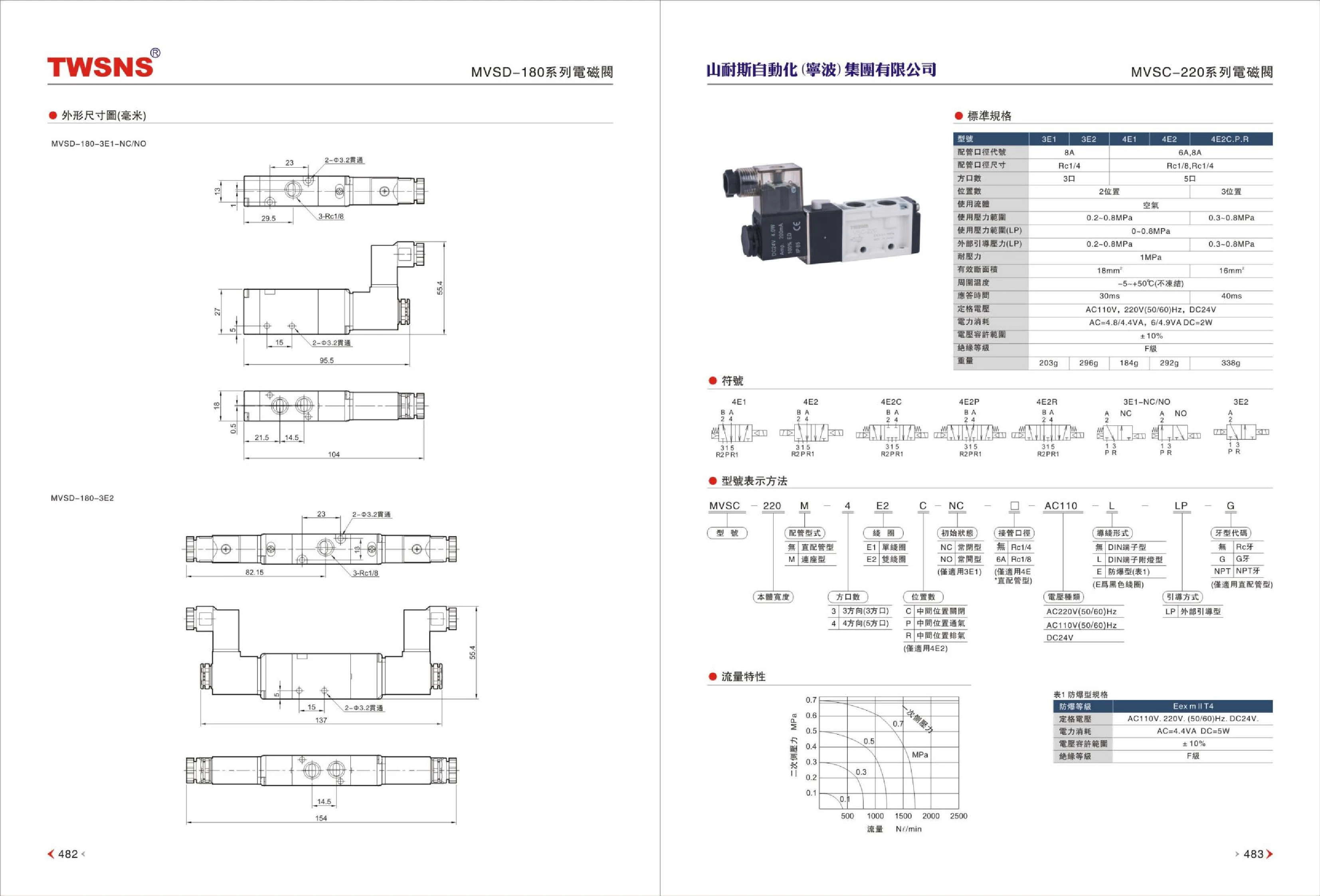
MVSD-180 Series Solenoid Valves
The MVSD-180 series comprises pneumatic solenoid valves. The catalog provides dimensional drawings for two valve types: MVSD-180-3E1-NC/NC and MVSD-180-3E2. The valve body has three Rc1/8 ports, as shown, and two Φ3.2 mm through mounting holes. The drawings also indicate overall dimensions such as 95.5 and 105.4 mm. These valves are suitable for on/off control of pneumatic circuits in automated equipment. When selecting a valve, confirm the model code and functional configuration, such as normally closed or normally open. Consult the complete catalog to verify the coil voltage, operating pressure, and other parameters.
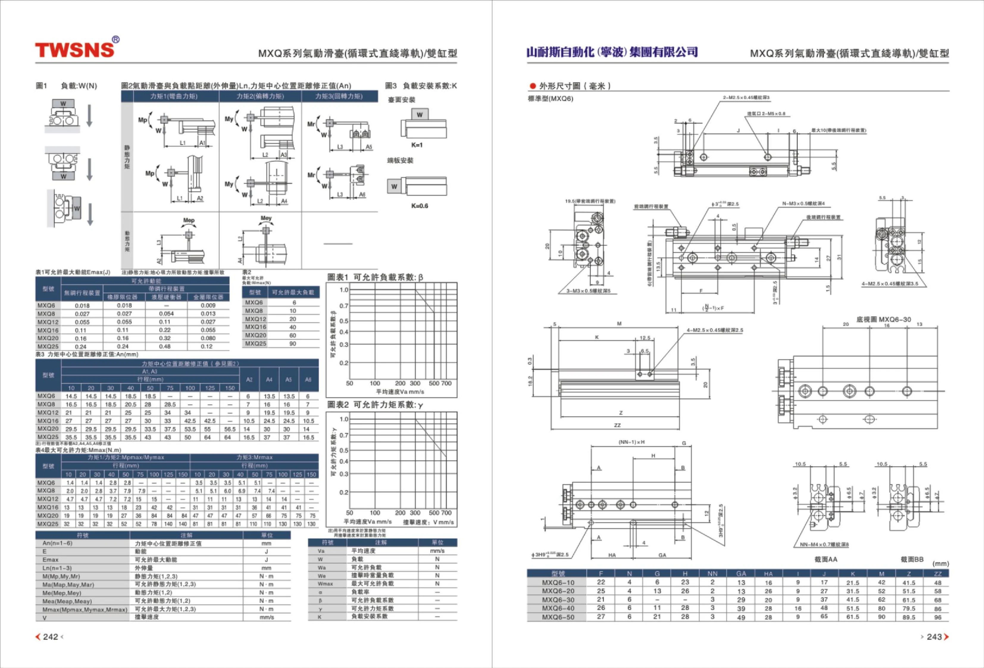
MXQ6 Series Pneumatic Slide Table
The MXQ6 series pneumatic slide table, also known as a pneumatic slide sleeve, is a compact, short-stroke pneumatic actuator commonly used in automated equipment for linear handling, positioning, pushing, pressing, and transferring small workpieces. The series includes MXQ6-10, MXQ6-20, MXQ6-30, MXQ6-40, and MXQ6-50 models, covering strokes from 10~50 mm. The dimensional table provides key dimensions (mm), including F, N, G, H, NN, GA, HA, I, J, K, M, Z, and ZZ. When selecting a model, check the load W, the distance between the load and the slide table (overhang) L1, the moment center position correction value An, the load mounting coefficient K, the maximum allowable axial distance Ema(J), and the allowable moment coefficient γ to ensure operation within the permitted load and moment limits.

MY1B Series Mechanically Jointed Rodless Cylinder
The MY1B series is a mechanically jointed rodless cylinder with a basic design and no switch rail, suitable for long-stroke linear drive applications where installation space is limited. Available bore sizes are 10, 15, 20, 30, and 40 mm, with stroke lengths selectable by model (300 mm in the example). The model code consists of the series number MY1B, bore, stroke, magnetic switch model, and number of switches. For example, MY1B 20 X 300 M9BW S indicates a 20 mm bore, 300 mm stroke, an M9BW magnetic switch, and S for 1 switch. Magnetic switch configurations include no switch, 2 switches, 1 switch, or n switches. A version without a switch rail is also available.

MY1H Series Mechanically Coupled Rodless Cylinders
MY1H series mechanically coupled rodless cylinders transmit force through a mechanical coupling that rigidly links the piston and slider. Unlike magnetically coupled rodless cylinders, they do not slip and offer greater resistance to offset loads and higher load capacity, making them suitable for long-stroke, high-rigidity linear drives. The model code consists of the series, bore, stroke, magnetic switch model, and number of magnetic switches. For example, MY1H 25 300 M9BW S denotes series MY1H, bore Φ25 mm, stroke 300 mm, and 1 M9BW magnetic switch. Piping configuration (unmarked standard type is the basic piping configuration) and linear guide type (unmarked standard type) can also be selected as needed. The cylinder body is typically made of aluminum alloy extrusion, with an integrated guide and dust seals for long-term reciprocating operation in general industrial environments. Cushions and magnetic switches can be installed at both ends to detect end-of-stroke positions. These cylinders are commonly used in automated handling, positioning, pushing, and cutting equipment.

MY1M Series Mechanically Coupled Rodless Cylinder (Slide Guide Type)
The MY1M series is a mechanically coupled rodless cylinder with a slide guide, designed for reciprocating linear motion applications requiring a long stroke, space-saving installation, and the ability to withstand some lateral loading. Available bore diameters are 10, 20, 25, 32, 40, 50, and 63 mm. The dimensional table provides installation and overall dimensions, including A, B, C, G, BH, HG, J, K, L, DL, LH, WL, M, MM, MW, and N, for sizes from 16 to 63 mm, facilitating structural design and guide installation. The mechanical coupling transmits thrust through a connection between the piston and slider, with no protruding piston rod, minimizing the space required at the ends. The slide guide improves guide rigidity and load capacity, making it suitable for automated handling, pushing, and positioning operations. The common specifications table on the original page does not provide values for operation type, operating fluid, maximum and minimum operating pressure, ambient temperature, flow rate and speed, stroke tolerance, or guide type. Consult the complete catalog or the manufacturer when selecting a model.
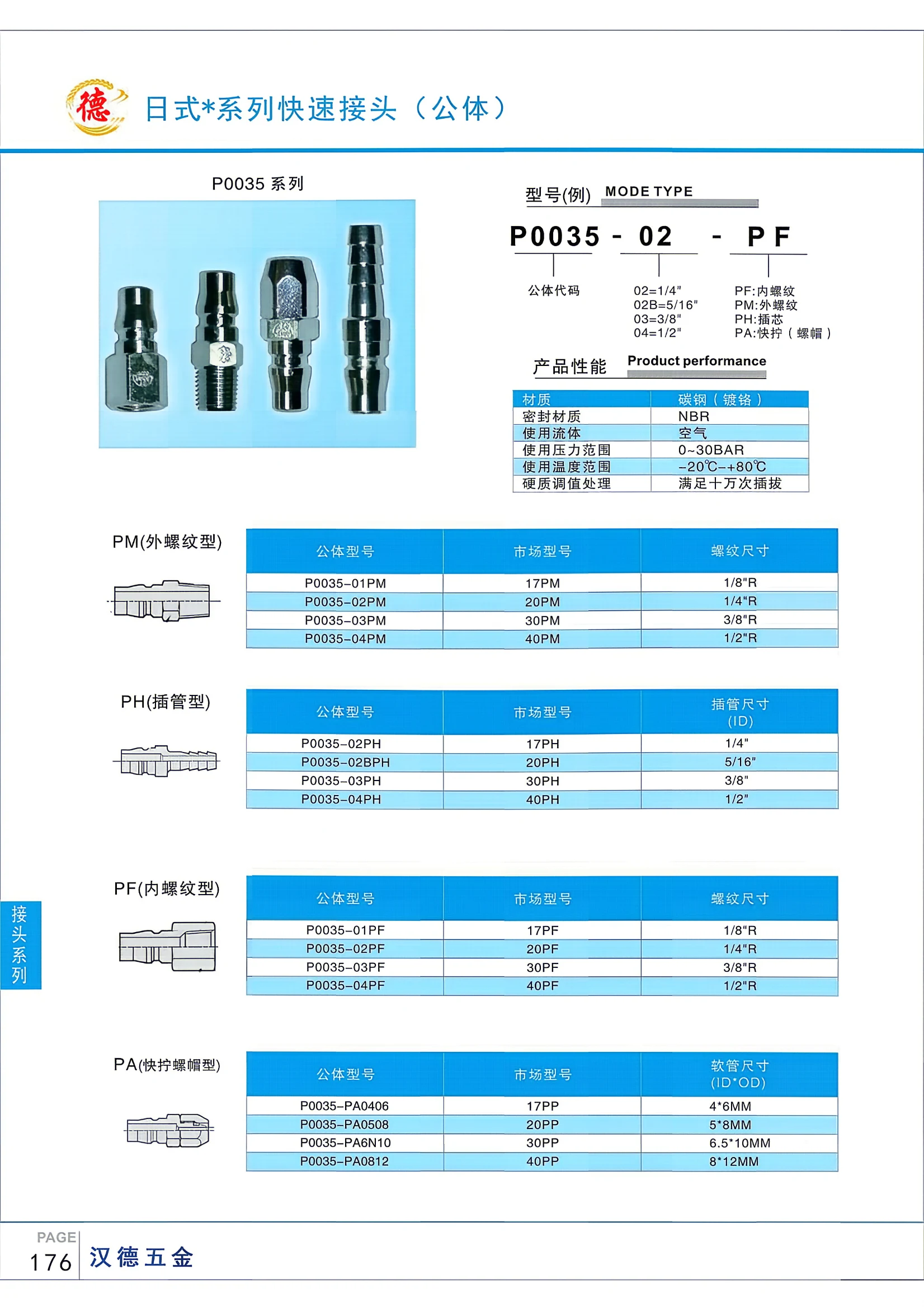
P0035 Series Quick Couplings (Male Body)
P0035 Series Quick Couplings (Male Body) are made of chrome-plated carbon steel and use NBR seals. They are suitable for air and operate at pressures from 0 to 30 bar and temperatures from -20°C to +80°C. Hardened surface treatment ensures up to 100,000 connection and disconnection cycles. Available in several male body codes (02 = 1/4", 02B = 5/16", 03 = 3/8", 04 = 1/2") and fitting types (PF female thread, PM male thread, PH push-in tube, PA quick-tightening nut) to suit different connection requirements.
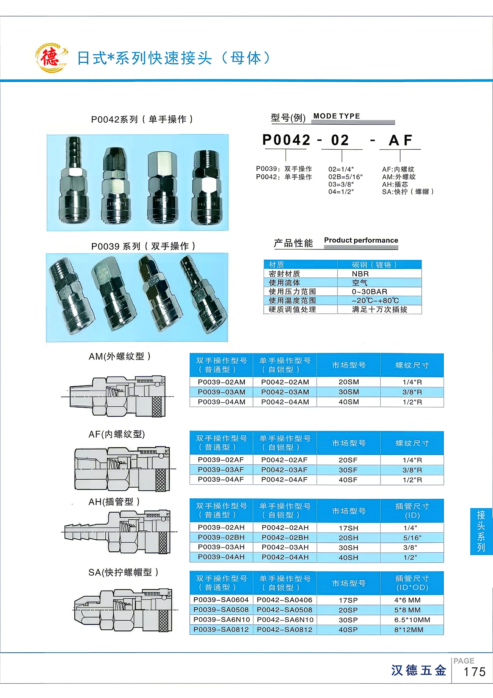
P0042 Series Quick Coupling (Socket)
The P0042 series comprises German/Japanese-style quick-coupling sockets designed for one-handed operation and pneumatic line connections. These models feature male threads and complement the female-threaded P0039 series, which requires two-handed operation. A typical model code is P0042-02-AF; its segments may indicate parameters such as port size and thread type. Widely used in the pneumatic systems of automation equipment, these couplings provide a fast, reliable connection solution.
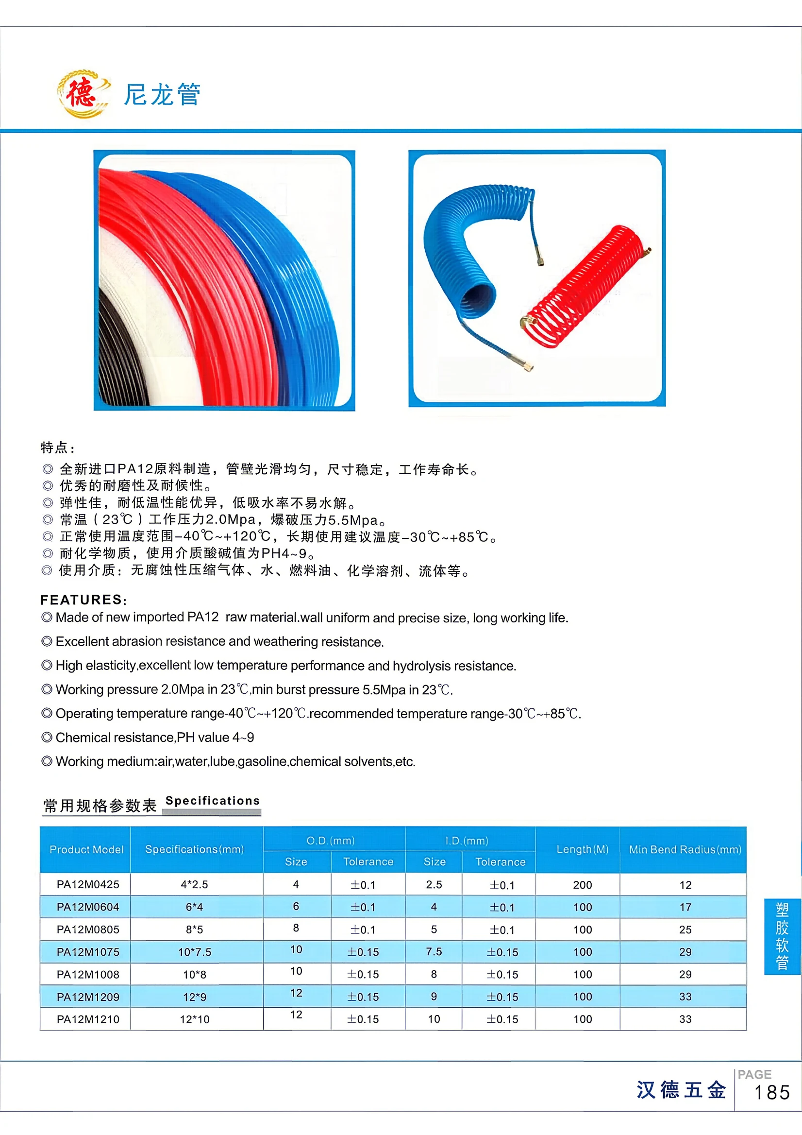
PA12 Series Plastic Tubing
This series of plastic tubing is made from PA12 and manufactured using virgin imported PA12 material. The tubing has a smooth, uniform wall, stable dimensions, and a long service life. It offers excellent abrasion and weather resistance, elasticity, and low-temperature performance. Its low water absorption makes it resistant to hydrolysis. At room temperature (23°C), the working pressure is 2.0 MPa and the burst pressure is 5.5 MPa. The normal operating temperature range is -40°C to +120°C, with a recommended long-term temperature range of -30°C to +85°C. It is resistant to chemicals and suitable for media with a pH of 4–9. Applications include non-corrosive compressed gases, water, fuel oil, chemical solvents, and other fluids. Common sizes range from 4 mm to 12 mm in outer diameter and 2.5 mm to 10 mm in inner diameter, with a variety of options to suit different applications.
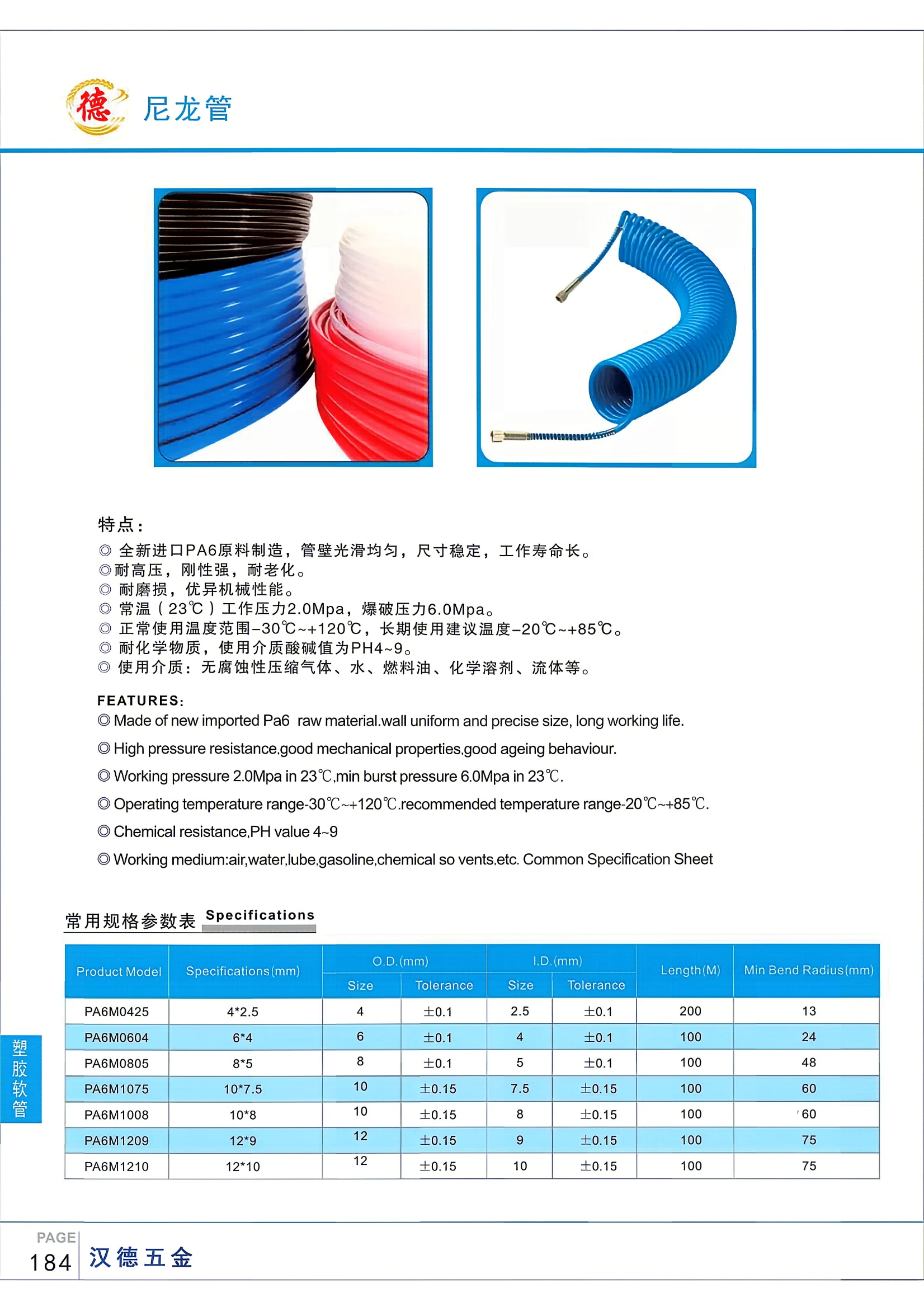
PA6M Series Nylon Tubing
PA6M series nylon tubing is made from brand-new imported PA6 material. It features a smooth, uniform inner wall, stable dimensions, and a long service life. The tubing offers high pressure resistance, rigidity, resistance to aging and wear, and excellent mechanical properties. At room temperature (23°C), the working pressure is 2.0 MPa and the burst pressure is 6.0 MPa. The normal operating temperature range is -30°C to +120°C; for continuous use, the recommended range is -20°C to +85°C. It is resistant to chemicals and suitable for media with a pH of 4–9. Applications include non-corrosive compressed gases, water, fuel oil, chemical solvents, and other fluids. The model code consists of “PA6M” followed by the outer and inner diameters (for example, PA6M0425 denotes an outer diameter of 4 mm and an inner diameter of 2.5 mm). Outer diameters range from 4 to 12 mm, and inner diameters from 2.5 to 10 mm.
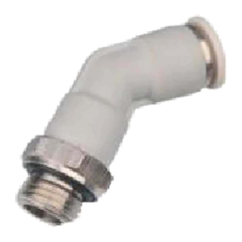
PL45-G Series 45° Male Threaded Fittings
The PL45-G series consists of 45° male threaded pneumatic tube fittings with G threads, designed for installations where tubing must be routed at a 45° angle. They accommodate tube outside diameters of ΦD 4, 6, 8, 10, and 12 mm, with male thread sizes including G1/8, G1/4, G3/8, and G1/2. The catalog specifies overall lengths L1, L2, L3, and L4 and diameters ΦD1 and ΦD2 to help check clearances and select fittings for installation. Model numbers consist of PL45, a tube diameter code, and a G thread size code, such as PL45-04-G01, PL45-06-G04, and PL45-12-G04. These fittings connect pneumatic tubing of the corresponding outside diameter in automated equipment circuits. The material is not specified in the catalog.

PLJ45 Series Push-In 45-Degree Elbow
The PLJ45 series push-in 45-degree elbow (quick-connect pneumatic fitting) connects nylon or polyurethane tubing to pneumatic circuits at a 45° angle. It is commonly used in air supply lines for automation equipment, jigs and fixtures, and pneumatic actuators. The push-in fitting uses an internal retaining clip to secure the inserted tube and an O-ring to provide a self-sealing connection, allowing quick, tool-free installation, removal and reuse. Metric sizes 04/06/08/10/12 correspond to tube outside diameters ΦD 4, 6, 8, 10, 12 mm. Reducing combinations such as 06-04, 08-04, 10-08 and 12-10 are also available for connecting tubes of different diameters. Key dimensions include ΦD tube diameter, ΦD1 outside/hex dimension, ΦD2 connection diameter, and lengths L1~L4 (L1 approximately 12.5~19 mm and L4 approximately 52~80 mm). Select the fitting according to the tube outside diameter and available installation space.
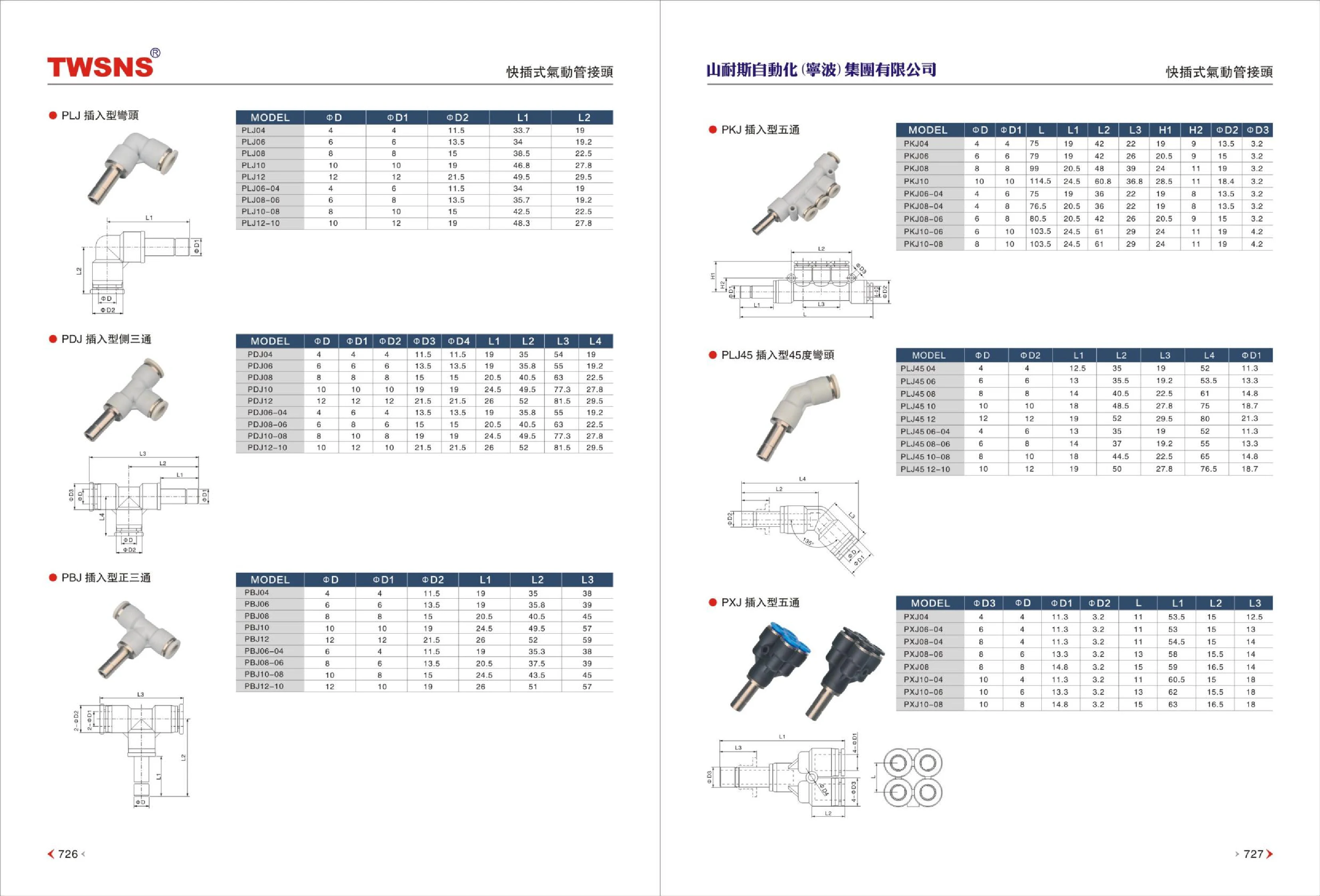
PXJ45 Series Push-In 45° Elbow
The PXJ45 series push-in 45° elbow is a pneumatic push-to-connect fitting for connecting air tubing to actuators or pneumatic systems at a 45° angle. It is suitable for installations with limited routing space that require angled tubing. The push-in connection locks the tube in place when inserted, allowing easy installation and removal without tools. The catalog lists five basic sizes by compatible tube outside diameter: PXJ45 04, 06, 08, 10 and 12. Reducing variants include 06-04, 08-04, 10-08 and 12-10. The table provides diameter dimensions including ΦD (tube outside diameter), ΦD1 and ΦD2, as well as segment lengths L1, L2, L3 and L4, all in mm. These can be used to check the fitting's overall dimensions and installation clearance from adjacent components. Material, working pressure and temperature range are not specified in the source and should be confirmed separately based on air supply conditions and media compatibility.
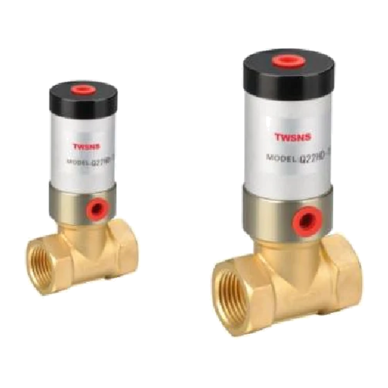
Q22HD Series Pneumatically Controlled Fluid Valves
Q22HD series pneumatically controlled fluid valves feature a pneumatic pilot design, low actuation pressure, responsive opening and closing, and reliable sealing. They can be installed in either inlet or outlet direction. Available in separate, valve-type, single-acting, and double-acting configurations with a choice of seal materials, they are suitable for air, water, oil, liquefied gas, and low-viscosity liquids. Operating pressure is 0.2~0.6 MPa, operating temperature is -5~60℃ (or -5~150℃ for the high-temperature version), nominal diameter is 15~50 mm, flow coefficient is Kv 4~40, and port size is G1/2"~G2". These valves are widely used in equipment for food processing, pharmaceuticals, industrial applications, cleaning, petrochemicals, metallurgy, spraying, and vehicles. They offer a simple design, easy disassembly, low operating costs, and a low failure rate.
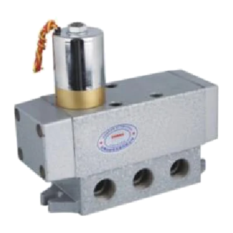
Q24 Series 5/2-Way Spool-Type Directional Control Valve
The Q24 series is a 5/2-way spool-type directional control valve used in pneumatic systems to control the direction and stopping of double-acting cylinders and other actuators. Its spool-type (H) construction features a cylindrical sliding spool, providing a short switching stroke, fast response and long service life. Four control options are available: single solenoid (D), double solenoid (D3), single pneumatic pilot (Q) and double pneumatic pilot (Q2). Port sizes are available in four options: 6 (G1/8", M10×1), 8 (G1/4", M12×1.25), 10 (G3/8", M16×1.5) and 15 (G1/2", M20×1.5), covering low- to medium-flow pneumatic circuits. The valve body can be integrated into pneumatic control circuits without restriction on inlet or outlet orientation. It is suitable for automated pneumatic control of machinery and equipment in food processing, pharmaceuticals, washing, petrochemicals, metallurgy, coating, vehicles and other applications.
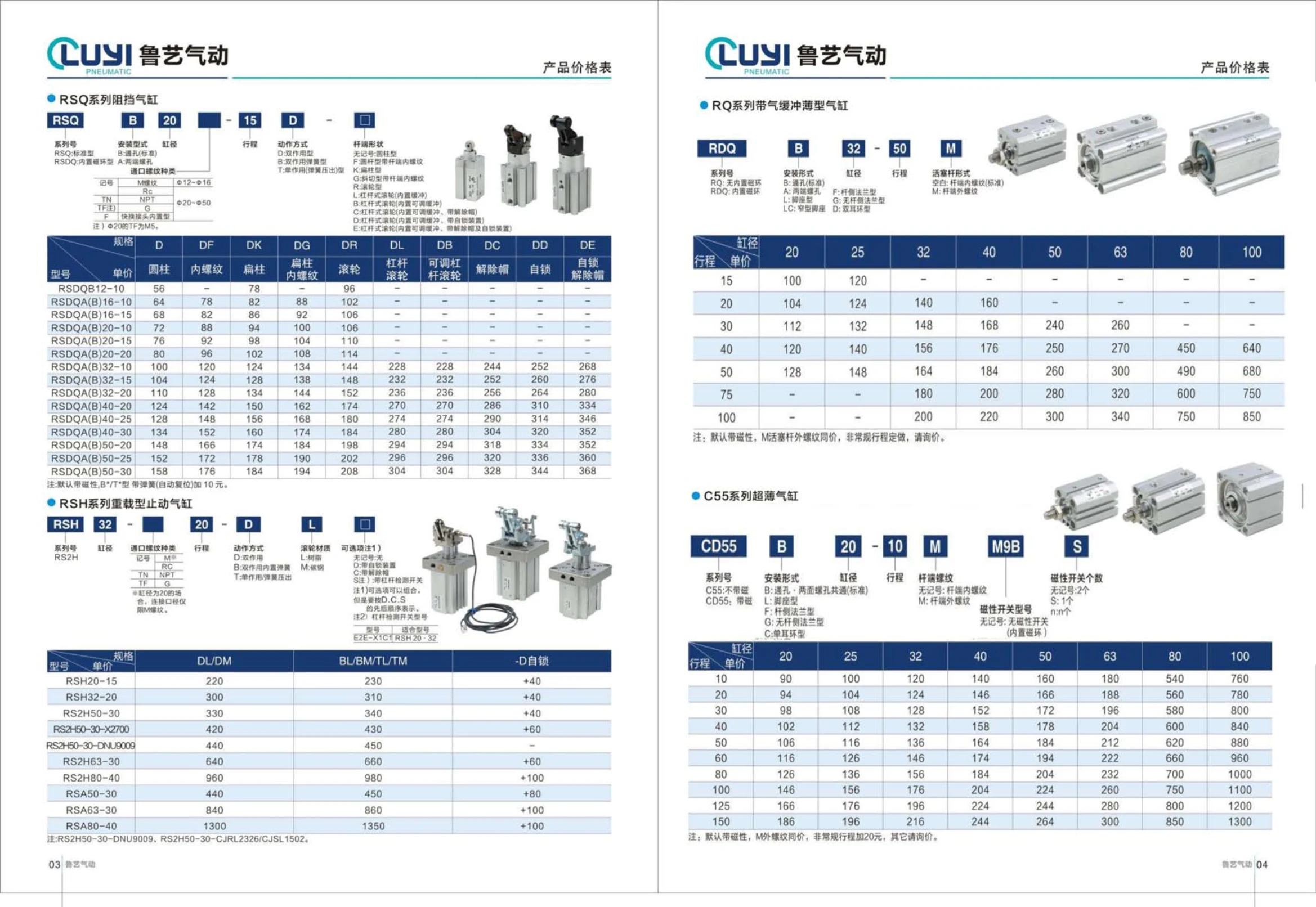
R5Q Series Stopper Cylinders
The R5Q series consists of stopper cylinders for positioning and stopping workpieces on conveyor and assembly lines. The piston rod extends to stop and release pallets or workpieces. The catalog organizes model selection by series number + mounting type + bore + stroke + action type + rod end shape. The series is available in standard R5Q and R5Q built-in magnetic ring versions; the latter has a magnetic ring inside the cylinder and can be fitted with a magnetic switch to provide a position signal. Mounting options are B through-hole (standard) and A internal through magnetic-hole mounting. The bore is 20 mm, and the action type is designated D. The unmarked cylindrical rod end can contact the workpiece directly and allows easy replacement of the cushioning tip. The compact design and simple mounting hole arrangement make the cylinder suitable for stopping small to medium loads in confined spaces. Select the bore and cushioning type according to workpiece weight, conveyor speed, and impact energy, and determine whether magnetic switch detection is required.
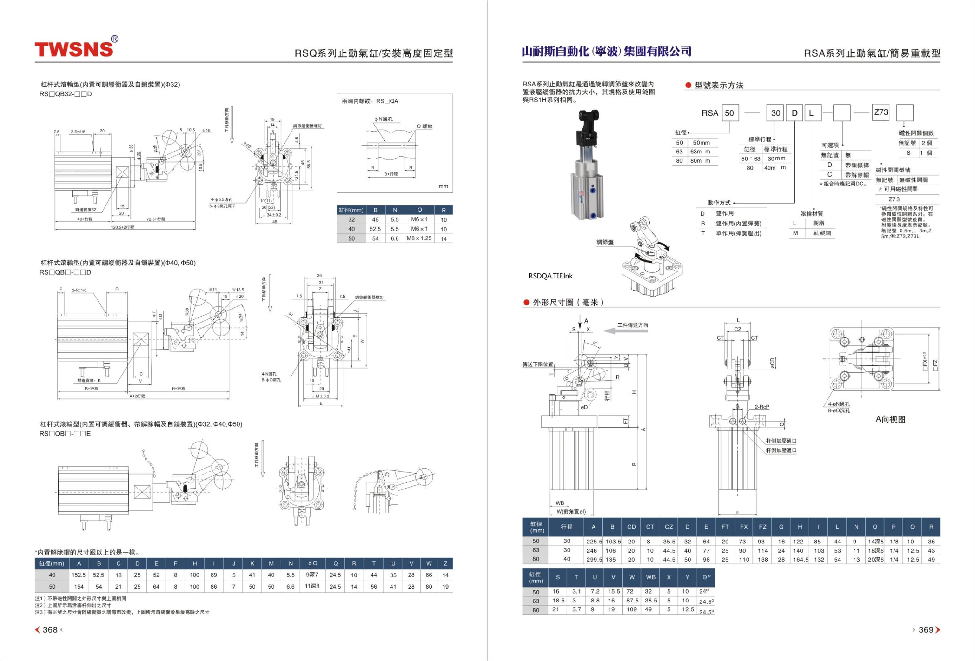
RS1H Series Stopper Cylinders
RS1H series stopper cylinders are pneumatic actuators installed on conveyor lines or at assembly stations to stop and position workpieces precisely at predetermined locations. An integrated roller-type shock absorber absorbs impact and reduces noise and vibration when workpieces arrive at high speed. The related RSA series stopper cylinders use a rotating adjustment dial to vary the resistance of the built-in roller-type shock absorber, accommodating different workpiece weights and conveyor speeds. Their specifications and applications are the same as those of the RS1H series. Products are available in different bore sizes, such as 50. When selecting a model, consider workpiece weight, conveyor speed, stopping position accuracy, and mounting method to determine the required cushioning capacity and stroke.

RS2H Series Roller Lever Stopper Cylinder
The RS2H series consists of roller lever stopper cylinders with bore sizes of 50, 63, and 80 mm, designed to position and stop workpieces on conveyor lines. Air is the working medium, and operating types include double-acting and single-acting (spring-extended). The rod end has a roller lever mechanism with a built-in shock absorber and standard rubber cushioning. The maximum operating pressure is 1.0MPa, and the ambient temperature range starts at approximately -10℃ (with no freezing of air). Stroke length tolerance is +1.4/0. Lubrication is generally not required; if needed, use turbine oil No. 1 ISOVG32. The cylinders are flange-mounted, with Rc1/8 or Rc1/4 port sizes. Model numbers follow the format RS2H[bore]-[stroke][action type], such as RS2H50-30DL and RS2H80-40DM. Magnetic switches such as D-M9BL can be fitted using the built-in magnet. Select the bore size using the conveyed weight and speed together with the friction coefficient charts.

S3 Series Pneumatic Valves
S3 series pneumatic valves are externally controlled, automatic 3-port, 2-position valves for compressed air filtered through a filter rated 40μm or above. Port sizes include 05 (M5), 06 (PT1/8), and 08 (PT1/4), with corresponding effective areas of approximately 2.5, 8.0, and 12.0 mm² (Cv 0.14, 0.45, and 0.67). The operating pressure range is 0~1.0MPa, proof pressure is 1.5MPa, and operating temperature is -20~70℃. The body is made of aluminum alloy and requires no lubrication. G or NPT port threads are available. Models include S3B, S3C, S3D, S3V, S3R, S3L, S3Y, S3PM, S3PF, S3P, S3PL, and S3HS, with suffixes distinguishing the valve types.
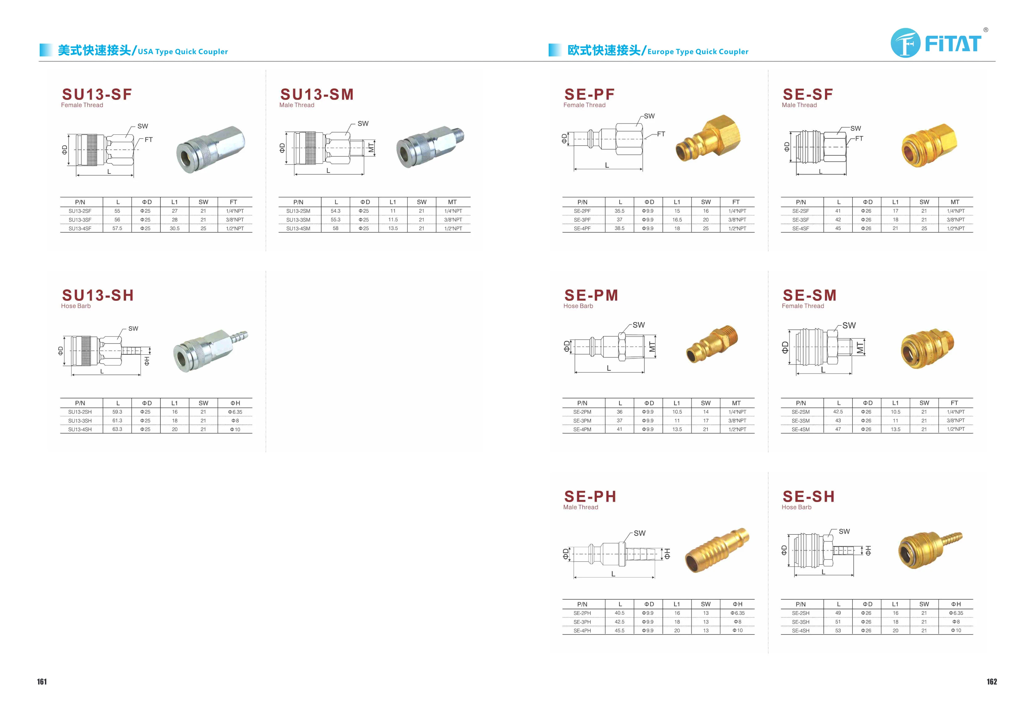
SU13 Series Fittings
The SU13 series comprises fittings for piping connections, all with a body outer diameter of Φ25 and a width across flats SW of 21 mm (25 mm for some 1/2 models). There are three types based on end connection: SU13-SF female thread, SU13-SM male thread, and SU13-SH hose barb. Each type is available in sizes 2, 3, and 4: the threaded types correspond to 1/4 NPT, 3/8 NPT, and 1/2 NPT tapered pipe threads, while the hose barb type accommodates hose outer diameters of Φ6.35, Φ8, and Φ10. Key dimensions include overall length L (approximately 54.3~63.3 mm), body outer diameter ΦD (Φ25), effective end length L1 (11~30.5 mm for threaded types and 16~20 mm for hose barb types), width across flats SW, and thread/hose size. These fittings support straight connections, transition connections, and hose connections in pneumatic and general fluid piping systems.
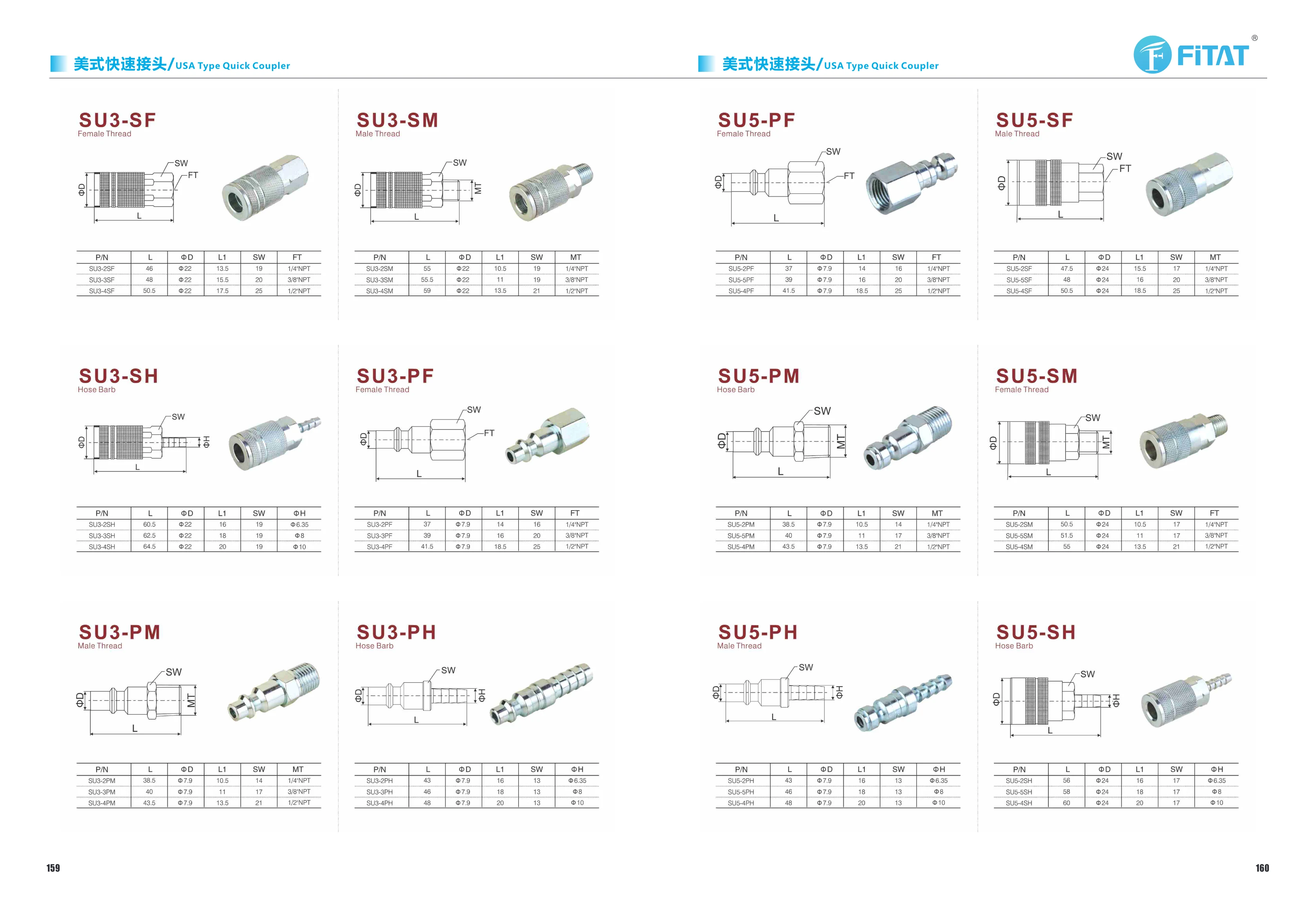
SU5 Series Quick Couplings
SU5 series quick couplings are hose plug connectors for pneumatic and fluid systems, compatible with Φ6.35, Φ8, and Φ10 mm hoses. They have a body diameter of Φ7.9 mm and a hex width across flats of 13 mm. Their overall lengths are 43, 46, and 48 mm, respectively, with corresponding L1 dimensions of 16, 18, and 20 mm. The numbers in the model codes correspond to different hose sizes, while PH denotes the plug/hose fitting end. These products are used in piping systems that require frequent connection and disconnection and can be paired with matching sockets to form quick coupling assemblies. When selecting a model, check the hose size, installation space, and wrench clearance. The table provides dimensions including L, ΦD, L1, SW, and ΦH to facilitate piping layout and interchangeability.
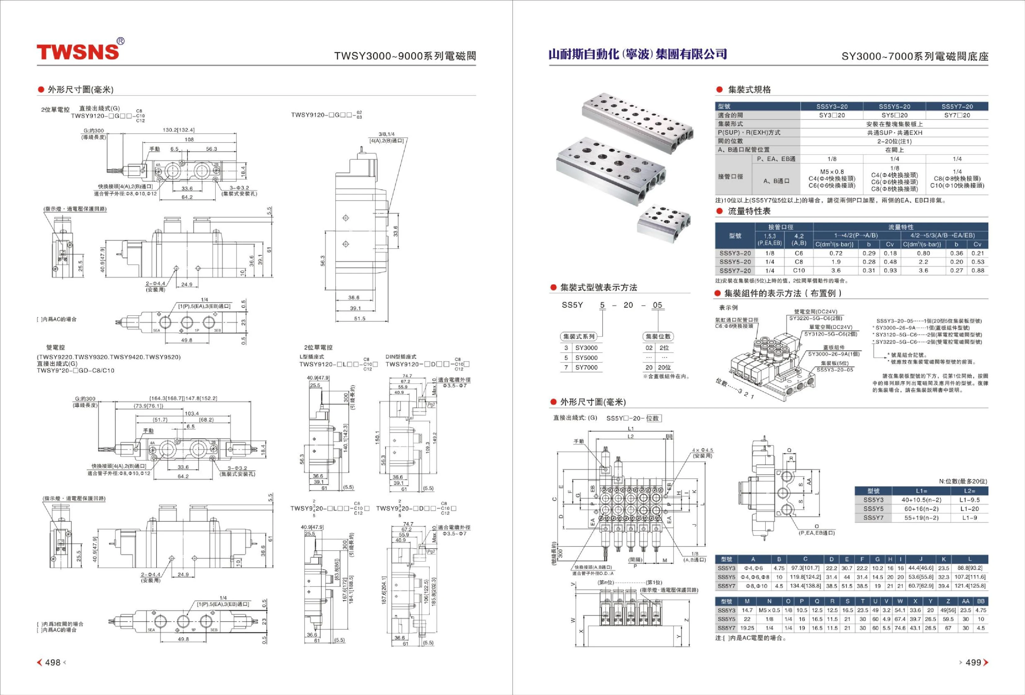
SY3000-7000 Series Solenoid Valve Manifold Bases
The SY3000-7000 series solenoid valve bases use a manifold construction and are compatible with SY3-20, SY5-20, and SY7-20 series solenoid valves, with corresponding base models SS5Y3-20, SS5Y5-20, and SS5Y7-20. The bases are mounted on a single manifold plate, with P(SUP) and R(EXH) arranged for common SUP—common EXH. The manifold supports 2~20 valve stations, and the A and B ports are located on the valve. The P, EA, and EB connection port size is 1/4. These bases are suitable for automated pneumatic control applications requiring centralized air supply and exhaust for multiple valves, reducing piping, saving installation space, and simplifying maintenance.
SY5120 Centralized Wiring Valve Manifold
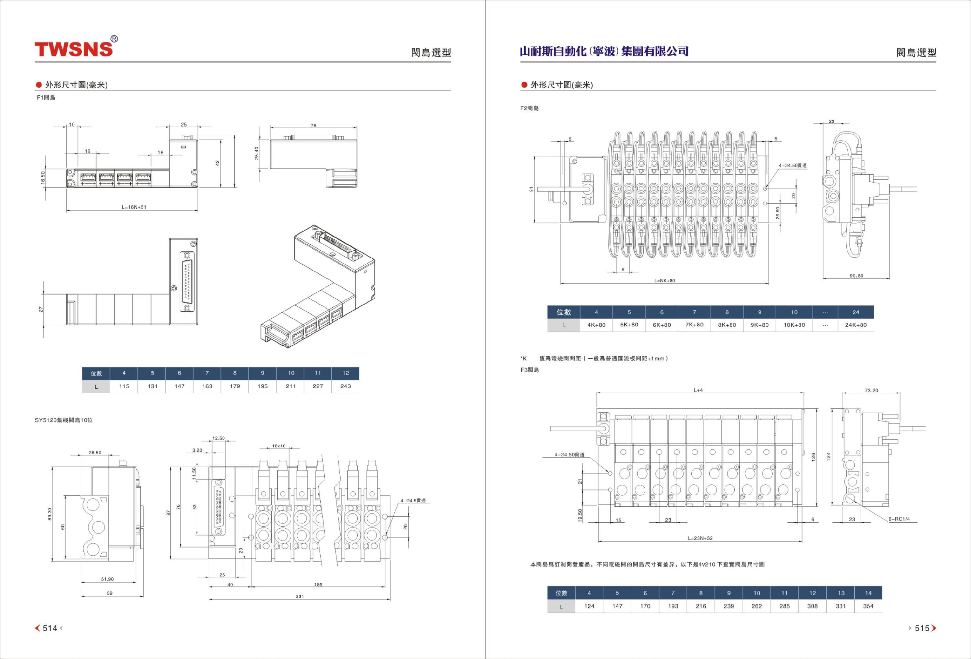
The SY5120 centralized wiring valve manifold (manifold block) provides centralized mounting for SY series, 4V210, and other solenoid valves, allowing multiple valves to share air supply, exhaust, wiring, and piping. The product is available in configurations based on station count: The F1 is a standard manifold with 4~12 stations and an overall length L of 115~243 mm; L increases by 16 mm for each additional station. The F2 length is calculated as L=station count×K+80, where K is the solenoid valve spacing (typically standard manifold spacing+1 mm); it can accommodate up to 24 stations. The F3 is a custom-developed manifold specifically for 4V210 valves, with 4~14 stations corresponding to L 124~354 mm. Manifold dimensions vary by solenoid valve, so confirm the valve model, station count, and spacing when selecting a product.
TC-01 Tube Cutter
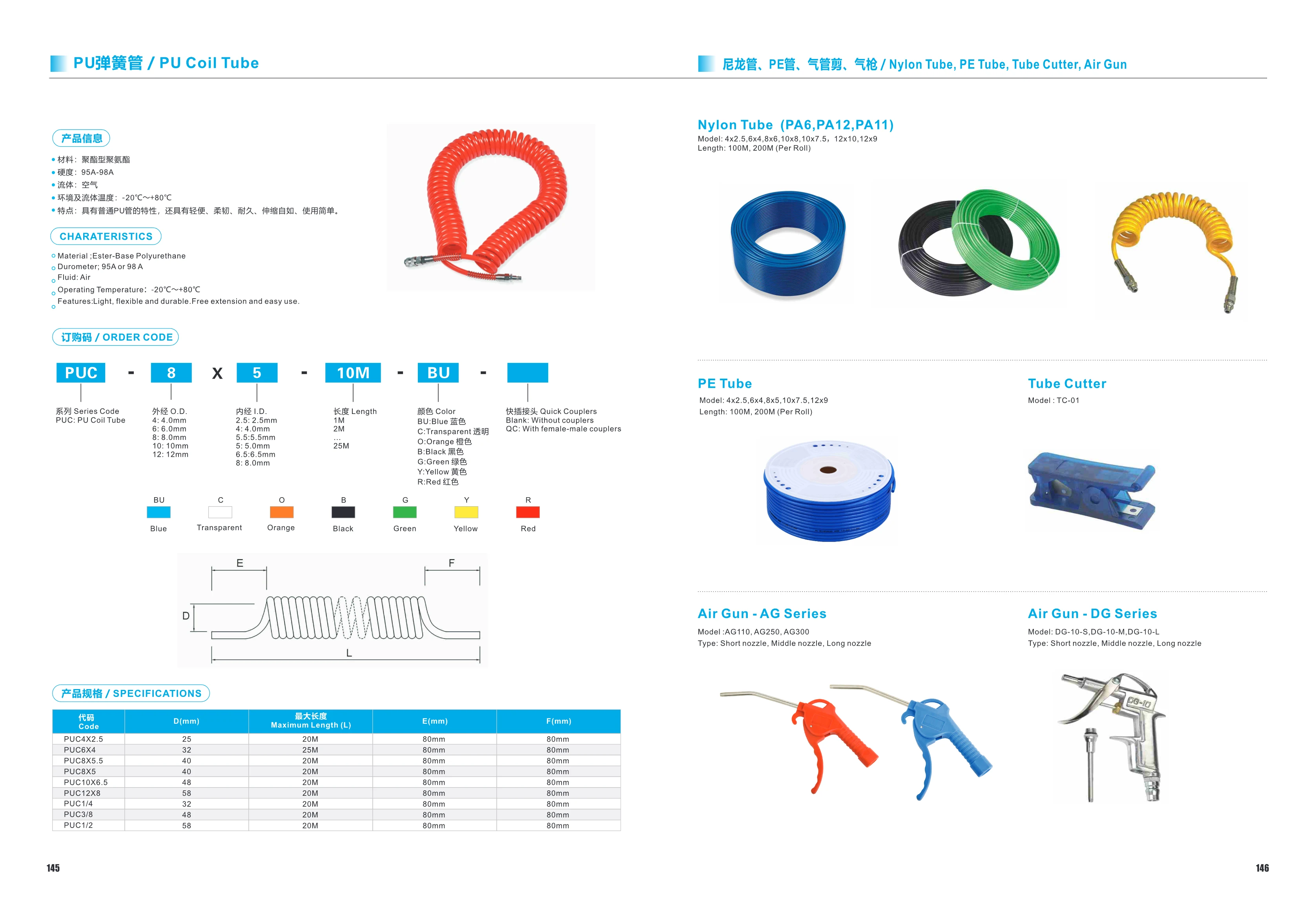
The TC-01 is a handheld cutter for pneumatic tubing, including PU polyurethane tubing and nylon tubing (PA6/PA12/PA11). It produces clean, burr-free cuts without easily flattening the tubing, making it convenient for quick on-site cutting. Lightweight, portable, and easy to use, it is a common tool for pneumatic tubing installation and maintenance. The catalog lists this cutter in a single model, TC-01, for use with nylon tubing in this series (4x2.5, 6x4, 8x6, 10x8, 10x7.5, 12x10, 12x9; 100M/200M per roll).
TSV86 Series Solenoid Valves
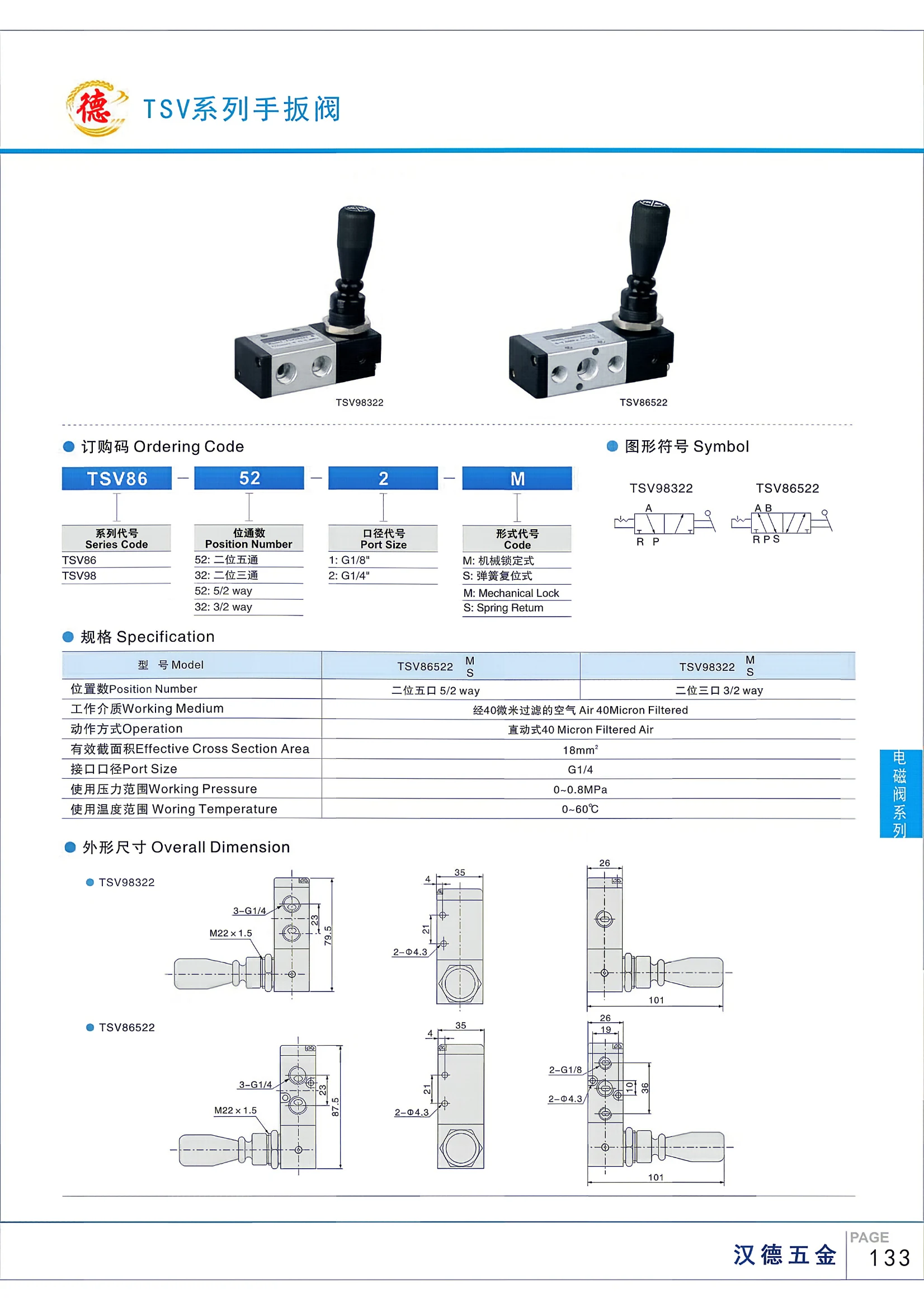
TSV86 series direct-acting solenoid valves use air filtered to 40 microns as the working medium. They have an effective cross-sectional area of 18 mm² and G1/4 ports. The operating pressure range is 0–0.8 MPa, and the operating temperature range is 0–60°C. The series includes two-position, five-way and two-position, three-way valves, available in mechanically latched and spring-return versions. The ordering code consists of the series designation TSV86, the position/way code (52 or 32), the port size code (1 or 2), and the version code (M or S).
TSV98 Series Solenoid Valve
The TSV98 Series Solenoid Valve is a direct-acting pneumatic solenoid valve designed for compressed air filtered to 40 microns. The series primarily offers 2-position, 3-way (3/2-way) models, with G1/8" or G1/4" ports and M (mechanical latching) or S (spring return) configurations. It has an effective cross-sectional area of 18 mm², an operating pressure range of 0–0.8 MPa, and an operating temperature range of 0–60°C. It is widely used in automation control systems.
VEX1133 Series High-Flow Precision Pressure Regulator
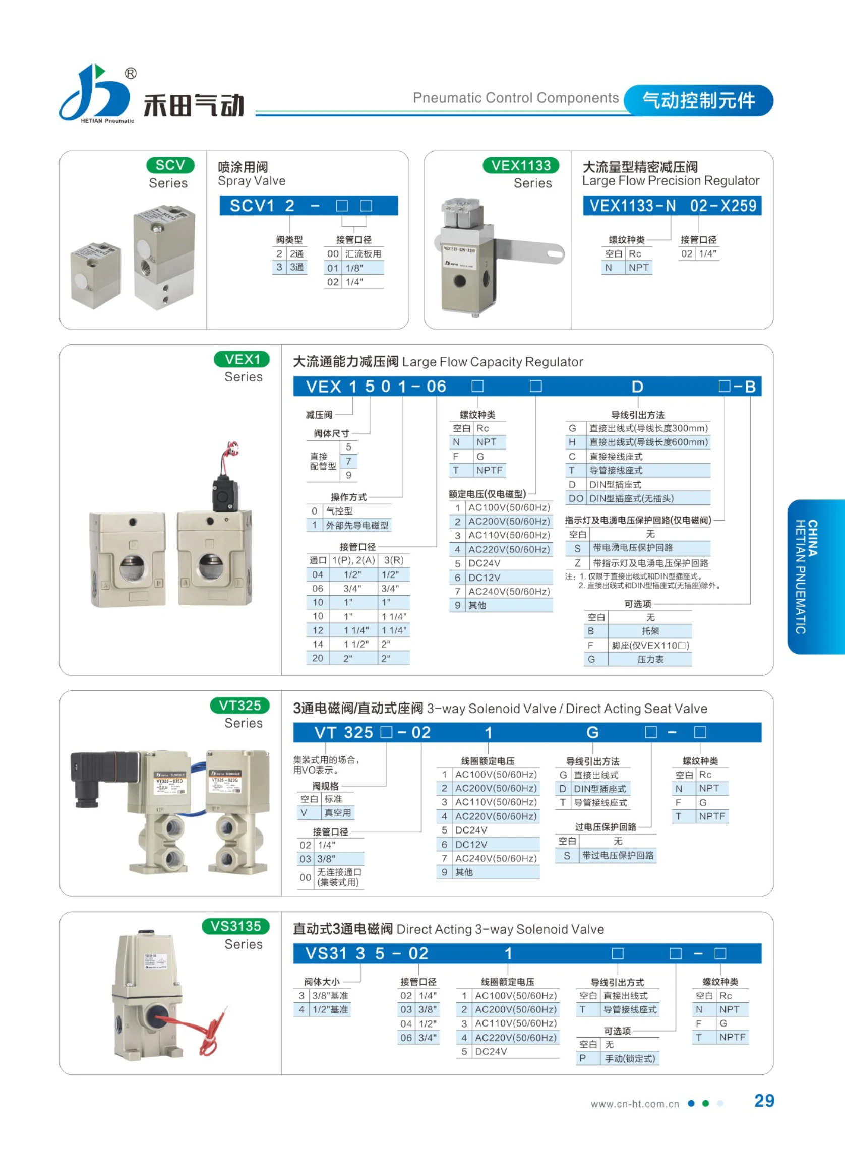
The VEX1133 series high-flow precision pressure regulator is designed for applications requiring a stable, high-flow air supply, such as spray painting and pneumatic control. Its pilot-operated design maintains stable outlet pressure even when inlet pressure fluctuates, providing precise pressure regulation, high flow capacity, and low pressure loss. The valve body has a pressure gauge port and a locking adjustment handwheel to prevent accidental changes to the set pressure. Thread types are Rc (no designation in the model number) and NPT (designated N). The port size is indicated by two digits, with 02 corresponding to 1/4″. A special specification suffix (such as X259) can be added to the end of the model number to meet custom piping connection requirements. When selecting a model, specify the base model VEX1133 + thread type and port size + special specification, in that order.

VF3 Series Solenoid Valve
The VF3 series solenoid valve is a directional control valve for pneumatic circuits. Energizing or de-energizing the coil shifts the valve spool to control the forward, reverse, and stop movements of cylinders and other actuators. The catalog uses a segmented model code: the main model VF3 is followed by codes for the coil and number of positions (130), standard voltage (4), lead type (G for straight lead, D for DIN socket, with C also listed as corresponding to AC110V), manual operation, and threaded port (02 corresponds to PT1/4). Users can select a configuration based on air supply port size, supply voltage, and wiring method. The valve body has PT1/4 ports and is available with either straight leads or a DIN socket for installation in centralized control cabinet or distributed field wiring environments. A manual override allows forced switching during commissioning or power outages. It is suitable for pneumatic control circuits in automated packaging, assembly, and material handling equipment.
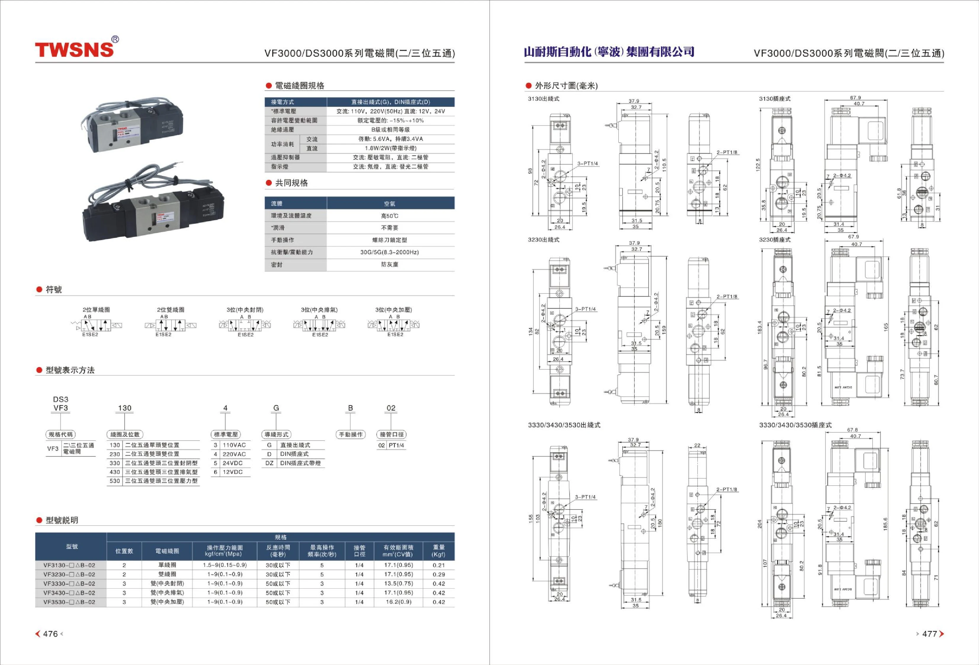
VF3 Series Solenoid Valves
The VF3 series consists of pneumatic directional control solenoid valves with 5-port, 2-position or 3-position bodies for switching the supply and exhaust air paths of pneumatic actuators such as cylinders. Available functions include 2-position single-solenoid, 2-position double-solenoid, and 3-position configurations (closed center, exhaust center, and pressure center). Coils are available with direct lead wires (G) or DIN connectors (D). Standard voltages are 110V/220V AC (50Hz) or 12V/24V DC, with an allowable voltage fluctuation of -15%~+10% and Class B insulation. Power consumption is 5.6VA for AC inrush and 3.4VA for AC holding, or 1.8W/2W for DC (with indicator light). A varistor is used for AC surge suppression and a diode for DC surge suppression. The AC indicator is a neon lamp, and the DC indicator is an LED. The working fluid is air, the maximum ambient and air temperature is 50℃, and no lubrication is required. The manual override is a screwdriver-operated locking type. The valves withstand 30G shock and 5G vibration (8.3~2000Hz) and are sealed against dust. The model code is VF3-[coil and number of positions]-[standard voltage]-[wiring type]-[manual override]-[electrical connection size].

VF5 Series Solenoid Valves
The VF5 series comprises five-port solenoid valves (directional control valves) for pneumatic systems, providing on/off and directional control of air circuits in automated equipment, packaging machinery, assembly lines and other applications. Products are ordered using a segmented specification code beginning with the base model VF5, followed by the coil and position configuration (120), standard voltage (4), lead type (G for direct lead wires, D for a DIN connector; an AC110V specification is also available), and threaded port size (02 corresponds to PT1/4). Single- and double-solenoid configurations are available, with a manual override for commissioning and emergency operation. Electrical connections can be made via direct lead wires or a standard DIN connector for easy maintenance and replacement. The valve mounts through holes in the body or on a manifold, and its PT1/4 threaded ports are compatible with conventional pneumatic tubing and push-in fittings.